EP1297955B1 - Dispositif pour la fixation d'un cliché d'impression - Google Patents
Dispositif pour la fixation d'un cliché d'impression Download PDFInfo
- Publication number
- EP1297955B1 EP1297955B1 EP02020729A EP02020729A EP1297955B1 EP 1297955 B1 EP1297955 B1 EP 1297955B1 EP 02020729 A EP02020729 A EP 02020729A EP 02020729 A EP02020729 A EP 02020729A EP 1297955 B1 EP1297955 B1 EP 1297955B1
- Authority
- EP
- European Patent Office
- Prior art keywords
- clamping
- rail
- printing
- tensioning
- lever
- Prior art date
- Legal status (The legal status is an assumption and is not a legal conclusion. Google has not performed a legal analysis and makes no representation as to the accuracy of the status listed.)
- Expired - Lifetime
Links
Images


Classifications
-
- B—PERFORMING OPERATIONS; TRANSPORTING
- B41—PRINTING; LINING MACHINES; TYPEWRITERS; STAMPS
- B41F—PRINTING MACHINES OR PRESSES
- B41F27/00—Devices for attaching printing elements or formes to supports
- B41F27/12—Devices for attaching printing elements or formes to supports for attaching flexible printing formes
- B41F27/1218—Devices for attaching printing elements or formes to supports for attaching flexible printing formes comprising printing plate tensioning devices
- B41F27/1225—Devices for attaching printing elements or formes to supports for attaching flexible printing formes comprising printing plate tensioning devices moving in the printing plate end substantially rectilinearly
- B41F27/1243—Devices for attaching printing elements or formes to supports for attaching flexible printing formes comprising printing plate tensioning devices moving in the printing plate end substantially rectilinearly by pivotal or swivelling motion, e.g. by means of a rocking lever
Definitions
- the invention relates to a clamping device for a printing form according to the preamble of claim 1.
- the printing for example formed as a thin aluminum plate is first attached to the leading edge on a mounted in a cylinder channel clamping device. After mounting the printing forme around the outer circumference of the forme cylinder, the attachment of the trailing end of the printing forme then takes place in a further clamping rail. By moving the rear clamping rail towards the center of the channel, a tensile force is exerted on the printing form. This tensile force can be exercised in particular by spring elements which press in the direction of the center of the channel in the rear clamping device (the tensioning rail).
- adjusting devices for printing plates have become known, as these are described in particular in DE 196 34 947 C1.
- the sectionally divided rear tensioning rail is assigned in each case one (each section) control element.
- the actuator is manually operable and is brought against a spring force in abutment with the respective clamping rail section.
- the adjusting element By actuating the adjusting element, the tensile force exerted on the printing end of the printing plate can be partially reduced.
- the adjusting elements of the individual clamping rail sections are released due to the spring force, so that an automatic release is given, this device can therefore be used in an automated printing plate changing device.
- a disadvantage of this known device is that the adjusting elements serving adjusting only in the direction of "pull force" act on the individual clamping rail sections. A correction over the printing end of the printing form ago in the direction of "longer printing” is not possible.
- the object of the present invention is therefore to expand a clamping device according to the preamble of the preamble of claim 1 such that a self-releasing plate change and the impressed correction is also present over long periods of time.
- the rear tensioning rail or each individual portion of the divided rear tensioning rail, at least one unilaterally acting blocking is associated, which is releasable by acting on the rear tensioning rail and for changing a pressure plate activatable actuator.
- the locking direction of the locking mechanism is in the direction of "tensile force on pressure plate" increase, i. by a manually operable and attachable to corrections to the clamping device hand tool exerted by the rear clamping rail on the pressure plate pulling force is increased and fixed by the locking mechanism.
- the actuating device assigned to the rear tensioning rail lifts the locking during the engagement on the rear tensioning rail to change the pressure form, so that then the rear tensioning rail has the full mobility required for changing the pressure form.
- the pivotally mounted in the cylinder channel clamping rail, or each section, a pair are associated via each lever arm articulated push rods, which cooperate with a respective terminal as a block.
- the two individual push rods associated terminals are with coupled with the actuating device for pivoting the rear clamping rail cooperating contour, so that the force exerted by the terminals on the clamping rail and thus the pressure force clamping force when changing a printing form can be canceled by loosening the lock.
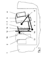
- Figures 1 to 10 show the clamping device according to the invention in different phases of movement.
- a clamping rail 2 is arranged for receiving the front edge of a printing forme, not shown in Figure 1. This extends over the format width of the cylinder 1.
- end of a printing plate is divided over the format width divided into several sections rear tensioning rail 3, 4, which is mounted movably about a total pivot axis 6.
- the tensioning rail 3, 4 consists of an upper part 3 and a lower part 4 for receiving and releasing the pressure plate end.
- the rear tensioning rail 3, 4 is coupled to exert a clamping force on the pressure forming end with spring elements, the rear tensioning rail 3, 4 through this not shown spring elements is pivoted counterclockwise in the middle of the channel.
- a two-armed lever 7, 8 can be actuated by not shown adjusting means. Pivoting the two-armed lever 7, 8 in the clockwise direction causes the correspondingly shaped end of the lever 7 comes into contact with the back of the upper part 3 of the rear clamping rail 3, 4 and the rear Clamping rail 3, 4 is pre-pivoted so against the spring force to the pressure end channel edge of the forme cylinder 1.
- two individual, adjacent push rods 10 are hinged to a lever arm 9. These push rods 10 engage in each case through an opening of a clamping device 12, 12.1, said clamping device 12, 12.1 (see Figure 4) as the push rods 10 arranged side by side and articulated via a respective bolt by a cross-slot 13 on the back of the front clamping device 2 are.
- the clamping devices 12, 12.1 can thus be moved by a predetermined amount in the radial direction of the cylinder 1, furthermore the clamping devices 12, 12.1 are also pivotable.
- a contour 14 is hingedly connected to a lever.
- This contour 14 acts together with the correspondingly shaped end of the lever 8, so that the clamping effected between the clamping device 12, 12.1 and the push rods 10 can be lifted in a clockwise direction during a pivoting movement of the lever 8.
- each compression springs are set.
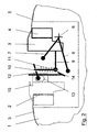
- Figure 2 shows that in the front clamping device 2, the leading end of a printing form 5 was inserted and clamped.
- the trailing end of the printing plate 5 is also between the lower part 4 and upper part 3 of the rear tensioning device attached.
- the clamping rail 3, 4 was pivoted in the direction of pressure end channel wall. This was done by the actuator, not shown, as well as by pivoting the lever arm. 7
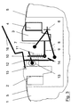
- FIG. 3 shows, like FIG. 2, the printing form 5, which is completely drawn onto the forme cylinder and which is held in the front clamping device 2 and the rear clamping device 3, 4.
- a trained as a lever hand tool is recognized with one end in a recess 15 of the front clamping device on the top of one of the clamping devices 12 acting, so that now on the clamping means 12 and the associated push rod, the force exerted by the lever 16 force in a the clamping force the printing form 5 magnifying pivotal movement of the rear clamping rail 3, 4 can be implemented.
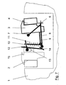
- FIG. 10 shows the printing form 5, which is completely wound onto the forme cylinder 1 and which is fastened at its leading end in the clamping device 2 and its trailing end in the clamping device 3, 4.
- the not shown on spring elements and the rear clamping rail 3, 4 exerted on the printing plate 5 clamping force holds them securely on the outer circumference
- the two-armed lever 7, 8 stands neither with the clamping rail 3, after with the contour 14 in contact, so that the force applied by the spring elements not shown clamping force completely on the rear clamping rail 3, 4th
Landscapes
- Engineering & Computer Science (AREA)
- Mechanical Engineering (AREA)
- Supply, Installation And Extraction Of Printed Sheets Or Plates (AREA)
- Dot-Matrix Printers And Others (AREA)
- Silver Salt Photography Or Processing Solution Therefor (AREA)
- Ink Jet (AREA)
Claims (6)
- Dispositif de fixation pour un cylindre d'impression d'une machine d'impression, notamment pour des éléments de vernissage ou d'impression de machines d'impression offset à feuilles, comprenant un rail de fixation monté mobile dans le canal du cylindre et recevant une extrémité d'une plaque d'impression, la force de fixation exercée sur la plaque d'impression étant produite par des éléments de ressort associés au rail de fixation, et un dispositif d'actionnement déplaçant le rail de fixation à l'encontre de cette force de ressort ainsi qu'un outil pouvant être manipulé à la main, au moyen duquel le rail de fixation peut être déplacé pour augmenter la force exercée sur la plaque d'impression,
caractérisé en ce que
l'on associe au rail de fixation (3, 4) un blocage (10, 12, 12.1) agissant d'un côté dont l'effet de blocage peut être supprimé par le dispositif d'actionnement (7, 8) activé lors du remplacement d'une plaque d'impression. - Dispositif de fixation selon la revendication 1,
caractérisé en ce que
le blocage (10, 12, 12.1) est réalisé sous forme de tige coulissante (10) articulée au rail de fixation (3, 4), qui coopère avec un dispositif de serrage (12) supporté de manière fixée au cylindre. - Dispositif de fixation selon la revendication 2,
caractérisé en ce que
l'on associe au rail de fixation (3, 4) deux tiges coulissantes (10) qui coopèrent avec deux dispositifs de serrage (12, 12.1). - Dispositif de fixation selon l'une quelconque des revendications précédentes,
caractérisé en ce que
l'outil pouvant être manipulé à la main (16) est réalisé sous forme de levier, qui agit par le biais du blocage (12, 12.1) sur le rail de fixation arrière (3, 4). - Dispositif de fixation selon l'une quelconque des revendications précédentes,
caractérisé en ce que
le dispositif d'actionnement (7, 8) est réalisé sous forme de levier à deux bras (7, 8), un levier (7) coopérant avec le rail de fixation (3, 4) et le deuxième levier (8) coopérante de manière à desserrer le dispositif de blocage (12, 12.1). - Dispositif de fixation selon la revendication 5,
caractérisé en ce qu'un
contour (14) est accouplé au dispositif de serrage (12, 12.1), lequel coopère avec l'extrémité du levier (8) du dispositif d'actionnement.
Applications Claiming Priority (2)
| Application Number | Priority Date | Filing Date | Title |
|---|---|---|---|
| DE10151052 | 2001-09-26 | ||
| DE10151052A DE10151052C1 (de) | 2001-09-26 | 2001-09-26 | Spannvorrichtung für eine Druckform |
Publications (2)
| Publication Number | Publication Date |
|---|---|
| EP1297955A1 EP1297955A1 (fr) | 2003-04-02 |
| EP1297955B1 true EP1297955B1 (fr) | 2006-07-26 |
Family
ID=7702681
Family Applications (1)
| Application Number | Title | Priority Date | Filing Date |
|---|---|---|---|
| EP02020729A Expired - Lifetime EP1297955B1 (fr) | 2001-09-26 | 2002-09-14 | Dispositif pour la fixation d'un cliché d'impression |
Country Status (3)
| Country | Link |
|---|---|
| EP (1) | EP1297955B1 (fr) |
| AT (1) | ATE333995T1 (fr) |
| DE (2) | DE10151052C1 (fr) |
Family Cites Families (4)
| Publication number | Priority date | Publication date | Assignee | Title |
|---|---|---|---|---|
| US2694976A (en) * | 1950-05-29 | 1954-11-23 | Huck Co | Plate lock-up mechanism for printing machines |
| DE4244279C2 (de) * | 1992-12-28 | 1995-05-18 | Heidelberger Druckmasch Ag | Druckformkorrektureinrichtung zum Ausgleich von Druckträgerdehnungen |
| DE4321751C1 (de) * | 1993-06-30 | 1994-11-24 | Roland Man Druckmasch | Vorrichtung zum paßgenauen Spannen von Druckplatten auf dem Plattenzylinder von Druckmaschinen |
| DE19634947C1 (de) * | 1996-08-29 | 1998-01-08 | Roland Man Druckmasch | Justiervorrichtung für Druckplatten |
-
2001
- 2001-09-26 DE DE10151052A patent/DE10151052C1/de not_active Expired - Fee Related
-
2002
- 2002-09-14 DE DE50207613T patent/DE50207613D1/de not_active Expired - Lifetime
- 2002-09-14 EP EP02020729A patent/EP1297955B1/fr not_active Expired - Lifetime
- 2002-09-14 AT AT02020729T patent/ATE333995T1/de active
Also Published As
| Publication number | Publication date |
|---|---|
| DE50207613D1 (de) | 2006-09-07 |
| DE10151052C1 (de) | 2003-02-06 |
| ATE333995T1 (de) | 2006-08-15 |
| EP1297955A1 (fr) | 2003-04-02 |
Similar Documents
| Publication | Publication Date | Title |
|---|---|---|
| EP0453845B1 (fr) | Machine à imprimer des feuilles en offset avec au moins un bloc d'impression | |
| EP2736723B1 (fr) | Cylindre de plaque | |
| EP2726292A1 (fr) | Procédé pour disposer une plaque d'impression sur un cylindre porte-plaque | |
| EP2110247A2 (fr) | Procédé de positionnement d'une plaque d'impression sur un cylindre de plaque | |
| EP0967078B1 (fr) | Presse à bobines avec un mécanisme à mettre en pression et de mise hors-pression | |
| EP0736384B1 (fr) | Dispositif pour enclencher ou déclencher l'impression et procédé de contrÔle de ce dispositif | |
| EP0567746A1 (fr) | Dispositif pour fixer des plaques d'impression sur le cylindre porte-plaque d'une machine à imprimer, en particulier une machine pour imprimer des feuilles en offset | |
| EP0596337B2 (fr) | Dispositif pour placer en répérage des plaques d'impression sur des cylindres de plaque des machines | |
| EP2014467A2 (fr) | Procédés destinés au montage d'une plaque d'impression flexible sur un cylindre porte-plaques d'une presse rotative | |
| DE3409479C2 (fr) | ||
| EP1827831B1 (fr) | Cylindre pour plaque d'impression avec manchon amovible | |
| EP0727311B1 (fr) | Dispositif pour échanger des plaques d'impression | |
| EP1297955B1 (fr) | Dispositif pour la fixation d'un cliché d'impression | |
| DE4424977A1 (de) | Bogenabweiser an bogenführenden Zylindern | |
| DE4321751C1 (de) | Vorrichtung zum paßgenauen Spannen von Druckplatten auf dem Plattenzylinder von Druckmaschinen | |
| EP0995596B1 (fr) | Dispositif et procédé pour la mise en oeuvre d'un changement de plaques en marche | |
| EP0144334B1 (fr) | Fixation pour plaque d'impression | |
| DE4438754C2 (de) | Aufhängung für ein an einem Zylinder einer Druckmaschine an- und abstellbares Andrückelement | |
| DE19753820A1 (de) | Vorrichtung zum gegenseitigen Anstellen von Druckwerkzylindern | |
| EP0951994B1 (fr) | Dispositif de fixation de plaques sur des cylindres de machines à impression | |
| DE19963574A1 (de) | Bogenverarbeitende Druckmaschine | |
| DE4410385C2 (de) | Vorrichtung zum Befestigen von Druckplatten | |
| EP2110246B1 (fr) | Dispositif de changement de plaque d'impression | |
| EP1029670B1 (fr) | Dispositif pour mettre en biais des plaques d'impression sur le cylindre porte-plaque de machines à imprimer | |
| DE10146345A1 (de) | Formzylinder für eine Druckmaschine |
Legal Events
| Date | Code | Title | Description |
|---|---|---|---|
| PUAI | Public reference made under article 153(3) epc to a published international application that has entered the european phase |
Free format text: ORIGINAL CODE: 0009012 |
|
| 17P | Request for examination filed |
Effective date: 20030131 |
|
| AK | Designated contracting states |
Kind code of ref document: A1 Designated state(s): AT BE BG CH CY CZ DE DK EE ES FI FR GB GR IE IT LI LU MC NL PT SE SK TR |
|
| AX | Request for extension of the european patent |
Extension state: AL LT LV MK RO SI |
|
| AKX | Designation fees paid |
Designated state(s): AT DE FR GB |
|
| GRAP | Despatch of communication of intention to grant a patent |
Free format text: ORIGINAL CODE: EPIDOSNIGR1 |
|
| GRAS | Grant fee paid |
Free format text: ORIGINAL CODE: EPIDOSNIGR3 |
|
| GRAA | (expected) grant |
Free format text: ORIGINAL CODE: 0009210 |
|
| AK | Designated contracting states |
Kind code of ref document: B1 Designated state(s): AT DE FR GB |
|
| PG25 | Lapsed in a contracting state [announced via postgrant information from national office to epo] |
Ref country code: GB Free format text: LAPSE BECAUSE OF FAILURE TO SUBMIT A TRANSLATION OF THE DESCRIPTION OR TO PAY THE FEE WITHIN THE PRESCRIBED TIME-LIMIT Effective date: 20060726 |
|
| REG | Reference to a national code |
Ref country code: GB Ref legal event code: FG4D Free format text: NOT ENGLISH |
|
| REF | Corresponds to: |
Ref document number: 50207613 Country of ref document: DE Date of ref document: 20060907 Kind code of ref document: P |
|
| GBV | Gb: ep patent (uk) treated as always having been void in accordance with gb section 77(7)/1977 [no translation filed] |
Effective date: 20060726 |
|
| EN | Fr: translation not filed | ||
| PLBE | No opposition filed within time limit |
Free format text: ORIGINAL CODE: 0009261 |
|
| STAA | Information on the status of an ep patent application or granted ep patent |
Free format text: STATUS: NO OPPOSITION FILED WITHIN TIME LIMIT |
|
| 26N | No opposition filed |
Effective date: 20070427 |
|
| PG25 | Lapsed in a contracting state [announced via postgrant information from national office to epo] |
Ref country code: FR Free format text: LAPSE BECAUSE OF FAILURE TO SUBMIT A TRANSLATION OF THE DESCRIPTION OR TO PAY THE FEE WITHIN THE PRESCRIBED TIME-LIMIT Effective date: 20070511 |
|
| PG25 | Lapsed in a contracting state [announced via postgrant information from national office to epo] |
Ref country code: FR Free format text: LAPSE BECAUSE OF FAILURE TO SUBMIT A TRANSLATION OF THE DESCRIPTION OR TO PAY THE FEE WITHIN THE PRESCRIBED TIME-LIMIT Effective date: 20060726 |
|
| PGFP | Annual fee paid to national office [announced via postgrant information from national office to epo] |
Ref country code: AT Payment date: 20100914 Year of fee payment: 9 |
|
| PGFP | Annual fee paid to national office [announced via postgrant information from national office to epo] |
Ref country code: DE Payment date: 20110923 Year of fee payment: 10 |
|
| REG | Reference to a national code |
Ref country code: DE Ref legal event code: R081 Ref document number: 50207613 Country of ref document: DE Owner name: MANROLAND SHEETFED GMBH, DE Free format text: FORMER OWNER: MANROLAND AG, 63075 OFFENBACH, DE Effective date: 20120509 |
|
| REG | Reference to a national code |
Ref country code: AT Ref legal event code: MM01 Ref document number: 333995 Country of ref document: AT Kind code of ref document: T Effective date: 20110914 |
|
| PG25 | Lapsed in a contracting state [announced via postgrant information from national office to epo] |
Ref country code: AT Free format text: LAPSE BECAUSE OF NON-PAYMENT OF DUE FEES Effective date: 20110914 |
|
| PG25 | Lapsed in a contracting state [announced via postgrant information from national office to epo] |
Ref country code: DE Free format text: LAPSE BECAUSE OF NON-PAYMENT OF DUE FEES Effective date: 20130403 |
|
| REG | Reference to a national code |
Ref country code: DE Ref legal event code: R119 Ref document number: 50207613 Country of ref document: DE Effective date: 20130403 |