EP1296082A2 - Dynamisch optimisiertes Motoraufhängungssystem - Google Patents
Dynamisch optimisiertes Motoraufhängungssystem Download PDFInfo
- Publication number
- EP1296082A2 EP1296082A2 EP02027249A EP02027249A EP1296082A2 EP 1296082 A2 EP1296082 A2 EP 1296082A2 EP 02027249 A EP02027249 A EP 02027249A EP 02027249 A EP02027249 A EP 02027249A EP 1296082 A2 EP1296082 A2 EP 1296082A2
- Authority
- EP
- European Patent Office
- Prior art keywords
- fluid
- mount
- lateral direction
- engine
- chamber
- Prior art date
- Legal status (The legal status is an assumption and is not a legal conclusion. Google has not performed a legal analysis and makes no representation as to the accuracy of the status listed.)
- Granted
Links
- 239000000725 suspension Substances 0.000 title description 3
- 239000012530 fluid Substances 0.000 claims abstract description 82
- 238000000034 method Methods 0.000 claims abstract description 6
- 230000003068 static effect Effects 0.000 claims description 15
- 230000005540 biological transmission Effects 0.000 claims description 8
- 238000005086 pumping Methods 0.000 claims description 2
- 238000002955 isolation Methods 0.000 description 14
- 230000033001 locomotion Effects 0.000 description 10
- 229920001971 elastomer Polymers 0.000 description 6
- 239000000806 elastomer Substances 0.000 description 6
- 230000000694 effects Effects 0.000 description 4
- 238000013461 design Methods 0.000 description 3
- 208000032369 Primary transmission Diseases 0.000 description 2
- 230000008901 benefit Effects 0.000 description 2
- 230000006835 compression Effects 0.000 description 2
- 238000007906 compression Methods 0.000 description 2
- 238000012986 modification Methods 0.000 description 2
- 230000004048 modification Effects 0.000 description 2
- 238000012360 testing method Methods 0.000 description 2
- 239000013585 weight reducing agent Substances 0.000 description 2
- 238000004804 winding Methods 0.000 description 2
- RYGMFSIKBFXOCR-UHFFFAOYSA-N Copper Chemical compound [Cu] RYGMFSIKBFXOCR-UHFFFAOYSA-N 0.000 description 1
- 229920006364 Rulon (plastic) Polymers 0.000 description 1
- 239000006096 absorbing agent Substances 0.000 description 1
- 230000008859 change Effects 0.000 description 1
- 239000011248 coating agent Substances 0.000 description 1
- 238000000576 coating method Methods 0.000 description 1
- 229910052802 copper Inorganic materials 0.000 description 1
- 239000010949 copper Substances 0.000 description 1
- 238000013016 damping Methods 0.000 description 1
- 238000006073 displacement reaction Methods 0.000 description 1
- 238000013101 initial test Methods 0.000 description 1
- 238000004519 manufacturing process Methods 0.000 description 1
- 238000005259 measurement Methods 0.000 description 1
- 230000010355 oscillation Effects 0.000 description 1
- 230000004044 response Effects 0.000 description 1
- 230000000717 retained effect Effects 0.000 description 1
- 230000002459 sustained effect Effects 0.000 description 1
Images


Classifications
-
- F—MECHANICAL ENGINEERING; LIGHTING; HEATING; WEAPONS; BLASTING
- F16—ENGINEERING ELEMENTS AND UNITS; GENERAL MEASURES FOR PRODUCING AND MAINTAINING EFFECTIVE FUNCTIONING OF MACHINES OR INSTALLATIONS; THERMAL INSULATION IN GENERAL
- F16F—SPRINGS; SHOCK-ABSORBERS; MEANS FOR DAMPING VIBRATION
- F16F13/00—Units comprising springs of the non-fluid type as well as vibration-dampers, shock-absorbers, or fluid springs
- F16F13/04—Units comprising springs of the non-fluid type as well as vibration-dampers, shock-absorbers, or fluid springs comprising both a plastics spring and a damper, e.g. a friction damper
- F16F13/06—Units comprising springs of the non-fluid type as well as vibration-dampers, shock-absorbers, or fluid springs comprising both a plastics spring and a damper, e.g. a friction damper the damper being a fluid damper, e.g. the plastics spring not forming a part of the wall of the fluid chamber of the damper
- F16F13/08—Units comprising springs of the non-fluid type as well as vibration-dampers, shock-absorbers, or fluid springs comprising both a plastics spring and a damper, e.g. a friction damper the damper being a fluid damper, e.g. the plastics spring not forming a part of the wall of the fluid chamber of the damper the plastics spring forming at least a part of the wall of the fluid chamber of the damper
-
- B—PERFORMING OPERATIONS; TRANSPORTING
- B64—AIRCRAFT; AVIATION; COSMONAUTICS
- B64D—EQUIPMENT FOR FITTING IN OR TO AIRCRAFT; FLIGHT SUITS; PARACHUTES; ARRANGEMENT OR MOUNTING OF POWER PLANTS OR PROPULSION TRANSMISSIONS IN AIRCRAFT
- B64D27/00—Arrangement or mounting of power plants in aircraft; Aircraft characterised by the type or position of power plants
- B64D27/40—Arrangements for mounting power plants in aircraft
-
- F—MECHANICAL ENGINEERING; LIGHTING; HEATING; WEAPONS; BLASTING
- F16—ENGINEERING ELEMENTS AND UNITS; GENERAL MEASURES FOR PRODUCING AND MAINTAINING EFFECTIVE FUNCTIONING OF MACHINES OR INSTALLATIONS; THERMAL INSULATION IN GENERAL
- F16F—SPRINGS; SHOCK-ABSORBERS; MEANS FOR DAMPING VIBRATION
- F16F13/00—Units comprising springs of the non-fluid type as well as vibration-dampers, shock-absorbers, or fluid springs
- F16F13/04—Units comprising springs of the non-fluid type as well as vibration-dampers, shock-absorbers, or fluid springs comprising both a plastics spring and a damper, e.g. a friction damper
- F16F13/06—Units comprising springs of the non-fluid type as well as vibration-dampers, shock-absorbers, or fluid springs comprising both a plastics spring and a damper, e.g. a friction damper the damper being a fluid damper, e.g. the plastics spring not forming a part of the wall of the fluid chamber of the damper
- F16F13/08—Units comprising springs of the non-fluid type as well as vibration-dampers, shock-absorbers, or fluid springs comprising both a plastics spring and a damper, e.g. a friction damper the damper being a fluid damper, e.g. the plastics spring not forming a part of the wall of the fluid chamber of the damper the plastics spring forming at least a part of the wall of the fluid chamber of the damper
- F16F13/18—Units comprising springs of the non-fluid type as well as vibration-dampers, shock-absorbers, or fluid springs comprising both a plastics spring and a damper, e.g. a friction damper the damper being a fluid damper, e.g. the plastics spring not forming a part of the wall of the fluid chamber of the damper the plastics spring forming at least a part of the wall of the fluid chamber of the damper characterised by the location or the shape of the equilibration chamber, e.g. the equilibration chamber, surrounding the plastics spring or being annular
-
- F—MECHANICAL ENGINEERING; LIGHTING; HEATING; WEAPONS; BLASTING
- F16—ENGINEERING ELEMENTS AND UNITS; GENERAL MEASURES FOR PRODUCING AND MAINTAINING EFFECTIVE FUNCTIONING OF MACHINES OR INSTALLATIONS; THERMAL INSULATION IN GENERAL
- F16F—SPRINGS; SHOCK-ABSORBERS; MEANS FOR DAMPING VIBRATION
- F16F13/00—Units comprising springs of the non-fluid type as well as vibration-dampers, shock-absorbers, or fluid springs
- F16F13/04—Units comprising springs of the non-fluid type as well as vibration-dampers, shock-absorbers, or fluid springs comprising both a plastics spring and a damper, e.g. a friction damper
- F16F13/26—Units comprising springs of the non-fluid type as well as vibration-dampers, shock-absorbers, or fluid springs comprising both a plastics spring and a damper, e.g. a friction damper characterised by adjusting or regulating devices responsive to exterior conditions
-
- Y—GENERAL TAGGING OF NEW TECHNOLOGICAL DEVELOPMENTS; GENERAL TAGGING OF CROSS-SECTIONAL TECHNOLOGIES SPANNING OVER SEVERAL SECTIONS OF THE IPC; TECHNICAL SUBJECTS COVERED BY FORMER USPC CROSS-REFERENCE ART COLLECTIONS [XRACs] AND DIGESTS
- Y02—TECHNOLOGIES OR APPLICATIONS FOR MITIGATION OR ADAPTATION AGAINST CLIMATE CHANGE
- Y02T—CLIMATE CHANGE MITIGATION TECHNOLOGIES RELATED TO TRANSPORTATION
- Y02T50/00—Aeronautics or air transport
- Y02T50/40—Weight reduction
Definitions
- the present invention deals with vibration isolation systems employing elastomeric mounts. More particularly, the present invention is directed to a method and apparatus for dynamically optimizing a suspension system to improve the isolation characteristics of the mount.
- elastomeric isolators are utilized to reduce/minimize transmission of vibrations from the engine to the support structure.
- a number of factors restrict the effectiveness of these systems.
- the demand for more fuel-efficient aircraft leads to the use of higher thrust-per-weight engines and lighter, more flexible, aircraft structures. Accordingly, convential engine mounts may be unable to provide adequate isolation to prevent significant amounts of vibrational energy from being transmitted from the engine into the structure.
- the present method and apparatus greatly simplify the cancellation effort.
- the primary load path is determined by test mounting the engine and taking various measurements. Then, by significantly softening the mount statically in at least a first lateral direction orthogonal to a second lateral direction (the primary load path), the cancellation task is made significantly easier.
- This softening of the mount in a first direction greatly reduces or eliminates the transmission of vibrational forces along that axis. Efforts to improve isolation can then be concentrated upon the second lateral direction in which the mount is stiffer statically for support reasons, by utilizing means to dynamically soften the mount along this axis for a particular range of frequencies of interest.
- These softening means may take the form of a) passive non-fluid means, b) passive fluid means, c) active non-fluid means, and d) active fluid means.
- the softening means is designed to position a notch in the dynamic stiffness vs frequency curve that is centered at a frequency associated with the power plant's operation.
- means is provided to adjust the notch over a wide range of frequencies.
- the volume compensator has a fill orifice which is aligned with at least one of the fill orifice for the primary fluid chamber and the inertia track and, in some cases, with both. In this manner, the volume compensator can be filled and plugged through the primary fill orifice and then, the main fluid chambers and inertia track can be filled and the primary fill orifice plugged.
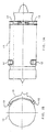
- Figs. 1A and 1B indicate the positions of front mounts 12 and rear mounts 14 relative to power plant 13.
- Mounts 12 and 14 are designed to attach power plant 13 to a support beam 15 which is, in turn attached to the aircraft's fusilage (not shown).
- initial testing is performed on the power plant 13 to determine its primary axis of vibration transmission.
- the primary trans-mission axes extend along two pairs of radial axes of the power plant 13 into mounts 12 and 14.
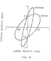
- Such information can be deduced from the graph in Fig. 1C in which the power plant in question was suspended by a conventional elastomeric mount which did not exhibit the directional softness which characterizes the present invention.
- the primary axis of the ellipse defining the loci of points on the vertical velocity vs horizontal velocity graph resulting from motion of the engine has a slope of 1 suggesting a radial transmission axis which is flattened into an ellipse by the lateral stiffhess of the combined airframe and mount.
- each mount 12, 14 can be designed to be statically soft in a first lateral (non-thrust) direction tangential to the power plant 13 (i.e., to have an elastomeric portion with a low shear stiffness).
- the mount is designed to have a higher static spring rate in the second lateral direction lying along the primary transmission path, with the elastomer loaded in compression and the particular spring rate related more to the weight support requirements than to the vibration isolation desired.
- the aft mount 14 will be designed to also be soft in the thrust direction so the primary thrust load is transmitted through the front mount 12 .
- the aft mount is designed to accept axial loading in shear (where the front mount is loaded in the fore and aft direction in compression) and is soft in shear to enable movement of the engine relative to the fusilage due to thermal expansion without loading the fusilage.
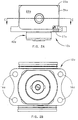
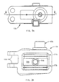
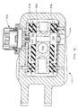
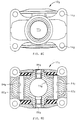
- FIG. 2A-D A first embodiment of a forward mount of the present invention is depicted in Figs. 2A-D generally at 12a.
- Forward mount 12a is attached to power plant 13 ( Fig. 1A ) by securing bolts through bolt holes 16a .
- a first elastomeric sandwich 18a is clamped against the forward surface 19a of mount 12a and a second elastomeric sandwich 20a is clamped against the aft surface 22a by sleeve 24a .
- Sleeve 24a is attached to surface plates 26a and 28a , as by swaging, or the like, plates 26a and 28a being laminated to the outer elastomeric surfaces of sandwiches 18a and 20a, respectively.
- a plurality of pins 29a are used to transmit tangential and radial shear from engine 13 (via the housing 31a) through pins 29a to sandwich elements 18a and 20a and then through plates 26a and 28a, to sleeve 24a and finally to support 15 by the mount's attachment bolt.
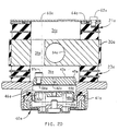
- a truncated-spherical (in cross section) piston element 30a is attached to sleeve 24a and moves within a similarly cross-sectioned chamber 32a in housing 31a acting as a piston to pump fluid between upper ( 34a ) and lower ( 36a ) chambers ( Fig. 2D ) through inertial track 38a .
- a third elastomeric sandwich element 21a is bonded to portions of the upper surface of the piston 30a and a fourth sandwich element 23a is bonded to the bottom portions of piston 30a .
- the tangential direction (across each Figure) has the softest spring rate because each of the four sandwich elements 18a , 20a , 21a and 23a is loaded in shear.
- the compressive stiffness of sandwich elements 18a and 20a in the fore and aft direction will be designed to be roughly twice that of the elements 21a and 23a on the top and bottom, the spring rate of the former being a function of the thrust of the engine and the spring rate of the latter a function of the engine's weight.
- a volume compensator 40a is positioned within pilot 41a and connected to one of the fluid chambers 34a , 36a and inertia track 38a by means of an isolation orifice 42a , shown here as being formed in plug 43a which is press fit into opening 45a.
- Isolation orifice 42a is of such a size as to dynamically isolate fluid chamber 44a of compensator 40a from the primary fluid system.
- Orifice 42a permits fluid displaced from the primary fluid system due to thermal expansion of the fluid to enter chamber 44a .
- An elastomeric bladder 46a separates fluid chamber 44a from pressurized pneumatic chamber 48a .
- a coil spring 50a may assist the applied fluid pressure in supporting the piston 52a . While spring 50a is shown in Fig.
- Sleeve 24a is received in opening 54a in truncated spherical element 30a .
- a through bolt (not shown) inserted through sleeve 24a attaches element 30a to support beam 15 .
- a plug 57a is threaded into orifice 58a which is the fill port for volume compensator 40a.
- Filling compensator 40a through isolation orifice 42a is not practical or possible because of its size, hence the use of fill port 58a .
- fill port 58a is in alignment with at least one of the inertia track 38a and the primary fill port (if any) for the primary fluid system. Accordingly, chamber 44a can be filled with fluid, a tool inserted through inertia track 38a to install plug 57a , the main fluid chambers 34a , 36a , 3 8a filled and the primary fill port plugged.
- face plate 60a is fastened in place using a plurality of bolts 62a to close the primary fill port (open top of chamber 34a ) compressing O-ring 64a to seal the fluid into chamber 34a .
- front mount 12a will be attached to engine 13 by bolts through apertures 16a and to support beam 15 by a bolt through sleeve 24a .
- Vibrations of engine 13 will be isolated from the support beam 15 by the relatively soft spring rate of the elastomer of sandwich elements 18a, 20a, 21a, 23a in shear for tangentially directed vibrations.
- the compressive spring rate of the elastomer in sandwiches 21a and 23a is sufficient to provide the support for the engine in the radial direction without undue engine deflection.
- the primary fluid system will be tuned to provide a dynamic softness, or notch, usually at the primary operational frequency, N 1 , of the engine.
- Tuning of the passive fluid system is done by varying the relevant parameters including density of the fluid, length and diameter of the passageway 38a, and volume stiffness of the primary fluid system. Tuning this dynamic stiffness notch to coincide with the primary vibrational input frequency will reduce the vibration transmitted at this most troublesome frequency.
- Mount 12a will have an effective dynamic stiffness in both the tangential and radial directions that will generally fall in the 122.6-140.1 DaN/mm (7000-8000 lb/in) range for the static stiffnesses described above at the N 1 tone. This will optimize isolation of the mount by minimizing the vibration transmitted across the mount.
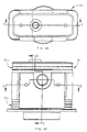
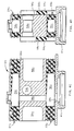
- FIG. 3A-C A second embodiment of the forward mount of the present invention is depicted in Figs. 3A-C generally at 12b .
- Forward mount 12b is attached to support structure (not shown) by a securing bolt received in openings 16b .
- Mount 12b is secured to engine 13 by attaching a securement bolt (not shown) through opening 54b in piston 30b .
- Volume compensator 40b is mounted on the top of mount 12b . While this mount embodiment may be filled in accordance with the method described in conjunction with the first embodiment finally inserting pop rivet plug 66b ( Fig.
- chambers 34b and 36b have more exotic shapes and provide an elastomeric coating for most internal metallic surfaces.
- a third embodiment is shown in Figs. 4A-E generally at 12c.
- This third embodiment 12c exhibits a configuration similar to that of the first embodiment 12a having cavities 34c and 36c .
- Sandwich elements 18c and 20c are bonded to the sides of piston 30c as opposed to simply being clamped to the exterior.
- Skirt 59c is formed on the outside of sandwich elements 18c and 20c to facilitate their manufacture.
- the internal portion of mount 12c can be dropped into housing 31c and pinned in place by pins 29c , bushings 61c installed in the front and aft portions of opening 54c , and mount 12c secured to engine 13 using slots 16c .
- the volume compensator may be installed in pilot 41c as in the first embodiment.
- FIG. 5 A fourth embodiment of the mount of the present invention is shown in Fig. 5 generally at 12d having cavities 34d and 36d .
- Plug 43d which is press fit into opening 45d , is much smaller in this embodiment and has isolation orifice 42d and a threaded passageway for receiving fill plug 57d formed therein.
- fill plug 63d for the main chambers 34d and 36d with inertia track 38d can be threaded into extruded port 65d compressing O-ring 64d to seal port 65d.
- FIG. 6A and 6B A fifth embodiment of the mount of the present invention is depicted in Figs. 6A and 6B generally at 12e .
- Key differences from previously described embodiments include the inclusion of volume compensator 40e in one of the weight reduction cavities 56e eliminating the need for a separately formed pilot.
- piston 52e is considerably smaller and oriented horizontally, spring 50e need not support its full weight nor the weight of its associated fluid. Accordingly, depending upon the level of pressurization required in the primary fluid system, chamber 48e may be opened to the atmosphere. If additional pressurization is necessary, chamber 48e can be pressurized and opening 58e plugged.
- Another feature which differs is the positioning of orifice-containing ( 42e ) plug 57e in an auxiliary passageway 67e accessible through port 65e without having to reach a tool through inertia track 38e .
- the isolation available with passive fluid systems is generally limited to a single frequency or band of frequencies. Vibrations transmitted at frequencies of operation outside that band will be reduced by passive fluid systems but to a much lesser extent. Accordingly, it is contemplated that an actuator could be added to the primary fluid system in order to effectively move the notch to correspond with the frequency of operation of the engine at any particular moment.
- Fig. 4F is Fig. 6 of the abovenoted patent with a '1' prefix used on common reference numerals.
- Actuator 136 is shown in Fig. 4F as positioned in an auxiliary housing 138.
- Auxiliary housing might take the form of a cover for a weight reduction cavity 56c in piston 30c with actuator 136 extending into inertia track 38c.
- Actuator 136 can be fastened in place by bolts 142 .
- actuator 136 is depicted as an electromagnetic actuator featuring magnet 144, pole piece 146 , voice coil 148 , spool 150 with centering springs 152 .
- the centering spring nearest the spool end 154 reacts against and is retained by circlip 153.
- Actuator 136 may be sealed in an opening 56c by an O-ring (not shown) and communicate with auxiliary chamber 36c through passageway 158 .
- Spool 150 is received in a self-lubricating bushing 151 which may be made of Rulon plastic, or the like.
- the laterally extending surface of voice coil 148 has a plurality of holes 149 therethrough to permit free flow of fluid within the actuator 136 . Without holes 149 , movement of voice coil 148 would be restricted due to trapping of the fluid between coil 148 and pole piece 146 .
- Conductive wire 147 usually copper, forms the windings of voice coil 148.
- An electromagnetic actuator of the type suitable for this application can be purchased from the Kimco Division of BEI Motion Systems in San Marcos, California.
- Housing 162 will be sealed within cavity 56c by an enclosing wall of auxiliary housing 138.
- a plurality of openings 164 in housing 162 provide fluid access between the voice coil 148 and passageway 158 .
- Spool 150 will "pump fluid" in response to movement of coil 148 resulting in energy being input into the fluid in chamber 36c altering the rate of fluid oscillation in the system.
- the passively generated forces of the mount e.g., the damping forces of the elastomer sandwich elements 21c and 23c and resistance to fluid flow in the system
- a sensor 181 may be mounted on engine 13 or the like to provide an input signal indicative of the disturbance signal to controller 183 .
- Controller 183 employs information about the disturbance signal to adjust the rate of movement of spool 150 to counter the vibrational input of the engine. Error sensors (not shown) may be used to further tweak the controller output signal to voice coil 148 .
- FIG. 7A and 7B An aft mount embodying the features of the present invention are depicted in Figs. 7A and 7B generally at 14f .
- Housing 31f is bolted to the frame using bolt holes 16f and the mount is affixed to the engine through throughbore 54f .
- the internal portions of mount 14f are virtually identical to those shown in Fig. 6B and have not been replicated here.
- the internal portion is pinned into housing 31f by shear transmission pins 29f .
- the piston 30f will alternately compress elastomeric sandwich elements 21f and 23f pumping fluid between upper and lower chambers (not shown) through a connecting inertia track.
- Piston 30g has an axial bore 70g extending therethrough.
- Actuator 72g is suspended by bracket 74g from the upper surface of piston 30g using bolts 76g .
- Actuator rod 78g of the actuator 72g extends through a hole 80g in bracket 74g and has a nut threaded 79g thereon.
- a pair of rods 82g extend through oversized holes 84g in piston 30g . Tangential and radial motions will be snubbed by the engagement of rods 82g with the sides of their respective holes 84g .
- a suitable actuator is available from Moog as C10193-1.
- This actuator 72g is, in effect, a tuned vibration absorber; that is, when the actuator is not turned on, it will still produce a notch at the N 1 frequency, by design. When turned on, actuator 72g will be able to produce a cancellation frequency over a range of input disturbance frequencies as was the case with the active fluid embodiment.
- Actuator 72g functions as an inertial non-fluid mass which will resonate at a design frequency (usually N 1 ) to produce an out-of-phase inertial effect sufficient to cancel the vibrational input from engine 13 associated with the primary input therefrom.
- actuator 72g When actuator 72g is activated responsive to a sensor, its operational frequency can be varied over the suggested range to provide out-of-phase cancelling vibrations extending over the operational frequency range of the engine.
Landscapes
- Engineering & Computer Science (AREA)
- General Engineering & Computer Science (AREA)
- Mechanical Engineering (AREA)
- Aviation & Aerospace Engineering (AREA)
- Combined Devices Of Dampers And Springs (AREA)
- Arrangement Or Mounting Of Propulsion Units For Vehicles (AREA)
Applications Claiming Priority (3)
| Application Number | Priority Date | Filing Date | Title |
|---|---|---|---|
| US606130 | 1996-02-23 | ||
| US08/606,130 US5762295A (en) | 1996-02-23 | 1996-02-23 | Dynamically optimized engine suspension system |
| EP97904791A EP0880452A4 (de) | 1996-02-23 | 1997-01-14 | Dynamisch 0ptimierte aufhängeanordnung eines fahrzeugmotors |
Related Parent Applications (1)
| Application Number | Title | Priority Date | Filing Date |
|---|---|---|---|
| EP97904791A Division EP0880452A4 (de) | 1996-02-23 | 1997-01-14 | Dynamisch 0ptimierte aufhängeanordnung eines fahrzeugmotors |
Publications (3)
| Publication Number | Publication Date |
|---|---|
| EP1296082A2 true EP1296082A2 (de) | 2003-03-26 |
| EP1296082A3 EP1296082A3 (de) | 2005-01-19 |
| EP1296082B1 EP1296082B1 (de) | 2006-04-05 |
Family
ID=24426675
Family Applications (2)
| Application Number | Title | Priority Date | Filing Date |
|---|---|---|---|
| EP02027249A Expired - Lifetime EP1296082B1 (de) | 1996-02-23 | 1997-01-14 | Dynamisch optimisiertes Motoraufhängungssystem |
| EP97904791A Withdrawn EP0880452A4 (de) | 1996-02-23 | 1997-01-14 | Dynamisch 0ptimierte aufhängeanordnung eines fahrzeugmotors |
Family Applications After (1)
| Application Number | Title | Priority Date | Filing Date |
|---|---|---|---|
| EP97904791A Withdrawn EP0880452A4 (de) | 1996-02-23 | 1997-01-14 | Dynamisch 0ptimierte aufhängeanordnung eines fahrzeugmotors |
Country Status (4)
| Country | Link |
|---|---|
| US (1) | US5762295A (de) |
| EP (2) | EP1296082B1 (de) |
| DE (1) | DE69735650T2 (de) |
| WO (1) | WO1997030895A1 (de) |
Cited By (4)
| Publication number | Priority date | Publication date | Assignee | Title |
|---|---|---|---|---|
| FR2934245A1 (fr) * | 2008-07-24 | 2010-01-29 | Airbus France | Aeronef comprenant un moteur commande par synchrophasage |
| FR2934246A1 (fr) * | 2008-07-24 | 2010-01-29 | Airbus France | Aeronef comprenant au moins un moteur a rotors contrarotatifs |
| US7946163B2 (en) | 2007-04-02 | 2011-05-24 | Penske Racing Shocks | Methods and apparatus for developing a vehicle suspension |
| WO2021126186A1 (en) * | 2019-12-18 | 2021-06-24 | Lord Corporation | Ultra-high temperature elastomeric alignment & isolation devices |
Families Citing this family (31)
| Publication number | Priority date | Publication date | Assignee | Title |
|---|---|---|---|---|
| US5957440A (en) * | 1997-04-08 | 1999-09-28 | Lord Corporation | Active fluid mounting |
| US6092795A (en) * | 1997-08-04 | 2000-07-25 | Lord Corporation | Fluid and elastomer damper |
| US5954169A (en) * | 1997-10-24 | 1999-09-21 | Lord Corporation | Adaptive tuned vibration absorber, system utilizing same and method of controlling vibration therewith |
| US6394432B1 (en) * | 1998-06-10 | 2002-05-28 | Lord Corporation | Vibration and/or shock absorbing devices and compensator elements utilized therein |
| DE19828311C2 (de) * | 1998-06-25 | 2002-05-16 | Mannesmann Boge Gmbh | Hydraulisch dämpfendes Motorlager |
| US6328293B1 (en) | 1998-09-18 | 2001-12-11 | Lord Corporation | Multi-linkage suspension system including outboard isolators |
| US6045328A (en) * | 1998-09-23 | 2000-04-04 | Lord Corporation | Fluid damper including flexible damping plate |
| WO2002008629A2 (en) | 2000-07-21 | 2002-01-31 | Lord Corpoation | Vibration isolation device with load dependent stiffness |
| WO2002040347A2 (en) * | 2000-09-27 | 2002-05-23 | Lord Corporation | Mounting assembly for an aircraft auxiliary power unit |
| US6378851B1 (en) | 2000-10-25 | 2002-04-30 | Lord Corporation | Fluid and elastomer apparatus with discrete volume compensator and secondary compliance |
| US6659438B2 (en) | 2002-03-04 | 2003-12-09 | Lord Corporation | Mount with dual stiffness |
| CA2489103C (en) * | 2002-06-07 | 2009-03-31 | Boart Longyear Limited | Vibration isolator |
| EP1378444B1 (de) * | 2002-07-01 | 2011-01-05 | Barry Controls Corp. | Zwei-Ton Schwingungsdämpfer |
| US6758466B2 (en) * | 2002-11-06 | 2004-07-06 | Lord Corporation | Fluid-elastomeric damper assembly including internal pumping mechanism |
| US7270321B2 (en) * | 2002-11-06 | 2007-09-18 | Lord Corporation | Fluid-elastomeric damper assembly including internal pumping mechanism |
| JP4078321B2 (ja) * | 2004-03-11 | 2008-04-23 | 本田技研工業株式会社 | 能動型防振支持装置 |
| US20060032974A1 (en) * | 2004-08-16 | 2006-02-16 | Honeywell International Inc. | Modular installation kit for auxiliary power unit |
| EP1954958A1 (de) * | 2005-11-28 | 2008-08-13 | Lord Corporation | Isolierter achsenstossdämpfer zur unterstützung einer achsenladung und dämpfer für den achsenstossdämpfer |
| US8113321B2 (en) * | 2006-05-06 | 2012-02-14 | Lord Corporation | Helicopter reduced vibration isolator axial support strut |
| US8403115B2 (en) | 2008-01-11 | 2013-03-26 | Penske Racing Shocks | Dual rate gas spring shock absorber |
| FR2939103B1 (fr) * | 2008-12-01 | 2011-01-21 | Airbus France | Systeme hydraulique de transmission d'efforts entre un turbopropulseur d'aeronef et un dispositif d'accrochage |
| US8256750B2 (en) * | 2009-02-18 | 2012-09-04 | Honeywell International Inc. | Vibration isolation mounting assembly |
| US8272786B2 (en) * | 2009-02-18 | 2012-09-25 | Honeywell International Inc. | Vibration isolation mounting assembly |
| US8702377B2 (en) | 2010-06-23 | 2014-04-22 | Honeywell International Inc. | Gas turbine engine rotor tip clearance and shaft dynamics system and method |
| FR2965850B1 (fr) * | 2010-10-11 | 2012-12-14 | Airbus Operations Sas | Dispositif de liaison de securite et aeronef equipe d'un tel dispositif de liaison de securite |
| US9399508B2 (en) | 2013-10-09 | 2016-07-26 | The Boeing Company | Aircraft wing-to-fuselage joint with active suspension and method |
| US10550907B2 (en) | 2016-08-18 | 2020-02-04 | Textron Innovations Inc. | Liquid inertia vibration elimination system |
| FR3059645B1 (fr) | 2016-12-02 | 2018-12-07 | Safran Aircraft Engines | Dispositif de suspension pour turbomachine |
| US10875655B2 (en) * | 2017-06-23 | 2020-12-29 | Hutchinson Aerospace & Industry Inc. | Vibration isolation device, especially for aircraft applications |
| FR3088902B1 (fr) | 2018-11-27 | 2020-11-06 | Safran Aircraft Engines | Assemblage pour ensemble moteur d’aéronef, comprenant une fonction anti-rotation améliorée |
| US11440648B2 (en) * | 2020-04-22 | 2022-09-13 | Textron Innovations Inc. | Compact vibration isolation systems for aircraft |
Citations (2)
| Publication number | Priority date | Publication date | Assignee | Title |
|---|---|---|---|---|
| US4962915A (en) | 1989-07-18 | 1990-10-16 | Lord Corporation | Three-axis fluid-filled mount |
| US5413320A (en) | 1993-06-17 | 1995-05-09 | Lord Corporation | Fluid mount for devices such as engines |
Family Cites Families (38)
| Publication number | Priority date | Publication date | Assignee | Title |
|---|---|---|---|---|
| US2297506A (en) * | 1940-10-05 | 1942-09-29 | Schmidt Fritz | Elastic mounting |
| US2421585A (en) * | 1944-12-13 | 1947-06-03 | Gen Tire & Rubber Co | Fluid-modified mounting |
| US3018990A (en) * | 1958-07-15 | 1962-01-30 | Daimler Benz Ag | Elastic engine suspension especially for motor vehicles |
| US2919883A (en) * | 1958-12-11 | 1960-01-05 | Bendix Aviat Corp | Liquid damped vibration isolator |
| US3132830A (en) * | 1961-07-14 | 1964-05-12 | Gen Motors Corp | Resilient mountings for motor vehicle power units |
| US3487888A (en) * | 1966-08-22 | 1970-01-06 | Mc Donnell Douglas Corp | Cabin engine sound suppressor |
| US4111386A (en) * | 1976-12-09 | 1978-09-05 | United Technologies Corporation | Helicopter rotor and transmission mounting and vibration isolation system |
| GB2018942B (en) * | 1978-03-20 | 1982-06-03 | Aerospatiale | Multi-directional suspension means |
| US4236607A (en) * | 1979-02-26 | 1980-12-02 | Textron, Inc. | Vibration suppression system |
| DE3024090C1 (de) * | 1980-06-27 | 1981-10-01 | Boge Gmbh, 5208 Eitorf | Motorlager fuer Lastkraftwagen,Omnibusse o.dgl. Nutzfahrzeuge |
| JPS5728931U (de) * | 1980-07-25 | 1982-02-16 | ||
| DE3433255C2 (de) * | 1984-09-11 | 1987-01-02 | Fa. Carl Freudenberg, 6940 Weinheim | Schwingungsdämpfendes Lager |
| DE3521246A1 (de) * | 1985-06-13 | 1987-01-02 | Kaspar Lochner | Elastisches lager |
| US4811919A (en) * | 1987-08-06 | 1989-03-14 | Lord Corporation | Volume compensated fluid mount |
| US4805851A (en) * | 1987-08-10 | 1989-02-21 | Herbst Paul T | Turbine engine mounting bracket assembly |
| IT1237779B (it) * | 1989-11-20 | 1993-06-17 | Pirelli Sistemi Antivibranti | Supporto motore. |
| US5423523A (en) * | 1990-04-09 | 1995-06-13 | Noise Cancellation Technologies, Inc. | Integrated hydraulic mount for active vibration control system |
| JPH0442937U (de) * | 1990-08-09 | 1992-04-13 | ||
| JPH04219542A (ja) * | 1990-10-11 | 1992-08-10 | Bridgestone Corp | 防振装置 |
| DE4041837C1 (de) * | 1990-12-24 | 1992-04-30 | Boge Ag, 5208 Eitorf, De | |
| US5186485A (en) * | 1991-04-01 | 1993-02-16 | Paccar, Inc. | Vehicle suspension |
| FR2675558A1 (fr) * | 1991-04-22 | 1992-10-23 | Hutchinson | Barre elastique de liaison a systeme de controle actif des vibrations. |
| JP2618767B2 (ja) * | 1991-05-17 | 1997-06-11 | 東海ゴム工業株式会社 | ステアリングカップリング |
| US5197692A (en) * | 1991-05-29 | 1993-03-30 | Lord Corporation | Adaptive fluid mount |
| US5176339A (en) * | 1991-09-30 | 1993-01-05 | Lord Corporation | Resilient pivot type aircraft mounting |
| US5174552A (en) * | 1991-10-15 | 1992-12-29 | Lord Corporation | Fluid mount with active vibration control |
| US5176368A (en) * | 1992-01-13 | 1993-01-05 | Trw Inc. | Vehicle engine mount |
| US5312093A (en) * | 1992-01-28 | 1994-05-17 | Applied Power Inc. | Vibration isolator with two pairs of fluid chambers with diagonal fluid communication |
| US5273261A (en) * | 1992-04-17 | 1993-12-28 | General Motors Corporation | Hydraulic torque strut with decoupling and related mounting system |
| US6022600A (en) * | 1992-04-24 | 2000-02-08 | Lord Corporation | High-temperature fluid mounting |
| US5351930A (en) * | 1992-08-11 | 1994-10-04 | Lord Corporation | Mounting for engines and the like |
| US5374039A (en) * | 1992-08-24 | 1994-12-20 | Lord Corporation | Fluid-and-elastomer support device |
| US5363700A (en) * | 1992-11-17 | 1994-11-15 | Honeywell Inc. | Skewed axis inertial sensor assembly |
| GB9305474D0 (en) * | 1993-03-17 | 1993-05-05 | Jaguar Cars | Gearbox mounting |
| US5427347A (en) * | 1993-04-08 | 1995-06-27 | Lord Corporation | Apparatus for controlling active mounts |
| US5551650A (en) * | 1994-06-16 | 1996-09-03 | Lord Corporation | Active mounts for aircraft engines |
| DE69514246T2 (de) * | 1994-10-12 | 2000-05-31 | Lord Corp., Cary | Aktivsysteme und vorrichtungen inklusive aktivschwingungsdämpfern |
| US5526292A (en) * | 1994-11-30 | 1996-06-11 | Lord Corporation | Broadband noise and vibration reduction |
-
1996
- 1996-02-23 US US08/606,130 patent/US5762295A/en not_active Expired - Lifetime
-
1997
- 1997-01-14 EP EP02027249A patent/EP1296082B1/de not_active Expired - Lifetime
- 1997-01-14 DE DE69735650T patent/DE69735650T2/de not_active Expired - Lifetime
- 1997-01-14 WO PCT/US1997/000727 patent/WO1997030895A1/en not_active Ceased
- 1997-01-14 EP EP97904791A patent/EP0880452A4/de not_active Withdrawn
Patent Citations (2)
| Publication number | Priority date | Publication date | Assignee | Title |
|---|---|---|---|---|
| US4962915A (en) | 1989-07-18 | 1990-10-16 | Lord Corporation | Three-axis fluid-filled mount |
| US5413320A (en) | 1993-06-17 | 1995-05-09 | Lord Corporation | Fluid mount for devices such as engines |
Non-Patent Citations (1)
| Title |
|---|
| us08260945 a |
Cited By (11)
| Publication number | Priority date | Publication date | Assignee | Title |
|---|---|---|---|---|
| US7946163B2 (en) | 2007-04-02 | 2011-05-24 | Penske Racing Shocks | Methods and apparatus for developing a vehicle suspension |
| FR2934245A1 (fr) * | 2008-07-24 | 2010-01-29 | Airbus France | Aeronef comprenant un moteur commande par synchrophasage |
| FR2934246A1 (fr) * | 2008-07-24 | 2010-01-29 | Airbus France | Aeronef comprenant au moins un moteur a rotors contrarotatifs |
| WO2010010292A3 (fr) * | 2008-07-24 | 2010-03-18 | Airbus Operations | Aeronef comprenant au moins un moteur a rotors contrarotatifs |
| WO2010010293A3 (fr) * | 2008-07-24 | 2010-03-18 | Airbus Operations | Aeronef comprenant un moteur commande par synchrophasage |
| CN102159463A (zh) * | 2008-07-24 | 2011-08-17 | 空中客车运营事务 | 包括至少一个具有反转桨的发动机的航空器 |
| CN102159463B (zh) * | 2008-07-24 | 2013-08-07 | 空中客车运营简化股份公司 | 包括至少一个具有反转桨的发动机的航空器 |
| CN102159462B (zh) * | 2008-07-24 | 2013-12-25 | 空中客车运营简化股份公司 | 包括同步定相控制的发动机的航空器 |
| US8740133B2 (en) | 2008-07-24 | 2014-06-03 | Airbus Operations | Aircraft including an engine controlled by synchrophasing |
| US9085372B2 (en) | 2008-07-24 | 2015-07-21 | Airbus Operations Sas | Aircraft comprising at least one engine having contra-rotating rotors |
| WO2021126186A1 (en) * | 2019-12-18 | 2021-06-24 | Lord Corporation | Ultra-high temperature elastomeric alignment & isolation devices |
Also Published As
| Publication number | Publication date |
|---|---|
| EP1296082A3 (de) | 2005-01-19 |
| US5762295A (en) | 1998-06-09 |
| EP0880452A1 (de) | 1998-12-02 |
| EP1296082B1 (de) | 2006-04-05 |
| DE69735650T2 (de) | 2006-08-24 |
| EP0880452A4 (de) | 2002-02-06 |
| DE69735650D1 (de) | 2006-05-18 |
| WO1997030895A1 (en) | 1997-08-28 |
Similar Documents
| Publication | Publication Date | Title |
|---|---|---|
| EP1296082B1 (de) | Dynamisch optimisiertes Motoraufhängungssystem | |
| US5174552A (en) | Fluid mount with active vibration control | |
| CA2186453C (en) | Hydraulic inertial vibration isolator | |
| US20020128072A1 (en) | Active system and method for vibration and noise reduction | |
| CA1320711C (en) | Volume compensated fluid mount | |
| EP0621418B1 (de) | Einrichtung zur Regelung von aktiven Lagern | |
| EP0852678B1 (de) | System zur schwingungsisolation, das einen passiv abgestimmten schwingungsdämpfer enthält | |
| EP0524236B1 (de) | Integriertes hydraulisches lager für aktives schwingungsdämpfungssystem | |
| EP1866555B1 (de) | Schwingungsdämpfung | |
| US6431530B1 (en) | Vertical liquid inertia vibration isolator | |
| US5626332A (en) | Vibration isolation system using plural signals for control | |
| US4974819A (en) | Mount for controlling or isolating vibration | |
| US5984062A (en) | Method for controlling an active truss element for vibration suppression | |
| EP0322239B1 (de) | Hydraulisch gedämpfte Lagervorrichtung | |
| CA1311772C (en) | Mount for controlling or isolating vibration | |
| EP0623197B1 (de) | Elasto-hydraulischer schwingungsisolator | |
| US20040140149A1 (en) | Passive device for noise reduction | |
| CA2244991A1 (en) | Dynamically optimized engine suspension system | |
| US5428582A (en) | Decoupling ring | |
| US20020100650A1 (en) | Hydraulic actuator | |
| JP2697298B2 (ja) | 電気粘性流体封入式防振装置 | |
| JPS6150827A (ja) | 防振装置 | |
| JPH05310196A (ja) | 宇宙航行体搭載機器の防振装置 | |
| JPH01120453A (ja) | 動吸振器 | |
| JP2000257661A (ja) | 油圧緩衝器 |
Legal Events
| Date | Code | Title | Description |
|---|---|---|---|
| PUAI | Public reference made under article 153(3) epc to a published international application that has entered the european phase |
Free format text: ORIGINAL CODE: 0009012 |
|
| 17P | Request for examination filed |
Effective date: 20021213 |
|
| AC | Divisional application: reference to earlier application |
Ref document number: 0880452 Country of ref document: EP Kind code of ref document: P |
|
| AK | Designated contracting states |
Kind code of ref document: A2 Designated state(s): DE FR GB IT |
|
| PUAL | Search report despatched |
Free format text: ORIGINAL CODE: 0009013 |
|
| AK | Designated contracting states |
Kind code of ref document: A3 Designated state(s): DE FR GB IT |
|
| RIC1 | Information provided on ipc code assigned before grant |
Ipc: 7F 16F 13/08 B Ipc: 7B 64D 27/00 A Ipc: 7F 16F 13/18 B Ipc: 7B 64D 27/26 B Ipc: 7F 16F 9/43 B |
|
| GRAP | Despatch of communication of intention to grant a patent |
Free format text: ORIGINAL CODE: EPIDOSNIGR1 |
|
| AKX | Designation fees paid |
Designated state(s): DE FR GB IT |
|
| GRAS | Grant fee paid |
Free format text: ORIGINAL CODE: EPIDOSNIGR3 |
|
| GRAA | (expected) grant |
Free format text: ORIGINAL CODE: 0009210 |
|
| AC | Divisional application: reference to earlier application |
Ref document number: 0880452 Country of ref document: EP Kind code of ref document: P |
|
| AK | Designated contracting states |
Kind code of ref document: B1 Designated state(s): DE FR GB IT |
|
| PG25 | Lapsed in a contracting state [announced via postgrant information from national office to epo] |
Ref country code: IT Free format text: LAPSE BECAUSE OF FAILURE TO SUBMIT A TRANSLATION OF THE DESCRIPTION OR TO PAY THE FEE WITHIN THE PRESCRIBED TIME-LIMIT;WARNING: LAPSES OF ITALIAN PATENTS WITH EFFECTIVE DATE BEFORE 2007 MAY HAVE OCCURRED AT ANY TIME BEFORE 2007. THE CORRECT EFFECTIVE DATE MAY BE DIFFERENT FROM THE ONE RECORDED. Effective date: 20060405 |
|
| REG | Reference to a national code |
Ref country code: GB Ref legal event code: FG4D |
|
| REF | Corresponds to: |
Ref document number: 69735650 Country of ref document: DE Date of ref document: 20060518 Kind code of ref document: P |
|
| ET | Fr: translation filed | ||
| PLBE | No opposition filed within time limit |
Free format text: ORIGINAL CODE: 0009261 |
|
| STAA | Information on the status of an ep patent application or granted ep patent |
Free format text: STATUS: NO OPPOSITION FILED WITHIN TIME LIMIT |
|
| 26N | No opposition filed |
Effective date: 20070108 |
|
| GBPC | Gb: european patent ceased through non-payment of renewal fee |
Effective date: 20070114 |
|
| PG25 | Lapsed in a contracting state [announced via postgrant information from national office to epo] |
Ref country code: GB Free format text: LAPSE BECAUSE OF NON-PAYMENT OF DUE FEES Effective date: 20070114 |
|
| PGFP | Annual fee paid to national office [announced via postgrant information from national office to epo] |
Ref country code: IT Payment date: 20140110 Year of fee payment: 18 |
|
| PGFP | Annual fee paid to national office [announced via postgrant information from national office to epo] |
Ref country code: DE Payment date: 20150106 Year of fee payment: 19 |
|
| REG | Reference to a national code |
Ref country code: FR Ref legal event code: PLFP Year of fee payment: 20 |
|
| PG25 | Lapsed in a contracting state [announced via postgrant information from national office to epo] |
Ref country code: IT Free format text: LAPSE BECAUSE OF NON-PAYMENT OF DUE FEES Effective date: 20150114 |
|
| PGFP | Annual fee paid to national office [announced via postgrant information from national office to epo] |
Ref country code: FR Payment date: 20151208 Year of fee payment: 20 |
|
| REG | Reference to a national code |
Ref country code: DE Ref legal event code: R119 Ref document number: 69735650 Country of ref document: DE |
|
| PG25 | Lapsed in a contracting state [announced via postgrant information from national office to epo] |
Ref country code: DE Free format text: LAPSE BECAUSE OF NON-PAYMENT OF DUE FEES Effective date: 20160802 |