EP1296866B1 - Systeme de freinage electrohydraulique pour automobiles - Google Patents
Systeme de freinage electrohydraulique pour automobiles Download PDFInfo
- Publication number
- EP1296866B1 EP1296866B1 EP01943503A EP01943503A EP1296866B1 EP 1296866 B1 EP1296866 B1 EP 1296866B1 EP 01943503 A EP01943503 A EP 01943503A EP 01943503 A EP01943503 A EP 01943503A EP 1296866 B1 EP1296866 B1 EP 1296866B1
- Authority
- EP
- European Patent Office
- Prior art keywords
- separating valve
- electro
- brake system
- actuation
- hydraulic
- Prior art date
- Legal status (The legal status is an assumption and is not a legal conclusion. Google has not performed a legal analysis and makes no representation as to the accuracy of the status listed.)
- Expired - Lifetime
Links
- 238000012544 monitoring process Methods 0.000 claims description 9
- 230000001105 regulatory effect Effects 0.000 claims description 7
- 230000035484 reaction time Effects 0.000 claims 1
- 238000002955 isolation Methods 0.000 description 12
- 230000000903 blocking effect Effects 0.000 description 3
- 238000010586 diagram Methods 0.000 description 3
- 238000011156 evaluation Methods 0.000 description 3
- 230000004913 activation Effects 0.000 description 2
- 238000001514 detection method Methods 0.000 description 2
- 238000011161 development Methods 0.000 description 2
- 230000003213 activating effect Effects 0.000 description 1
- 238000004891 communication Methods 0.000 description 1
- 230000001276 controlling effect Effects 0.000 description 1
- 230000002950 deficient Effects 0.000 description 1
- 239000012530 fluid Substances 0.000 description 1
- 230000007257 malfunction Effects 0.000 description 1
- 238000000034 method Methods 0.000 description 1
- 238000011144 upstream manufacturing Methods 0.000 description 1
Images

Classifications
-
- B—PERFORMING OPERATIONS; TRANSPORTING
- B60—VEHICLES IN GENERAL
- B60T—VEHICLE BRAKE CONTROL SYSTEMS OR PARTS THEREOF; BRAKE CONTROL SYSTEMS OR PARTS THEREOF, IN GENERAL; ARRANGEMENT OF BRAKING ELEMENTS ON VEHICLES IN GENERAL; PORTABLE DEVICES FOR PREVENTING UNWANTED MOVEMENT OF VEHICLES; VEHICLE MODIFICATIONS TO FACILITATE COOLING OF BRAKES
- B60T8/00—Arrangements for adjusting wheel-braking force to meet varying vehicular or ground-surface conditions, e.g. limiting or varying distribution of braking force
- B60T8/32—Arrangements for adjusting wheel-braking force to meet varying vehicular or ground-surface conditions, e.g. limiting or varying distribution of braking force responsive to a speed condition, e.g. acceleration or deceleration
- B60T8/34—Arrangements for adjusting wheel-braking force to meet varying vehicular or ground-surface conditions, e.g. limiting or varying distribution of braking force responsive to a speed condition, e.g. acceleration or deceleration having a fluid pressure regulator responsive to a speed condition
- B60T8/40—Arrangements for adjusting wheel-braking force to meet varying vehicular or ground-surface conditions, e.g. limiting or varying distribution of braking force responsive to a speed condition, e.g. acceleration or deceleration having a fluid pressure regulator responsive to a speed condition comprising an additional fluid circuit including fluid pressurising means for modifying the pressure of the braking fluid, e.g. including wheel driven pumps for detecting a speed condition, or pumps which are controlled by means independent of the braking system
- B60T8/4072—Systems in which a driver input signal is used as a control signal for the additional fluid circuit which is normally used for braking
- B60T8/4081—Systems with stroke simulating devices for driver input
-
- B—PERFORMING OPERATIONS; TRANSPORTING
- B60—VEHICLES IN GENERAL
- B60T—VEHICLE BRAKE CONTROL SYSTEMS OR PARTS THEREOF; BRAKE CONTROL SYSTEMS OR PARTS THEREOF, IN GENERAL; ARRANGEMENT OF BRAKING ELEMENTS ON VEHICLES IN GENERAL; PORTABLE DEVICES FOR PREVENTING UNWANTED MOVEMENT OF VEHICLES; VEHICLE MODIFICATIONS TO FACILITATE COOLING OF BRAKES
- B60T13/00—Transmitting braking action from initiating means to ultimate brake actuator with power assistance or drive; Brake systems incorporating such transmitting means, e.g. air-pressure brake systems
- B60T13/10—Transmitting braking action from initiating means to ultimate brake actuator with power assistance or drive; Brake systems incorporating such transmitting means, e.g. air-pressure brake systems with fluid assistance, drive, or release
- B60T13/66—Electrical control in fluid-pressure brake systems
- B60T13/68—Electrical control in fluid-pressure brake systems by electrically-controlled valves
- B60T13/686—Electrical control in fluid-pressure brake systems by electrically-controlled valves in hydraulic systems or parts thereof
-
- B—PERFORMING OPERATIONS; TRANSPORTING
- B60—VEHICLES IN GENERAL
- B60T—VEHICLE BRAKE CONTROL SYSTEMS OR PARTS THEREOF; BRAKE CONTROL SYSTEMS OR PARTS THEREOF, IN GENERAL; ARRANGEMENT OF BRAKING ELEMENTS ON VEHICLES IN GENERAL; PORTABLE DEVICES FOR PREVENTING UNWANTED MOVEMENT OF VEHICLES; VEHICLE MODIFICATIONS TO FACILITATE COOLING OF BRAKES
- B60T7/00—Brake-action initiating means
- B60T7/02—Brake-action initiating means for personal initiation
- B60T7/04—Brake-action initiating means for personal initiation foot actuated
- B60T7/06—Disposition of pedal
-
- B—PERFORMING OPERATIONS; TRANSPORTING
- B60—VEHICLES IN GENERAL
- B60T—VEHICLE BRAKE CONTROL SYSTEMS OR PARTS THEREOF; BRAKE CONTROL SYSTEMS OR PARTS THEREOF, IN GENERAL; ARRANGEMENT OF BRAKING ELEMENTS ON VEHICLES IN GENERAL; PORTABLE DEVICES FOR PREVENTING UNWANTED MOVEMENT OF VEHICLES; VEHICLE MODIFICATIONS TO FACILITATE COOLING OF BRAKES
- B60T8/00—Arrangements for adjusting wheel-braking force to meet varying vehicular or ground-surface conditions, e.g. limiting or varying distribution of braking force
- B60T8/32—Arrangements for adjusting wheel-braking force to meet varying vehicular or ground-surface conditions, e.g. limiting or varying distribution of braking force responsive to a speed condition, e.g. acceleration or deceleration
- B60T8/321—Arrangements for adjusting wheel-braking force to meet varying vehicular or ground-surface conditions, e.g. limiting or varying distribution of braking force responsive to a speed condition, e.g. acceleration or deceleration deceleration
Definitions
- the invention relates to an electrohydraulic brake system for motor vehicles, which can be controlled in a "brake-by-wire" operating mode both by the vehicle driver and independently of the vehicle driver, and which can be operated in a fallback mode in which only operation by the vehicle driver is possible ,
- an emergency pressure transmitter or master brake cylinder which can be actuated by means of a brake pedal and has at least one pressure chamber
- a path simulator which interacts with the master brake cylinder and can be switched off by actuating the master brake cylinder
- a hydraulic auxiliary pressure source the pressure of which can be applied to wheel brakes, which can be connected to the master brake cylinder via at least one hydraulic connection that can be shut off by means of a separating valve, and an electronic control and regulating unit.
- Such an electro-hydraulic brake system is. E.g. from the technical article "The electro-hydraulic braking system from Continental Teves - a new challenge for the system and Method development in series ", VDI reports No. 1547, 2000, known.
- the isolating valves are used in the previously known brake system when the brake pedal is actuated by control signals in their closed position switched by the electronic Control and regulation unit are generated.
- the path simulator will in the event of a failure of the control or on-board electronics by the Movement of one of the master cylinder pistons mechanically blocked, so that the path simulator when actuating the master brake cylinder cannot absorb pressure medium volume in emergency braking mode.
- This object is achieved in that a additional electrical circuit is provided which occurs when it occurs independent of the driver deceleration request controlled by the electronic control unit.
- the response time of the electrical circuit is essential shorter than that of the electronic control unit.
- the electrical circuit is an evaluation circuit for detection of the driver delay request, which the release of Control plus the control of the isolating valve.
- An advantageous development of the subject matter of the invention consists in the fact that the evaluation circuit is followed by a timer is that generates a control signal for the isolation valve and which after a predetermined period of time Control of the isolating valve suppressed.
- a second safety function can be implemented that the electronic control unit a hardware monitoring circuit (Watchdog) is connected, which at a deviation of one from the electronic control unit generated dynamic state signal from one of the hardware monitoring circuit (watchdog) generated status signal suppresses the activation of the isolating valve.
- Watchdog a hardware monitoring circuit
- the aforementioned control of the isolating valve takes place preferably by means of two control logic circuits that one Safety switch and a cut-off valve driver assigned are connected in series with the isolating valve.
- the electro-hydraulic brake system shown in Fig. 1 consists of an actuatable by means of an actuation pedal 1, two-circuit master cylinder or tandem master cylinder 2, which interacts with a pedal travel simulator 3 and two by means of two master cylinder pistons has separate pressure rooms with an unpressurized Pressure fluid reservoir 4 are in communication.
- a connection between path simulator 3 and pressure medium reservoir 4 is not specified in the movement of the second master cylinder piston by means of a not shown Valve device shut off.
- first pressure chamber primary pressure chamber
- first hydraulic line 5 for example connected to the front axle wheel brakes 7.8.
- the line 5 is shut off by means of a first isolating valve 11, while switched between the wheel brakes 7, 8 Line section 12 an electromagnetically actuated, preferably normally open (SO) pressure compensation valve 13 is inserted, which is a bike individual if necessary Brake pressure control enables.
- SO normally open
- switched line section 16 is on again Electromagnetically operated, preferably open when de-energized (SO) pressure compensation valve 19 inserted. Since the structure of the the second pressure chamber of the master cylinder 2 connected hydraulic circuit identical to that in the previous one Description of the explained brake circuit 11 corresponds, it need no longer be discussed in the text below.
- an external pressure source serving motor-pump unit 20 with a High-pressure accumulator 21 is provided, which in turn consists of a by means of an electric motor 22 driven pump 23 and one of the pump 23 connected in parallel pressure relief valve 24 exists.
- the suction side of the pump 23 is via a check valve 24 to the pressure medium reservoir mentioned above 4 connected.
- the hydraulic applied by the pump 23 Pressure can be from a pressure sensor, not shown be monitored.
- a third hydraulic line 26 connects the high pressure accumulator 21 with the input terminals of two electromagnetic similarly controllable, normally closed 2/2-way valves 17, 18, the wheel brakes 7 as inlet valves and 8 are connected upstream.
- the wheel brakes 7, 8 via one electromagnetically controllable, currentless closed 2/2-way valve or outlet valve 27, 28 to one fourth hydraulic line 29 connected, on the other hand with the pressureless pressure medium reservoir 4 in connection stands.
- the hydraulic prevailing in the wheel brakes 7, 8 Pressure is determined using one pressure sensor 30, 31 each.
- the common control of the motor-pump unit 20 and the solenoid valves 11, 13, 14, 17, 18, 19, 27, 28 are used an electronic control unit (ECU) 32, which as Input signals the output signals of one with the operating pedal 1 interacting actuation travel sensor 33 and of the aforementioned pressure sensor 15 are supplied and the enable driver deceleration request recognition.
- ECU electronice control unit
- Input variables are the electronic control unit (ECU) 32 the output signals of the pressure sensors 30, 31 as well as the wheel speed sensors indicated only schematically fed, the associated with the wheel brakes 7,8 Provide wheel speed sensors with the reference numbers 34, 35 are.
- the control unit (ECU) 32 also receives Signals from an additional electrical circuit 36, the one independent of the control and regulating unit (ECU) 32, rapid control of the isolation valves 11, 14 is used.
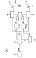
- FIG. 2 The structure of the electrical mentioned in connection with FIG. 1 Circuit 36 is shown in FIG. 2.
- the one shown in it Wiring diagram shows that this is the driver's delay request representative signal FVW of the actuation travel sensor 33 is fed to an evaluation circuit 40, a start signal S for activating a timer 41 Release signal F for a first control logic circuit 42 and a second drive logic circuit 43 and a wake-up signal W to "wake up" the control unit (ECU) 32.
- the first control logic circuit 42 is a safety switch 45 assigned while the second drive logic circuit 43 the control of an isolating valve driver 46 serves, both the safety switch 45 and the Isolation valve driver 46 with the coil to be driven the corresponding one Isolation valve 11, 14 are connected in series.
- the Timer 41 which contains a fixed time, serves the time limit of the activation of the control logic circuits 42, 43 in such a way that after the expiry of the predetermined Time a blocking signal S1 to switch off the control logic circuits 42, 43 generated.
- the control of the isolation valves 11, 14 is then controlled by the electronic and Control unit 32 taken over.
- the timer 41 is defective, there is a second safety function necessary with a malfunction the system switches off the isolation valves 11, 14 again.
- the second security function can, for example, by a second or redundant timer can be guaranteed.
- Another solution is to use one of the tax and control unit (ECU) 32 downstream hardware monitoring circuit (Watchdog) 44.
- the hardware monitoring circuit (Watchdog) 44 becomes one of the control and Control unit (ECU) 32 generated dynamic status signal WD fed that information about the state of the tax and Control unit (ECU) 32 contains and in the hardware monitoring circuit (Watchdog) 44 with an internally generated Status signal is compared in terms of time and value. If the status signals mentioned do not match, generated the hardware monitoring circuit (watchdog) 44 a second Lock signal S2 for switching off the control logic circuits 42, 43.
- the two blocking signals S1, S2 are preferred as input signals to a pair of logical OR gates 47, 48 supplied by the output signals, the control logic circuits 42, 43 are blocked.
- isolation valves 11, 14 of the two hydraulic Circles actuated by the control circuit. in principle it would be sufficient to use only the isolation valve 14, which of the Secondary pressure chamber leads to the wheel brakes 9, 10 to control.
Landscapes
- Engineering & Computer Science (AREA)
- Transportation (AREA)
- Mechanical Engineering (AREA)
- Physics & Mathematics (AREA)
- Fluid Mechanics (AREA)
- Regulating Braking Force (AREA)
- Braking Systems And Boosters (AREA)
- Valves And Accessory Devices For Braking Systems (AREA)
Claims (6)
- Système de freinage électro-hydraulique pour véhicules automobiles, qui peut être commandé dans un mode de fonctionnement « brake-by-wire » aussi bien par le conducteur du véhicule qu'indépendamment de celui-ci, et qui peut fonctionner dans un mode d'abandon dans lequel seul le fonctionnement par le conducteur est possible, comportant
un dispositif pour reconnaítre la volonté de ralentir du conducteur (15, 33),
un transducteur de pression d'urgence ou cylindre de frein principal (2) comportant au moins une chambre sous pression et pouvant être actionné au moyen d'une pédale de frein (1),
un simulateur de course (3) coopérant avec le cylindre de frein principal (2) et qui peut être deconnecté par l'actionnement du cylindre de frein principal (2),
une source de pression auxiliaire hydraulique (20, 21) dont la pression peut agir sur des freins des roues (7, 8, 9, 10), lesquels peuvent être reliés au cylindre de frein principal (2), par au moins une liaison hydraulique pouvant être fermée au moyen d'une soupape de séparation (11, 14) ; ainsi que
une unité électronique de commande et de régulation (32) au moyen de laquelle la ou les soupapes de séparation (11, 14) sont commandées,
caractérisé en ce qu'il est prévu un circuit électrique (36) supplémentaire qui, lorsque se manifeste la volonté de ralentir du conducteur, commande la soupape de séparation (11, 14) indépendamment de l'unité électronique de commande et de régulation (32). - Système de freinage électro-hydraulique selon la revendication 1, caractérisé en ce que le temps de réaction du circuit électrique (36) est sensiblement plus court que celui de l'unité électronique de commande et de régulation (32).
- Système de freinage électro-hydraulique selon la revendication 1 ou 2, caractérisé en ce que le circuit électrique (36) comporte un circuit d'évaluation (40) pour reconnaítre la volonté de ralentir du conducteur (FVW), qui sert à autoriser la commande de la soupape de séparation (11, 14).
- Système de freinage électro-hydraulique selon la revendication 3, caractérisé en ce qu'en aval du circuit d'évaluation (40) est montée une horloge (41) qui, à l'expiration d'une durée prédéterminée, coupe la commande de la soupape de séparation (11, 14).
- Système de freinage électro-hydraulique selon la revendication 3 ou 4, caractérisé en ce qu'en aval de l'unité électronique de commande et de régulation (32) est couplé un circuit de surveillance matériel (watchdog 44) qui, en cas d'écart d'un signal d'état dynamique (WD) produit par l'unité électronique de commande et de régulation (44), par rapport à un signal d'état produit par le circuit de surveillance matériel (watchdog 44), coupe la commande de la soupape de séparation (11, 14).
- Système de freinage électro-hydraulique selon l'une des revendications 1 à 5, caractérisé en ce que la commande de soupape de séparation (11, 14) s'effectue au moyen de deux circuits logiques de commande (42, 43) qui sont associés à un interrupteur de sécurité (45) ainsi qu'à un excitateur de soupape de séparation (46) qui est couplé en série avec la soupape de séparation (11, 14).
Applications Claiming Priority (3)
| Application Number | Priority Date | Filing Date | Title |
|---|---|---|---|
| DE10031010 | 2000-06-20 | ||
| DE10031010 | 2000-06-20 | ||
| PCT/EP2001/006700 WO2001098122A2 (fr) | 2000-06-20 | 2001-06-13 | Systeme de freinage electrohydraulique pour automobiles |
Publications (2)
| Publication Number | Publication Date |
|---|---|
| EP1296866A2 EP1296866A2 (fr) | 2003-04-02 |
| EP1296866B1 true EP1296866B1 (fr) | 2004-03-03 |
Family
ID=7646793
Family Applications (1)
| Application Number | Title | Priority Date | Filing Date |
|---|---|---|---|
| EP01943503A Expired - Lifetime EP1296866B1 (fr) | 2000-06-20 | 2001-06-13 | Systeme de freinage electrohydraulique pour automobiles |
Country Status (5)
| Country | Link |
|---|---|
| US (1) | US6817681B2 (fr) |
| EP (1) | EP1296866B1 (fr) |
| JP (1) | JP2004513816A (fr) |
| DE (2) | DE10192480D2 (fr) |
| WO (1) | WO2001098122A2 (fr) |
Cited By (2)
| Publication number | Priority date | Publication date | Assignee | Title |
|---|---|---|---|---|
| DE112016000635B4 (de) | 2015-02-06 | 2024-07-04 | Hitachi Astemo, Ltd. | Hydraulisches Steuergerät und Bremssystem |
| IT202300024552A1 (it) * | 2023-11-20 | 2025-05-20 | Cnh Ind Italia Spa | Sistema di frenatura migliorato per un veicolo da lavoro, relativo metodo di controllo e relativo veicolo da lavoro |
Families Citing this family (21)
| Publication number | Priority date | Publication date | Assignee | Title |
|---|---|---|---|---|
| JP4350947B2 (ja) * | 2001-02-12 | 2009-10-28 | コンティネンタル・テーベス・アクチエンゲゼルシヤフト・ウント・コンパニー・オッフェネ・ハンデルスゲゼルシヤフト | 自動車用電気油圧式ブレーキ装置 |
| DE10147150C1 (de) * | 2001-09-25 | 2003-04-17 | Daimler Chrysler Ag | Hydraulische Fremdkraftbremsanlage |
| DE102004027508A1 (de) * | 2004-06-04 | 2005-12-22 | Robert Bosch Gmbh | Hydraulische Bremsanlage und Verfahren zur Beeinflussung einer hydraulischen Bremsanlage |
| ITBO20040444A1 (it) * | 2004-07-16 | 2004-10-16 | Cnh Italia Spa | Apparecchiatura di frenatura per un trattore |
| EP1802498B1 (fr) * | 2004-10-15 | 2008-09-10 | Continental Teves AG & Co. oHG | Systeme de freinage de type "freinage electronique" |
| CN100402354C (zh) * | 2004-12-10 | 2008-07-16 | 比亚迪股份有限公司 | 电动汽车液压助力制动系统 |
| KR20080030641A (ko) * | 2005-06-30 | 2008-04-04 | 켈시-헤이즈 컴파니 | 미끄럼 제어 부스트 제동 시스템 |
| DE102007024785A1 (de) * | 2007-04-05 | 2008-10-09 | Continental Teves Ag & Co. Ohg | Bremsanlage für Kraftfahrzeuge |
| US20090001805A1 (en) * | 2007-06-26 | 2009-01-01 | Troy Eugene Schick | Hydraulic by-wire brake system |
| DE102008001504A1 (de) * | 2008-04-30 | 2009-11-05 | Robert Bosch Gmbh | Vorrichtung und Verfahren zur Bremsdruckregelung |
| DE102010020002B4 (de) | 2010-05-10 | 2024-03-28 | Zf Active Safety Gmbh | Hydraulikbaugruppe für eine Fahrzeug-Bremsanlage |
| KR20130037874A (ko) * | 2011-10-07 | 2013-04-17 | 주식회사 만도 | 차량용 전자제어 유압 브레이크시스템의 제동장치 |
| GB2502252B (en) * | 2012-03-26 | 2018-09-05 | Knorr Bremse Rail Systems Uk Ltd | Emergency braking |
| DE102012221980B4 (de) * | 2012-11-30 | 2025-07-17 | Robert Bosch Gmbh | Hydraulikblock für ein Hydroaggregat einer schlupfgeregelten, hydraulischen Fahrzeugbremsanlage und hydraulische Fahrzeugbremsanlage |
| US10293798B2 (en) * | 2014-03-24 | 2019-05-21 | Ford Global Technologies, Llc | Braking system with selective braking backup system |
| US10293799B2 (en) | 2016-07-29 | 2019-05-21 | Ford Global Technologies, Llc | Methods for transitioning into reduced braking performance modes upon failure of a primary braking system |
| DE102016222845B4 (de) * | 2016-11-21 | 2021-12-23 | Audi Ag | Bremssystem für ein Kraftfahrzeug sowie Verfahren zum Betreiben eines Bremssystems |
| US10239531B2 (en) * | 2017-01-10 | 2019-03-26 | GM Global Technology Operations LLC | Fault-tolerant automotive braking system |
| KR102682283B1 (ko) * | 2019-05-31 | 2024-07-08 | 에이치엘만도 주식회사 | 전자식 브레이크 시스템 및 이의 작동방법 |
| KR102625043B1 (ko) | 2019-05-31 | 2024-01-16 | 에이치엘만도 주식회사 | 전자식 브레이크 시스템 및 이의 작동방법 |
| CN113291270A (zh) * | 2021-06-25 | 2021-08-24 | 徐州徐工矿业机械有限公司 | 一种电传动自卸车无人驾驶制动液压系统 |
Family Cites Families (10)
| Publication number | Priority date | Publication date | Assignee | Title |
|---|---|---|---|---|
| FR2162093B1 (fr) * | 1971-12-02 | 1977-04-08 | Hitachi Ltd | |
| JPS6182201A (ja) * | 1984-09-29 | 1986-04-25 | Nec Home Electronics Ltd | フエイルセ−フ制御回路 |
| DE19502925A1 (de) | 1995-01-31 | 1996-08-01 | Teves Gmbh Alfred | Verfahren zum Betrieb eines elektronisch regelbaren Bremsbetätigungssystems |
| DE19543583C1 (de) * | 1995-11-22 | 1997-02-06 | Daimler Benz Ag | Bremsdruck-Steuerungseinrichtung für ein Straßenfahrzeug mit elektrohydraulischer Mehrkreis-Bremsanlage |
| US5941608A (en) * | 1996-03-07 | 1999-08-24 | Kelsey-Hayes Company | Electronic brake management system with manual fail safe |
| US5749633A (en) * | 1997-05-12 | 1998-05-12 | General Motors Corporation | Brake by wire system |
| DE19843220A1 (de) * | 1998-02-07 | 1999-08-12 | Itt Mfg Enterprises Inc | Elektronisch regelbares Bremsbetätigungssystem für Kraftfahrzeuge und Verfahren zum Ansteuern eines solchen Betätigungssystems |
| GB2345322B (en) * | 1998-12-31 | 2002-12-11 | Lucas Ind Plc | Driver warning of braking malfunction in electro-hydraulic (EHB) braking systems |
| GB2349676B (en) * | 1999-05-05 | 2003-04-23 | Lucas Ind Plc | Improved back-up braking in vehicle braking systems |
| GB2349675B (en) * | 1999-05-05 | 2003-04-23 | Lucas Ind Plc | Improved back-up braking in electro-hydraulic (ehb) braking systems |
-
2001
- 2001-06-13 EP EP01943503A patent/EP1296866B1/fr not_active Expired - Lifetime
- 2001-06-13 JP JP2002503574A patent/JP2004513816A/ja not_active Withdrawn
- 2001-06-13 DE DE10192480T patent/DE10192480D2/de not_active Expired - Lifetime
- 2001-06-13 WO PCT/EP2001/006700 patent/WO2001098122A2/fr not_active Ceased
- 2001-06-13 US US10/311,842 patent/US6817681B2/en not_active Expired - Fee Related
- 2001-06-13 DE DE50101630T patent/DE50101630D1/de not_active Expired - Lifetime
Cited By (3)
| Publication number | Priority date | Publication date | Assignee | Title |
|---|---|---|---|---|
| DE112016000635B4 (de) | 2015-02-06 | 2024-07-04 | Hitachi Astemo, Ltd. | Hydraulisches Steuergerät und Bremssystem |
| IT202300024552A1 (it) * | 2023-11-20 | 2025-05-20 | Cnh Ind Italia Spa | Sistema di frenatura migliorato per un veicolo da lavoro, relativo metodo di controllo e relativo veicolo da lavoro |
| EP4556329A1 (fr) * | 2023-11-20 | 2025-05-21 | CNH Industrial Italia S.p.A. | Système de freinage amélioré pour un véhicule de travail, son procédé de commande et véhicule de travail associé |
Also Published As
| Publication number | Publication date |
|---|---|
| DE10192480D2 (de) | 2003-08-28 |
| US6817681B2 (en) | 2004-11-16 |
| WO2001098122A2 (fr) | 2001-12-27 |
| JP2004513816A (ja) | 2004-05-13 |
| DE50101630D1 (de) | 2004-04-08 |
| US20030222497A1 (en) | 2003-12-04 |
| WO2001098122A3 (fr) | 2002-07-18 |
| EP1296866A2 (fr) | 2003-04-02 |
Similar Documents
| Publication | Publication Date | Title |
|---|---|---|
| WO2001098122A2 (fr) | Systeme de freinage electrohydraulique pour automobiles | |
| EP3802247B1 (fr) | Système de freinage muni de deux sources de pression et procédé permettant de faire fonctionner un système de freinage muni de deux sources de pression | |
| EP0772539B1 (fr) | Systeme d'actionnement de freins a regulation electronique anti-blocage | |
| DE60003310T2 (de) | Aushilfs-/back-up-bremssystem in einem elektrohydraulischen bremssystem | |
| EP3419876B1 (fr) | Module additionnel pour système de freinage électrohydraulique et ensemble système de freinage comprenant un module additionnel de ce type | |
| EP2964499B1 (fr) | Unité d'actionnement de frein | |
| EP3356191A1 (fr) | Système de freinage et procédé de fonctionnement d'un système de freinage | |
| EP0752939B1 (fr) | Procede pour faire fonctionner un systeme d'actionnement de freins a regulation electronique | |
| EP0937621B1 (fr) | Procédé et dispositif de contrôle d' un système de freinage | |
| EP3250423B1 (fr) | Procédé permettant de faire fonctionner un système de freinage et système de freinage dans lequel le procédé est mis en oeuvre | |
| WO2018069223A1 (fr) | Procédé permettant de faire fonctionner un dispositif de freinage électrohydraulique et dispositif de freinage correspondant | |
| EP2934972B1 (fr) | Procédé et ensemble d'assistance au freinage pour un système de freinage électrohydraulique d'un véhicule automobile | |
| WO2014131645A1 (fr) | Système de freinage pour véhicules automobiles | |
| EP1339582A1 (fr) | Procedes de commande d'un systeme de freinage electro-hydraulique | |
| EP1917169B1 (fr) | Procede et dispositif pour faire fonctionner un systeme de freinage hydraulique | |
| EP1051316B1 (fr) | Dispositif de transmission de force de freinage, notamment pour vehicules a moteur | |
| DE19500544A1 (de) | Elektronisch regelbares Bremsbetätigungssystem | |
| DE102012200174A1 (de) | Verfahren zur Bestimmung eines Drucksollwertes für eine Bremsanlage für Kraftfahrzeuge und Bremsanlage | |
| EP1335847B1 (fr) | Dispositif servant a commander des soupapes a actionnement electromagnetique dans un systeme de freinage electro-hydraulique | |
| WO2000074987A1 (fr) | Systeme de freinage a reglage electronique | |
| DE102022202019A1 (de) | Verfahren zur Öffnung eines Simulatorventils einer Bremsanlage | |
| DE10141547A1 (de) | Verfahren und Vorrichtung zur Betätigungswunscherkennung für ein Kraftfahrzeug | |
| DE102022213133A1 (de) | Elektronisch schlupfregelbare Fremdkraftbremsanlage | |
| DE102022106981A1 (de) | Bremssystem eines Fahrzeugs und Verfahren zum Betrieb eines Bremssystems | |
| DE10065234A1 (de) | Elektrohydraulische Fahrzeugbremsanlage |
Legal Events
| Date | Code | Title | Description |
|---|---|---|---|
| PUAI | Public reference made under article 153(3) epc to a published international application that has entered the european phase |
Free format text: ORIGINAL CODE: 0009012 |
|
| 17P | Request for examination filed |
Effective date: 20030120 |
|
| AK | Designated contracting states |
Kind code of ref document: A2 Designated state(s): AT BE CH CY DE DK ES FI FR GB GR IE IT LI LU MC NL PT SE TR |
|
| GRAP | Despatch of communication of intention to grant a patent |
Free format text: ORIGINAL CODE: EPIDOSNIGR1 |
|
| GRAS | Grant fee paid |
Free format text: ORIGINAL CODE: EPIDOSNIGR3 |
|
| GRAA | (expected) grant |
Free format text: ORIGINAL CODE: 0009210 |
|
| AK | Designated contracting states |
Kind code of ref document: B1 Designated state(s): DE FR IT |
|
| REG | Reference to a national code |
Ref country code: IE Ref legal event code: FG4D Free format text: GERMAN |
|
| REF | Corresponds to: |
Ref document number: 50101630 Country of ref document: DE Date of ref document: 20040408 Kind code of ref document: P |
|
| REG | Reference to a national code |
Ref country code: IE Ref legal event code: FD4D |
|
| ET | Fr: translation filed | ||
| PLBE | No opposition filed within time limit |
Free format text: ORIGINAL CODE: 0009261 |
|
| STAA | Information on the status of an ep patent application or granted ep patent |
Free format text: STATUS: NO OPPOSITION FILED WITHIN TIME LIMIT |
|
| 26N | No opposition filed |
Effective date: 20041206 |
|
| PG25 | Lapsed in a contracting state [announced via postgrant information from national office to epo] |
Ref country code: IT Free format text: LAPSE BECAUSE OF NON-PAYMENT OF DUE FEES Effective date: 20050613 |
|
| PG25 | Lapsed in a contracting state [announced via postgrant information from national office to epo] |
Ref country code: FR Free format text: LAPSE BECAUSE OF NON-PAYMENT OF DUE FEES Effective date: 20040630 |
|
| REG | Reference to a national code |
Ref country code: FR Ref legal event code: ST Effective date: 20111202 |
|
| PGFP | Annual fee paid to national office [announced via postgrant information from national office to epo] |
Ref country code: DE Payment date: 20170630 Year of fee payment: 17 |
|
| REG | Reference to a national code |
Ref country code: DE Ref legal event code: R119 Ref document number: 50101630 Country of ref document: DE |
|
| PG25 | Lapsed in a contracting state [announced via postgrant information from national office to epo] |
Ref country code: DE Free format text: LAPSE BECAUSE OF NON-PAYMENT OF DUE FEES Effective date: 20190101 |