EP1297929A2 - Clé dynamométrique avec embrayage à liaison friction - Google Patents
Clé dynamométrique avec embrayage à liaison friction Download PDFInfo
- Publication number
- EP1297929A2 EP1297929A2 EP02014588A EP02014588A EP1297929A2 EP 1297929 A2 EP1297929 A2 EP 1297929A2 EP 02014588 A EP02014588 A EP 02014588A EP 02014588 A EP02014588 A EP 02014588A EP 1297929 A2 EP1297929 A2 EP 1297929A2
- Authority
- EP
- European Patent Office
- Prior art keywords
- torque
- tool
- clutch
- tool according
- tool head
- Prior art date
- Legal status (The legal status is an assumption and is not a legal conclusion. Google has not performed a legal analysis and makes no representation as to the accuracy of the status listed.)
- Withdrawn
Links
Images
Classifications
-
- B—PERFORMING OPERATIONS; TRANSPORTING
- B25—HAND TOOLS; PORTABLE POWER-DRIVEN TOOLS; MANIPULATORS
- B25B—TOOLS OR BENCH DEVICES NOT OTHERWISE PROVIDED FOR, FOR FASTENING, CONNECTING, DISENGAGING, OR HOLDING
- B25B23/00—Details of, or accessories for, spanners, wrenches, screwdrivers
- B25B23/14—Arrangement of torque limiters or torque indicators in wrenches or screwdrivers
- B25B23/142—Arrangement of torque limiters or torque indicators in wrenches or screwdrivers specially adapted for hand operated wrenches or screwdrivers
- B25B23/1422—Arrangement of torque limiters or torque indicators in wrenches or screwdrivers specially adapted for hand operated wrenches or screwdrivers torque indicators or adjustable torque limiters
-
- B—PERFORMING OPERATIONS; TRANSPORTING
- B25—HAND TOOLS; PORTABLE POWER-DRIVEN TOOLS; MANIPULATORS
- B25B—TOOLS OR BENCH DEVICES NOT OTHERWISE PROVIDED FOR, FOR FASTENING, CONNECTING, DISENGAGING, OR HOLDING
- B25B23/00—Details of, or accessories for, spanners, wrenches, screwdrivers
- B25B23/14—Arrangement of torque limiters or torque indicators in wrenches or screwdrivers
- B25B23/142—Arrangement of torque limiters or torque indicators in wrenches or screwdrivers specially adapted for hand operated wrenches or screwdrivers
- B25B23/1422—Arrangement of torque limiters or torque indicators in wrenches or screwdrivers specially adapted for hand operated wrenches or screwdrivers torque indicators or adjustable torque limiters
- B25B23/1427—Arrangement of torque limiters or torque indicators in wrenches or screwdrivers specially adapted for hand operated wrenches or screwdrivers torque indicators or adjustable torque limiters by mechanical means
Definitions
- the invention relates to a torque tool, in particular a Torque wrench for controlled turning of rotatable Elements such as screws, nuts and the like with a tool head and a handle non-rotatably connected to the tool head, the Tool head means for transmitting a torque from the Tool head on a rotatable relative to the tool head Has tool holder.
- the EP 0 723 839 B1 in FIG. 2 shows a display device with a Alphanumeric display, a level display designed as a bar and further function switches designed as touch keys. So one can Preset torque as an active element of the level display Display the set torque limit. In addition, the other elements the currently acting torque. This is how it is User visually the distance to the set Torque limit is displayed so that he can apply his torque can dose accordingly.
- the invention has for its object a generic To further develop a torque tool such that this is simple constructive structure when a predetermined is exceeded Torque value a further effect of the torque on the prevents rotatable element.
- the means for transmitting a torque consist of an exclusively frictional clutch.
- the friction clutch by elastic element is prestressed.
- a switching torque the clutch can be specified by the elastic element.
- the elastic element is advantageously at least one disc spring.
- the clutch and the plate spring can be arranged coaxially, so that a force exerted by the plate spring on the clutch as possible is evenly transferable to the clutch.
- the value for that by the clutch transferable torque is adjustable. So can the torque tool in a wide range of applications Torque requirements can be used universally. Besides that, can however, the torque tool is fixed for a given trigger torque be set, for example, in a production as work equipment or in a quality assurance to be used as measuring equipment, whereby by the Fixed setting Errors due to incorrect settings can be avoided can.
- the clutch be a multi-plate clutch, and lamellae of a first group, which rotate with the tool head is connected, each with lamellae of a second group, which is rotatably connected to the Tool holder are connected, alternate.
- the multi-plate clutch allows switching, but it points in the sliding state other clutches on high sliding torque. Reaching one predetermined torque value can be determined that the Tool holder no longer rotates.
- the tool head have a sleeve, via the force acting on the clutch from the elastic element is adjustable. This can be done with an easy-to-use setting element Switching torque of the clutch can be set.
- the sleeve have a marking through which the limit value of the transmissible torque can be displayed. So one can desired torque by turning the sleeve into the torque corresponding position can be advantageously set
- the clutch be in a cup-shaped Housing is arranged, which has a thread on its outside and that the sleeve has an internal thread. So is the case with his External thread can advantageously be screwed into the internal thread of the sleeve.
- the Clutch can be a closed housing, which the The clutch protects against external influences.
- the housing against unintentional twisting against the sleeve can be secured.
- One through Twist the sleeve selected setting for a given torque can be protected against unintentional adjustment, so that during the setting remains in use.
- the torque tool preferably has one in the tool head arranged ratchet unit, which with the drive element interacts, so that in an adjustable direction of rotation a freewheel of the Drive elements opposite the tool head and into it in the opposite direction of rotation a rotary drive can be reached.
- the torque tool like a conventional ratchet Plug inserts can be built and operated and secondly the direction of rotation with regard to freewheeling and rotary driving can be set.
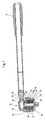
- FIG. 1 shows a torque wrench 14 according to the invention for controlled twisting of rotatable elements such as screws, nuts and the like with a tool head 10 and one with the tool head 10 rotatably connected handle 12 via a shaft, the Tool head 10 means 16 for transmitting a torque from the Tool head 10 on a rotatably mounted relative to the tool head 10 Has tool holder 18.
- the means 16 consist of a exclusively friction clutch.
- the frictional Clutch 16 is designed as an elastic element 20, 22 Diaphragm spring arrangement can be preloaded.
- the value for the torque transmitted through the clutch 16 is adjustable.
- the clutch 16 is a multi-plate clutch and the lamellae 26 of a first group, which rotate with the tool head 10 are connected, alternate with slats 24 of a second group, which are non-rotatably connected to the tool holder 18.
- the tool head 10 has a sleeve 28, through which the Disc spring arrangement 20, 22 acting on the clutch 16 force a pressure plate 46 is adjustable.
- a marking 30 on the sleeve 28 provided by which the limit value of the transmissible torque can be displayed (Fig. 2).
- the sleeve 28 has an opening 34 for Attach a setting element, not shown.
- the sleeve 28 is provided with an internal thread 36 into which an external thread 42 a the clutch 16 receiving housing 38 can be screwed. about a not shown locking device, the housing 38 against unintentional rotation relative to the sleeve 28 can be secured.
- the multi-plate clutch 16 In the space formed by the housing 38 screwed into the sleeve 28 are the multi-plate clutch 16, the pressure plate 46 and the plate spring arrangement 20, 22 axially arranged in this order.
- the sleeve 28 By turning the sleeve 28 compared to the housing 38 changes due to the screw connection 36, 42 the axial extent of the space formed, whereby the Disc spring assembly 20, 22 is biased accordingly.
- This Bias is applied to the multi-plate clutch 16 via the pressure plate 46 transmitted, whereby the switching torque can be specified.
- a ratchet unit 44 is arranged in the tool head 10, which with the tool holder 16 cooperates so that in an adjustable Direction of rotation of a freewheel of the tool holder 18 relative to the Tool head 10 and in the opposite direction of rotation Take-away is reachable.
- the torque wrench 14 can be used as an ordinary reversible ratchet be, in addition to an ordinary ratchet maximum torque is adjustable with which the fasteners get dressed by.
- the use of the Multi-plate clutch 16 has the advantage that sliding friction between the Slats can be set relatively high after switching, so that especially when used manually due to the dynamic movement does not lead to slipping at a high rotational speed, which could injure the user, for example by using the Handle hits a stop.
Landscapes
- Engineering & Computer Science (AREA)
- Mechanical Engineering (AREA)
- Details Of Spanners, Wrenches, And Screw Drivers And Accessories (AREA)
Applications Claiming Priority (2)
| Application Number | Priority Date | Filing Date | Title |
|---|---|---|---|
| DE20114707U | 2001-09-06 | ||
| DE20114707U DE20114707U1 (de) | 2001-09-06 | 2001-09-06 | Drehmomentwerkzeug |
Publications (2)
| Publication Number | Publication Date |
|---|---|
| EP1297929A2 true EP1297929A2 (fr) | 2003-04-02 |
| EP1297929A3 EP1297929A3 (fr) | 2005-03-23 |
Family
ID=7961387
Family Applications (1)
| Application Number | Title | Priority Date | Filing Date |
|---|---|---|---|
| EP02014588A Withdrawn EP1297929A3 (fr) | 2001-09-06 | 2002-07-02 | Clé dynamométrique avec embrayage à liaison friction |
Country Status (2)
| Country | Link |
|---|---|
| EP (1) | EP1297929A3 (fr) |
| DE (1) | DE20114707U1 (fr) |
Cited By (1)
| Publication number | Priority date | Publication date | Assignee | Title |
|---|---|---|---|---|
| CN100410022C (zh) * | 2005-09-28 | 2008-08-13 | 胡厚飞 | 可调整扭力的微小扭力工具 |
Families Citing this family (1)
| Publication number | Priority date | Publication date | Assignee | Title |
|---|---|---|---|---|
| DE102010033277A1 (de) | 2010-07-07 | 2012-01-12 | Nc-Automation Gmbh | Drehmomentschraubwerkzeug für CNC-Werkzeugmaschinen |
Family Cites Families (5)
| Publication number | Priority date | Publication date | Assignee | Title |
|---|---|---|---|---|
| DE691051C (de) * | 1938-04-08 | 1940-05-15 | Karl Wolfram | Drehmomentschraubeneinzieh- und Kontrollwerkzeug |
| DE703205C (de) * | 1939-07-16 | 1941-03-04 | Hans Joachim Schroeder Dr Ing | Einrichtung, vorzugsweise an Schraubenschluesseln, zum genauen Begrenzen eines zwischen zwei Reibflaechen uebertragenen Drehmoments |
| US2525379A (en) * | 1946-08-03 | 1950-10-10 | Airdraulics Engineering Inc | Torque tool |
| US2831383A (en) * | 1956-10-05 | 1958-04-22 | Hanley L Riess | Predetermined torque release hand tool |
| DE2549153C3 (de) * | 1975-11-03 | 1978-12-21 | Altenloh, Brinck & Co, 5828 Ennepetal | Vorsatzgerät für Handbohrmaschinen zum Eindrehen von Schrauben |
-
2001
- 2001-09-06 DE DE20114707U patent/DE20114707U1/de not_active Expired - Lifetime
-
2002
- 2002-07-02 EP EP02014588A patent/EP1297929A3/fr not_active Withdrawn
Cited By (1)
| Publication number | Priority date | Publication date | Assignee | Title |
|---|---|---|---|---|
| CN100410022C (zh) * | 2005-09-28 | 2008-08-13 | 胡厚飞 | 可调整扭力的微小扭力工具 |
Also Published As
| Publication number | Publication date |
|---|---|
| DE20114707U1 (de) | 2001-10-31 |
| EP1297929A3 (fr) | 2005-03-23 |
Similar Documents
| Publication | Publication Date | Title |
|---|---|---|
| EP0178252B1 (fr) | Outil de vissage motorisé | |
| DE102010062014B3 (de) | Handwerkzeugmaschine | |
| DE3023005C2 (de) | Drehschrauber mit Drehmomentbegrenzungseinrichtung | |
| EP3324860B1 (fr) | Cliquet à roue libre à encombrement réduit | |
| EP0699508B1 (fr) | Visseuse à percussion hydraulique notamment pour le serrage de connections filetées | |
| DE102019111185A1 (de) | Spannvorrichtung für eine Schraubverbindung | |
| DE10161356B4 (de) | Schraubgerät | |
| DE2805881C2 (de) | Spanndorn für die koaxiale Außenbearbeitung von Werkstücken mit Innenverzahnung | |
| EP1297929A2 (fr) | Clé dynamométrique avec embrayage à liaison friction | |
| EP4380755A1 (fr) | Clé à chocs ou à impulsions et procédé de vissage de vis | |
| EP0174276A1 (fr) | Outil de serrage à moteur | |
| DE2731090A1 (de) | Drehmoment-schrauber | |
| DE102004028981B4 (de) | Drehmomentverstellbares Werkzeug | |
| DE29618817U1 (de) | Drehmomentverstärkender Schrauber | |
| DE2650424A1 (de) | Drehmomentuebertragungs- und anzeige-vorrichtung | |
| DE2520250A1 (de) | Abstuetzvorrichtung fuer getriebeschraubenschluessel | |
| DE19819251B4 (de) | Handnietgerät zum Setzen von Blindnietmuttern | |
| DE102017004043A1 (de) | Drehmomentschlüssel mit vordefinierter Drehmomentbegrenzung | |
| EP0929380A1 (fr) | Tourne-vis amplificateur de couple | |
| DE202006006273U1 (de) | Schraubgerät | |
| DE2348299A1 (de) | Spannfutter fuer schlagende und/oder bohrende elektrowerkzeuge | |
| DE3306809C1 (de) | Bohrgeraete | |
| DE1938338C3 (de) | Vorrichtung zum maschinellen Ein- und Ausdrehen von Schienenbefestigungsschrauben | |
| DE3639098A1 (de) | Druckluftschrauber | |
| DE3032733A1 (de) | Drehmomentschuessel |
Legal Events
| Date | Code | Title | Description |
|---|---|---|---|
| PUAI | Public reference made under article 153(3) epc to a published international application that has entered the european phase |
Free format text: ORIGINAL CODE: 0009012 |
|
| AK | Designated contracting states |
Kind code of ref document: A2 Designated state(s): AT BE BG CH CY CZ DE DK EE ES FI FR GB GR IE IT LI LU MC NL PT SE SK TR Designated state(s): AT BE BG CH CY CZ DE DK EE ES FI FR GB GR IE IT LI LU MC NL PT SE SK TR |
|
| AX | Request for extension of the european patent |
Extension state: AL LT LV MK RO SI |
|
| PUAL | Search report despatched |
Free format text: ORIGINAL CODE: 0009013 |
|
| AK | Designated contracting states |
Kind code of ref document: A3 Designated state(s): AT BE BG CH CY CZ DE DK EE ES FI FR GB GR IE IT LI LU MC NL PT SE SK TR |
|
| AX | Request for extension of the european patent |
Extension state: AL LT LV MK RO SI |
|
| AKX | Designation fees paid |
Designated state(s): AT BE BG CH CY CZ DE DK EE ES FI FR GB GR IE IT LI LU MC NL PT SE SK TR |
|
| STAA | Information on the status of an ep patent application or granted ep patent |
Free format text: STATUS: THE APPLICATION IS DEEMED TO BE WITHDRAWN |
|
| 18D | Application deemed to be withdrawn |
Effective date: 20050924 |