EP1299204B1 - Procede et dispositif de coulee ascendante a l'aide d'un moule pourvu d'un orifice de coulee place vers le bas et dote d'une fermeture coulissante - Google Patents
Procede et dispositif de coulee ascendante a l'aide d'un moule pourvu d'un orifice de coulee place vers le bas et dote d'une fermeture coulissante Download PDFInfo
- Publication number
- EP1299204B1 EP1299204B1 EP01969359A EP01969359A EP1299204B1 EP 1299204 B1 EP1299204 B1 EP 1299204B1 EP 01969359 A EP01969359 A EP 01969359A EP 01969359 A EP01969359 A EP 01969359A EP 1299204 B1 EP1299204 B1 EP 1299204B1
- Authority
- EP
- European Patent Office
- Prior art keywords
- opening
- casting
- riser pipe
- flow
- mould
- Prior art date
- Legal status (The legal status is an assumption and is not a legal conclusion. Google has not performed a legal analysis and makes no representation as to the accuracy of the status listed.)
- Expired - Lifetime
Links
- 238000005266 casting Methods 0.000 title claims abstract description 83
- 238000000034 method Methods 0.000 title claims abstract description 22
- 239000007788 liquid Substances 0.000 claims abstract description 8
- 239000000155 melt Substances 0.000 claims description 15
- 229910001092 metal group alloy Inorganic materials 0.000 claims description 3
- 239000000919 ceramic Substances 0.000 claims description 2
- 238000006073 displacement reaction Methods 0.000 claims 2
- 230000001681 protective effect Effects 0.000 claims 1
- 230000006835 compression Effects 0.000 description 7
- 238000007906 compression Methods 0.000 description 7
- 230000000630 rising effect Effects 0.000 description 5
- 238000007711 solidification Methods 0.000 description 4
- 230000008023 solidification Effects 0.000 description 4
- 230000002349 favourable effect Effects 0.000 description 2
- 230000003647 oxidation Effects 0.000 description 2
- 238000007254 oxidation reaction Methods 0.000 description 2
- 239000011819 refractory material Substances 0.000 description 2
- 238000007789 sealing Methods 0.000 description 2
- 239000007787 solid Substances 0.000 description 2
- 230000000712 assembly Effects 0.000 description 1
- 238000000429 assembly Methods 0.000 description 1
- 238000010276 construction Methods 0.000 description 1
- 230000001419 dependent effect Effects 0.000 description 1
- 230000000994 depressogenic effect Effects 0.000 description 1
- 239000007789 gas Substances 0.000 description 1
- 230000005484 gravity Effects 0.000 description 1
- 239000011261 inert gas Substances 0.000 description 1
- 238000004519 manufacturing process Methods 0.000 description 1
- 239000000463 material Substances 0.000 description 1
- 239000007769 metal material Substances 0.000 description 1
- 239000012778 molding material Substances 0.000 description 1
- 238000003032 molecular docking Methods 0.000 description 1
- 238000007493 shaping process Methods 0.000 description 1
Images
Classifications
-
- B—PERFORMING OPERATIONS; TRANSPORTING
- B22—CASTING; POWDER METALLURGY
- B22D—CASTING OF METALS; CASTING OF OTHER SUBSTANCES BY THE SAME PROCESSES OR DEVICES
- B22D18/00—Pressure casting; Vacuum casting
- B22D18/04—Low pressure casting, i.e. making use of pressures up to a few bars to fill the mould
Definitions
- the invention relates to a method and a device for rising casting / low pressure casting - especially of light metal alloys - with a bottom casting furnace with a Riser and a mouth of the riser and with a mold with bottom pouring and with a Slider closure for the sprue, which has a passageway which forms a substantially straightforward for pouring Longitudinal course in particular a constant cross-section accepts.
- the rising watering has the Significant advantage of a controlled controlled casting process. This will cause the air bubble entry and the oxidation skin entry, the with every swirling of the melt during casting goes along with it.
- core packages as Casting can here the detachment and entrainment of molding material be avoided in the gate and in the run, the otherwise to Reduction of the quality of the castings leads.
- a disadvantage of rising casting it is generally that the Solidification process of up to 15 min duration to be awaited must be removed before the currently filled mold and the next Casting mold can be brought over the casting furnace.
- the Solidification process of up to 15 min duration to be awaited must be removed before the currently filled mold and the next Casting mold can be brought over the casting furnace.
- the solution lies in a method for increasing casting / low-pressure casting, in which to shut off in the slide closure two immediately adjoining opening sections of the Passage channel immediately after pouring at still liquid Melt in the sprue transverse to the longitudinal course of Passage channel are shifted against each other so that a overhead opening section with the sprue opening undercut-free remains open and a bottom one Opening section with the mouth of the riser open remains connected, with the opening portions completely against each other are offset, and then the melt in the Riser lowered to below the mouth of the riser is, wherein the lower opening portion of the passage channel emptied of melt.
- a corresponding inventive Device is characterized in that the slide closure comprises two mutually displaceable plates, the each having a passage opening, wherein the plates for Casting can be brought into overlap with their passage openings are and the plates to shut off so mutually displaceable are that the passage opening in the upper plate with the Gutter opening is connected undercut open and the Passage opening in the lower plate with the riser open is connected while the passages completely offset from each other.
- the mutually displaceable plates can be in a linear Movement or in a rotating motion relative to each other to be moved.
- the method is carried out in such a way that the melt in the riser after closing the Slider closure only slightly below the mouth opening of the riser is lowered to allow access of air to reduce a minimum. It is particularly favorable here, the Riser tube when slightly lowering the melt between the To apply to individual casting operations with inert gas, so that the oxidation is reduced at the melt level in the riser.
- the mold behaves the riser when placing the mold with the part forming the mouth opening elastically yielding, the mold is placed on the riser that a defined Pad pressure between the slide closure and the mouth opening forming part of the riser. This can e.g. be made that when placing the mold this after a slight elastic yielding of the riser is caught by the casting table.
- the mold can also be used in Guides are introduced across the casting table so that in the pouring position the riser a slightly depressed Position taken. Finally, when stuck on the Casting table spanned casting mold of the casting furnace with the riser until the construction of the desired contact pressure to the slide closure be moved up.
- the riser the casting table in an opening interspersed and the mouth of the riser a little above the level of the casting table, the only for Placing the mold is used while riser and slide closure directly in contact with each other.
- the upper plate slidable and the lower plate is fixed, wherein the pouring opening of the mold is larger is, as the passage opening in the upper plate, so that they the passage opening in the upper plate in the two Positions covered.
- the top plate it is possible for the top plate to be fixed and the lower plate is slidable and the mouth opening of the riser is greater than the passage opening in the lower plate, so that it has the passage opening in the lower Plate covered in its two positions. In both cases Two-plate pushers are formed. Over the top plate can on the mold side also another in the context of the slider closure held base plate lie, the passage opening must correspond to the pouring opening of the mold.
- connection plate with the mouth of the riser and the thus firmly connected Riser at one end of an elastic corrugated tube are fixed, and one firmly connected to the casting furnace Base flange with the other end of the elastic corrugated tube connected is. If a mold is lowered onto the riser, So this corrugated tube height and angle error of the connection level compensate the mold.
- the riser carries at the upper end a connecting flange, on which a ceramic connecting plate is held, which forms directly the mouth of the riser.
- the mouth opening is a slot and that the mouth opening widens downwards within the connection plate with small opening angles ( ⁇ 3 , ⁇ 4 ).
- the backflow of the melt from the slide closure after shut-off is facilitated by the fact that the passage opening in the lower plate with a low opening angle ( ⁇ 2 ) widens downwards.
- the passage opening in the upper plate with a small opening angle ( ⁇ 1 ) widens upwards.
- the casting mold may be a permanent casting mold or, in particular, a be a core pack clamped in a mold frame.
- a slide lock can be fixed be arranged while an actuator for the Slide lock fixed to the casting table on which the mold can be discontinued, may be appropriate.
- each slider closure has an integrated actuator exhibit.
- the first to method refers and devices in which the melt level in the sealed casting furnace a controllable gas pressure is given up, the melt in the riser rise or fall back.
- a controllable gas pressure is given up, the melt in the riser rise or fall back.
- other methods and devices which promote the melt in the riser controllable can, e.g. Magnetic pump assemblies at the bottom of the riser in the casting furnace.
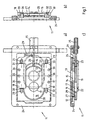
- a slide closure 11 which has a Base frame 24 includes the bottom of a permanent mold / a Mold frame for a core package can be screwed. Of the Base frame 24 holds a base plate 29 via a wedge element 12 in sealing engagement with a Befest Trentsiguns Colour the permanent mold / the Mold frame (not shown here).
- the base plate 12 has a passage opening 13 which with a Pouring the mold frame are brought into coincidence can.
- On the base plate 12 is a first fixed Slide plate 14 with an upper passage opening 15; the first slide plate 14 is partially in the base plate 12th let in and held in a frame 27.
- the frame 27 serves for tension-free setting of the refractory material existing first slide plate 14.
- the passage opening 15th the fixed first slide plate 14 is located with the Passage opening 13 in the base plate 12 in coverage.
- the Openings 13, 15 are in the direction of the above assumed Mold undercut free.
- Under the first slide plate 14 a second slide plate 16 is arranged, which is a lower Passage opening 17 has.
- the slide plate 16 is in planar sealing system with the first slide plate 14 and in a frame 28 clamped.
- the frame 28 serves for low tension Clamping the second made of fiery material Slide plate 16.
- the two slide plates 14, 16 are by resilient holding means against each other and together against the Base plate 12 pressed.
- the holding means are immediately on the base plate 12 and comprise two support rails 18, 19, in attached to the base plate 12 pairs of tabs 20, 21, 22, 23 pivotally mounted in pivots 30, 31, 32, 33 are.
- the second slide plate 16 is connected by a rod 26 manipulatable, which attacks on the frame 28 and in one on the Base frame 24 patch guide piece 25 slides.
- the mentioned Retaining rails 18, 19 are supported by three each Compression springs 34, 35, 36, 37, 38, 39 on the base plate 12 from and As two-armed levers, they act directly on the second one Slider plate 16.
- the above-mentioned openings 13, 15, 17 in the base plate 12 and in the slide plates 14, 16 are each circular.
- Position is the lower slide plate 16 opposite the upper Slide plate 15 shifted so that the passages 15, 17 are completely offset from each other, i. the slide lock is in its closed position.
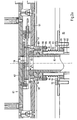
- FIG 2 the upper end of a cast furnace 81 (only Figure 2a) and also an overlying casting table 51 and a casting table placed on the mold frame 61 is shown in their mutual assignment for a casting.
- the casting furnace 81 has an upper opening 82, in which a riser 83 is inserted with the interposition of an elastic corrugated tube 84.
- the corrugated tube 84 has for connection to the casting furnace 81 and the riser 83 two connecting flanges 85, 86, which are sealed by seals 87, 88 opposite the casting furnace 81 and a riser pipe flange 89 attached to the riser.
- the lower connecting flange 85 is clamped by means of holding clamps 90, 91, by screws 92, 93 with the casting furnace 81.
- the upper Anschußflansch 86 is bolted by screws 94, 95 directly to the Steigrohrflansch 89. Further screw connections are not quantified in detail.
- a retaining ring 96 is placed, which in turn carries a clamping ring 97.
- the clamping ring holds an abutment plate 98 with a mouth 99.
- the mouth opening 99 is elongated and about twice as long as width.
- the last mentioned the upper end of the riser forming parts pass through the casting table 51 in a circular opening 52.
- catching pins 53, 54 are used, on which catch mouths 57, 58 of the mold frame 61 catch.
- the mold frame 61 has a base plate 62 with a pouring port 79 into which a sleeve 80 of refractory material is inserted. Below is screwed to the base plate 62, a slide closure 11 according to Figure 1, wherein the sleeve 80 is at the same time fitted into the passage opening 13 of the base plate 12.
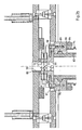
- ⁇ 1 which, as already mentioned, opens upwards.
- At the passage opening 15 closes down the passage opening 17 of the lower slide plate 16 with an opening angle ⁇ 2 , which opens down, as well as the mouth opening 99 in the connection plate 98, the corresponding inner bevel angle ⁇ 3 , ⁇ 4 .
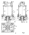
- the mold frame 61 is recognizable as a whole; however the casting furnace 81 and the upper end of the riser 83 are simplified compared with Figure 2 shown. In particular, that is Corrugated tube 84 reproduced only symbolically with the flanges.
- the mold frame 61 consists of the base plate 62, a Cover plate 67 and tie rods 63, 64, 65, 66. Above the cover plate 67 is a support plate 68, at the two eyelets 69, 70th are bolted, which via bolts 71, 72, 73, 74 and sleeves 75, 76, 77, 78 are screwed to the cover plate 63.
- the lower Screws of the clamping rods 64, 65, 66 are not closer protected sockets protected.
- the casting table 51 catch 53, 54, 55 recognizable, on which the Fangmäuler 57, 58, 59, 60 of the mold frame 61 have caught.
- the Mold frame 61 comprises a base plate 62, at the bottom of the slide closure 11 is screwed according to FIG.
- the corrugated tube 84 yield elastically to a completely flat Plant the contact plate 98 on the lower slide plate 16 of the Ensure slide closure 11.
- the proportions the orifice 99 in the connection plate 98 and the passage opening 17 in the lower slide plate 16 are such that both in the open position and in the closed position of Slider closure the passage opening 17 of the slide plate 16 open with the mouth opening 99 of the connection plate 98th of the riser 83 remains connected. This leaves a backflow of melt from the passage opening 17 in the riser after closing the slide closure 11 possible.
Landscapes
- Engineering & Computer Science (AREA)
- Mechanical Engineering (AREA)
- Molds, Cores, And Manufacturing Methods Thereof (AREA)
- Casting Support Devices, Ladles, And Melt Control Thereby (AREA)
- Sliding Valves (AREA)
- Barrages (AREA)
- Refuge Islands, Traffic Blockers, Or Guard Fence (AREA)
- Investigation Of Foundation Soil And Reinforcement Of Foundation Soil By Compacting Or Drainage (AREA)
- Casting Devices For Molds (AREA)
Claims (15)
- Procédé de coulée ascendante/coulée basse pression - en particulier d'alliages de métaux légers -avec un four de fusion situé sous une table à couler, avec un jet de coulée et une embouchure de jet de coulée, etavec un moule avec un orifice de coulée placé vers le bas, etavec une fermeture coulissante, qui forme un chenal de passage, qui adopte pour la coulée, un tracé longitudinal essentiellement droit,dans lequel pour l'obturation de la fermeture coulissante, deux segments d'ouverture se raccordant directement l'un à l'autre, du chenal de passage, sont fermés l'un par rapport à l'autre directement après la coulée alors que la masse fondue est encore liquide dans l'orifice de coulée, transversalement au tracé longitudinal du chenal de passage, de sorte qu'un segment d'ouverture placé vers le haut reste en liaison d'ouverture, sans rainure arrière, avec l'orifice de coulée et qu'un segment d'ouverture placé vers le bas reste en liaison d'ouverture avec l'embouchure du jet de coulée , où les segments d'ouverture se trouvent complètement désaxés l'un par rapport à l'autre,dans lequel ensuite, la masse fondue est descendue dans le jet de coulée jusqu'à sous l'embouchure du jet de coulée, où le segment d'ouverture inférieur du chenal de passage se vide de la masse fondue, etdans lequel le moule est mis sur le jet de coulée de sorte que s'ajuste une pression d'appui définie entre la fermeture coulissante et la partie formant embouchure du jet de coulée, en ce que lors de la mise du moule sur le jet de coulée, celui-ci se comporte de manière souple et élastique sur la partie formant embouchure.
- Procédé selon la revendication 1, caractérisé en ce que la masse fondue est descendue dans le jet de coulée seulement faiblement sous l'embouchure du jet de coulée, après la fermeture du segment d'ouverture du canal de passage par rapport à la fermeture coulissante.
- Procédé selon l'une des revendications 1 et 2, caractérisé en ce que le jet de coulée réceptionne un verre de protection sur l'embouchure lors de la descente de la masse fondue, après la fermeture du segment d'ouverture du chenal de passage.
- Procédé selon l'une des revendications 1 à 3, caractérisé en ce qu'après la descente de la masse fondue dans le jet de coulée, le moule avec la fermeture coulissante, dont le segment d'ouverture inférieur du chenal de passage est vidé de la masse fondue, est séparé de l'embouchure du jet de coulée.
- Dispositif de coulée ascendante/coulée basse pression - en particulier d'alliages de métaux légers -avec un four de fusion (81) situé sous un moule à table (51) avec un jet de coulée (83) et une embouchure (99) de jet de coulée (83), etavec un moule avec un orifice de coulée placé vers le bas (79), etavec une fermeture coulissante (11) mise sur le moule pour l'orifice de coulée (79), qui forme un chenal de passage, qui adopte pour la coulée, un tracé longitudinal essentiellement droit,où la fermeture coulissante (11) comprend deux plaques mobiles l'une par rapport à l'autre (14, 16), qui présentent chaque fois, une ouverture de passage (15, 17), où les plaques (14, 16) peuvent être amenées en superposition avec leur ouverture de passage (15, 17) pour la coulée de sorte que l'ouverture de sortie (15) de la plaque supérieure (14) est en liaison d'ouverture avec l'ouverture d'entrée (79), sans rainure arrière, et l'ouverture de passage (17) dans la plaque inférieure (16) est en liaison d'ouverture avec l'embouchure (99) du jet de coulée (83), pendant que les ouvertures de passage (15, 17) sont complètement désaxées l'une par rapport à l'autre,où le jet de coulée (83) est formé de manière souple et élastique, de sorte que s'ajuste une pression d'appui définie entre la fermeture coulissante et la partie formant embouchure du jet de coulée, après la pose du moule.
- Dispositif selon la revendication 5, caractérisé en ce que la plaque supérieure (14) est mobile et la plaque inférieure (16) est fixe, où l'orifice de coulée (79) du moule est plus grand que l'orifice de passage (15) dans la plaque supérieure (14), de sorte qu'il couvre l'ouverture de passage (15) dans la plaque supérieure (14) dans les deux positions.
- Dispositif selon la revendication 5, caractérisé en ce que la plaque supérieure (14) est fixe et la plaque inférieure (16) est mobile, et l'embouchure (99) du jet de coulée est plus grande que l'orifice de passage (17) dans la plaque inférieure (16), de sorte qu'il couvre l'ouverture de passage (17) dans la plaque inférieure (16) dans les deux positions.
- Dispositif selon l'une quelconque des revendications 5 à 7, caractérisé en ce que l'extrémité supérieure du jet de coulée (83) est reliée de manière élastique, par un tube ondulé (84) entourant celle=ci de manière coaxiale, à une ouverture de sortie (82) pour le jet de coulée (83) dans le moule (81).
- Dispositif selon la revendication 8, caractérisé en ce que le tube ondulé porte sur les deux extrémités, deux bourrelets de raccordement (85, 86).
- Dispositif selon l'une quelconque des revendications 8 et 9, caractérisé en ce que le jet de coulée (83) porte sur l'extrémité supérieure, un bourrelet de raccordement (96), sur lequel est maintenu une plaque de raccordement en céramique, qui forme directement, l'embouchure (99) du jet de coulée.
- Dispositif selon la revendication 10, caractérisé en ce que l'embouchure (99) est un orifice longitudinal et en ce que l'embouchure (99) s'élargit vers le bas avec un angle d'ouverture faible (α3, α4) dans les plaques de raccordement (98).
- Dispositif selon l'une quelconque des revendications 5 à 11, caractérisé en ce que l'ouverture de passage (17) s'élargit vers le bas dans la plaque inférieure (16) avec un angle d'ouverture faible (α2).
- Dispositif selon l'une quelconque des revendications 5 à 12, caractérisé en ce que l'ouverture de passage (15) s'élargit vers le haut dans la plaque supérieure (14) avec un angle d'ouverture faible (α1).
- Dispositif selon l'une quelconque des revendications 5 à 13, caractérisé en ce que le moule est formé d'un moule permanent ou d'un empilage de tôles de noyau pressées dans un cadre (61)
- Dispositif selon la revendication 14, caractérisé en ce que la fermeture coulissante (11) est reliée fermement au moule permanent ou au cadre (61).
Priority Applications (3)
| Application Number | Priority Date | Filing Date | Title |
|---|---|---|---|
| SI200130352T SI1299204T1 (en) | 2000-07-12 | 2001-07-10 | Method and device for uphill casting/low pressure casting having a mould with anunderlying pouring-in opening and having a slide valve closure |
| DK01969359T DK1299204T3 (da) | 2000-07-12 | 2001-07-10 | Fremgangsmåde og indretning til stigende stöbning med en stöbeform med bundplaceret indstöbningsåbning med et skydespjæld |
| DE20122418U DE20122418U1 (de) | 2000-07-12 | 2001-07-10 | Vorrichtung zum steigenden Gießen mit einer Gießform mit untenliegender Eingußöffnung mit einem Schieberverschluß |
Applications Claiming Priority (3)
| Application Number | Priority Date | Filing Date | Title |
|---|---|---|---|
| DE10033903A DE10033903C1 (de) | 2000-07-12 | 2000-07-12 | Verfahren und Vorrichtung zum steigenden Giessen mit einer Giessform mit untenliegender Eingussöffnung mit einem Schieberverschluss |
| DE10033903 | 2000-07-12 | ||
| PCT/EP2001/007916 WO2002004144A2 (fr) | 2000-07-12 | 2001-07-10 | Procede et dispositif de coulee ascendante a l'aide d'un moule pourvu d'un orifice de coulee place vers le bas et dote d'une fermeture coulissante |
Publications (2)
| Publication Number | Publication Date |
|---|---|
| EP1299204A2 EP1299204A2 (fr) | 2003-04-09 |
| EP1299204B1 true EP1299204B1 (fr) | 2005-03-23 |
Family
ID=7648699
Family Applications (1)
| Application Number | Title | Priority Date | Filing Date |
|---|---|---|---|
| EP01969359A Expired - Lifetime EP1299204B1 (fr) | 2000-07-12 | 2001-07-10 | Procede et dispositif de coulee ascendante a l'aide d'un moule pourvu d'un orifice de coulee place vers le bas et dote d'une fermeture coulissante |
Country Status (13)
| Country | Link |
|---|---|
| US (1) | US6899159B2 (fr) |
| EP (1) | EP1299204B1 (fr) |
| AT (1) | ATE291514T1 (fr) |
| AU (2) | AU8963601A (fr) |
| BR (1) | BR0112410A (fr) |
| CA (1) | CA2414770A1 (fr) |
| DE (2) | DE10033903C1 (fr) |
| ES (1) | ES2240515T3 (fr) |
| HU (1) | HUP0301599A2 (fr) |
| MX (1) | MXPA03000285A (fr) |
| PL (1) | PL199011B1 (fr) |
| SK (1) | SK286624B6 (fr) |
| WO (1) | WO2002004144A2 (fr) |
Families Citing this family (5)
| Publication number | Priority date | Publication date | Assignee | Title |
|---|---|---|---|---|
| DE10033903C1 (de) * | 2000-07-12 | 2001-11-29 | Vaw Ver Aluminium Werke Ag | Verfahren und Vorrichtung zum steigenden Giessen mit einer Giessform mit untenliegender Eingussöffnung mit einem Schieberverschluss |
| EP1631406B1 (fr) * | 2003-06-14 | 2007-04-11 | Stopinc Aktiengesellschaft | Poste de coulee, notamment pour la coulee du metal sous pression |
| DE102004016574A1 (de) * | 2004-03-31 | 2005-10-27 | Georg Fischer Kokillenguss GmbH | Kokillengiessanlage |
| DE102004043444B3 (de) * | 2004-09-06 | 2006-06-14 | Hydro Aluminium Alucast Gmbh | Verfahren und Vorrichtung zum Gießen von Metallschmelze |
| KR101517571B1 (ko) * | 2014-06-26 | 2015-05-06 | 고동근 | 진공환경에서 금속을 용해하고 성형하는 장치 및 방법 |
Family Cites Families (16)
| Publication number | Priority date | Publication date | Assignee | Title |
|---|---|---|---|---|
| CH415972A (de) * | 1964-03-06 | 1966-06-30 | Alusuisse | Druckgiessverfahren und Einrichtung zur Durchführung des Verfahrens |
| FR1525455A (fr) * | 1965-11-02 | 1968-05-17 | Babcock & Wilcox Co | Tubes de coulée sous pression |
| GB1155427A (en) * | 1965-11-02 | 1969-06-18 | Babcock & Wilcox Co | Refractory Pouring Tubes |
| US3627018A (en) * | 1969-09-23 | 1971-12-14 | Amsted Ind Inc | Method for producing castings in a permanent mold |
| US3905419A (en) * | 1970-09-29 | 1975-09-16 | Gravicast Patent Gmbh | Device for rise casting into a mold |
| AT317460B (de) * | 1970-09-29 | 1974-08-26 | Gravicast Patent Gmbh | Vorrichtung zum Gießen im steigenden Guß oder Mittelguß und Verfahren zur Herstellung einer Gußform zur Verwendung in dieser Vorrichtung |
| FR2270037B1 (fr) * | 1974-05-10 | 1979-04-06 | Pechiney Aluminium | |
| JPS5527495A (en) * | 1978-08-19 | 1980-02-27 | Stopinc Ag | Threeeply system sliding closing appliance |
| JPH07115151B2 (ja) * | 1988-03-22 | 1995-12-13 | 本田技研工業株式会社 | 低圧鋳造方法及び低圧鋳造装置 |
| FR2663571B1 (fr) | 1990-06-22 | 1994-11-25 | Pont A Mousson | Procede, moule et installation de coulee de metal sous basse pression. |
| DE4304622C2 (de) * | 1993-02-16 | 1996-09-19 | Bruehl Aluminiumtechnik | Verfahren zum Füllen einer Gießform |
| DE19807623A1 (de) * | 1998-02-21 | 1999-08-26 | Georg Fischer Disa Ag | Niederdruck-Gießverfahren für Leichtmetalle, insbesondere Aluminium |
| DE19821419A1 (de) * | 1998-05-13 | 1999-11-18 | Georg Fischer Disa Ag | Verfahren zum steigenden Niederdruck-Gießen von Metall, insbesondere Leichtmetall |
| DE19821946A1 (de) * | 1998-05-15 | 1999-11-18 | Friedhelm Kahn | Verfahren und Vorrichtungen zum automatischen Gießen von Bauteilen durch quantifiziertes Füllen eines Raumes mit geschmolzenem Metall |
| DE10033903C1 (de) * | 2000-07-12 | 2001-11-29 | Vaw Ver Aluminium Werke Ag | Verfahren und Vorrichtung zum steigenden Giessen mit einer Giessform mit untenliegender Eingussöffnung mit einem Schieberverschluss |
| DE10033904A1 (de) * | 2000-07-12 | 2002-01-31 | Stopinc Ag Huenenberg | Schieberverschluss zum Vergiessen von Metallschmelze, sowie eine dazugehörige feuerfeste Platteneinheit |
-
2000
- 2000-07-12 DE DE10033903A patent/DE10033903C1/de not_active Expired - Fee Related
-
2001
- 2001-07-10 WO PCT/EP2001/007916 patent/WO2002004144A2/fr not_active Ceased
- 2001-07-10 CA CA002414770A patent/CA2414770A1/fr not_active Abandoned
- 2001-07-10 AU AU8963601A patent/AU8963601A/xx active Pending
- 2001-07-10 BR BR0112410-2A patent/BR0112410A/pt not_active Application Discontinuation
- 2001-07-10 SK SK24-2003A patent/SK286624B6/sk not_active IP Right Cessation
- 2001-07-10 ES ES01969359T patent/ES2240515T3/es not_active Expired - Lifetime
- 2001-07-10 US US10/332,588 patent/US6899159B2/en not_active Expired - Lifetime
- 2001-07-10 AU AU2001289636A patent/AU2001289636B2/en not_active Ceased
- 2001-07-10 PL PL359759A patent/PL199011B1/pl unknown
- 2001-07-10 EP EP01969359A patent/EP1299204B1/fr not_active Expired - Lifetime
- 2001-07-10 AT AT01969359T patent/ATE291514T1/de not_active IP Right Cessation
- 2001-07-10 MX MXPA03000285A patent/MXPA03000285A/es active IP Right Grant
- 2001-07-10 HU HU0301599A patent/HUP0301599A2/hu unknown
- 2001-07-10 DE DE50105702T patent/DE50105702D1/de not_active Expired - Lifetime
Also Published As
| Publication number | Publication date |
|---|---|
| SK242003A3 (en) | 2003-10-07 |
| BR0112410A (pt) | 2003-05-27 |
| MXPA03000285A (es) | 2005-04-19 |
| ES2240515T3 (es) | 2005-10-16 |
| PL359759A1 (en) | 2004-09-06 |
| ATE291514T1 (de) | 2005-04-15 |
| HUP0301599A2 (en) | 2003-08-28 |
| AU2001289636B2 (en) | 2004-11-04 |
| WO2002004144A2 (fr) | 2002-01-17 |
| WO2002004144A3 (fr) | 2002-06-20 |
| PL199011B1 (pl) | 2008-08-29 |
| DE10033903C1 (de) | 2001-11-29 |
| EP1299204A2 (fr) | 2003-04-09 |
| CA2414770A1 (fr) | 2002-01-17 |
| US6899159B2 (en) | 2005-05-31 |
| US20040011496A1 (en) | 2004-01-22 |
| WO2002004144A9 (fr) | 2002-09-19 |
| SK286624B6 (sk) | 2009-02-05 |
| AU8963601A (en) | 2002-01-21 |
| DE50105702D1 (de) | 2005-04-28 |
Similar Documents
| Publication | Publication Date | Title |
|---|---|---|
| EP0092686B1 (fr) | Dispositif de changement rapide et/ou serrage de moules pour machines à injection | |
| DE69508394T2 (de) | Verfahren zum schliessen des formeingusses einer nassgusform nach dem gegenschwerkraftgiessen einer nichteisenlegierung in einer stranggiessanlage | |
| DE102017108963B4 (de) | Verfahren und Vorrichtung zum Spritzgießen von Kunststoffen | |
| EP1122003A1 (fr) | Dispositif de fabrication d'une pièce moulée | |
| DE69126258T2 (de) | Schieberverschluss, verfahren zu dessen betrieb und auswechselbare feuerfestteile | |
| DE4022530C2 (de) | Düse für Spritzgießmaschinen | |
| DE10033903C1 (de) | Verfahren und Vorrichtung zum steigenden Giessen mit einer Giessform mit untenliegender Eingussöffnung mit einem Schieberverschluss | |
| EP1299203B1 (fr) | Procede et dispositif de coulee en source comportant une fermeture a tiroir placee sur le plateau de coulee | |
| EP1299201B1 (fr) | Fermeture a tiroir pour la coulee de bain de fusion | |
| DE2808324C3 (de) | Maschine zum Herstellen von Gießkernen | |
| EP1599328A1 (fr) | Procede de production d'articles moules par injection et buse a obturation a aiguille pour moule a injection | |
| EP0398389A2 (fr) | Tête et pulvérisation d'un dispositif de pulvérisation de liquide, en particulier d'un agent de séparation | |
| DE20122418U1 (de) | Vorrichtung zum steigenden Gießen mit einer Gießform mit untenliegender Eingußöffnung mit einem Schieberverschluß | |
| EP0937525A1 (fr) | Procédé pour la coulée de métaux légers à basse pression , en particulier de l'aluminium et dispositif pour la mise en oeuvre du procédé | |
| DE2233835B2 (de) | Anfahrstrang fuer eine stranggiessmaschine mit bogenfoermiger strangfuehrung | |
| DE2704322A1 (de) | Niederdruck-druckgussmaschine | |
| DE69127605T2 (de) | Senkrechter bodenschieber einer horizontal verschiebbaren form einer druckgussmaschine (vertikal) | |
| DE10151693C2 (de) | Komplettes Spritzseitenteil für eine Spritzgießmaschine und Verfahren zur Wartung des darin enthaltenen Heißkanal-Verteilersystems | |
| DE1421552B2 (de) | Vorrichtung zur Herstellung von Polbrücken für elektrische Akkumulatoren und zur gleichzeitigen Verschweißung der Polbrücken mit den Fahnen eines im Akkumulator befindlichen Plattensatzes | |
| DE4412082C2 (de) | Spritzgießwerkzeug | |
| DE2908210C2 (de) | Formmaschine, insbesondere Kernformmaschine | |
| DE10233962A1 (de) | Aktivspeisungsadapter | |
| DE3541659A1 (de) | Formeinrichtung zur herstellung von ringfoermig geschlossenen betonteilen, insbes. schachtringen, schachthaelsen oder dergl. | |
| WO2018192619A1 (fr) | Système à vanne de coupure, installation de fonderie et procédé de fonderie | |
| CH689447A5 (de) | Einrichtung zum Zufuehren einer Stahlschmelze in eine Stranggiesskokille. |
Legal Events
| Date | Code | Title | Description |
|---|---|---|---|
| PUAI | Public reference made under article 153(3) epc to a published international application that has entered the european phase |
Free format text: ORIGINAL CODE: 0009012 |
|
| 17P | Request for examination filed |
Effective date: 20021218 |
|
| AK | Designated contracting states |
Kind code of ref document: A2 Designated state(s): AT BE CH CY DE DK ES FI FR GB GR IE IT LI LU MC NL PT SE TR Designated state(s): AT BE CH CY DE DK ES FI FR GB GR IE IT LI LU MC NL PT SE TR |
|
| AX | Request for extension of the european patent |
Extension state: AL LT LV MK RO SI |
|
| RAP1 | Party data changed (applicant data changed or rights of an application transferred) |
Owner name: HYDRO ALUMINIUM DEUTSCHLAND GMBH |
|
| 17Q | First examination report despatched |
Effective date: 20031113 |
|
| GRAP | Despatch of communication of intention to grant a patent |
Free format text: ORIGINAL CODE: EPIDOSNIGR1 |
|
| GRAS | Grant fee paid |
Free format text: ORIGINAL CODE: EPIDOSNIGR3 |
|
| GRAA | (expected) grant |
Free format text: ORIGINAL CODE: 0009210 |
|
| RTI1 | Title (correction) |
Free format text: METHOD AND DEVICE FOR UPHILL CASTING/LOW PRESSURE CASTING HAVING A MOULD WITH ANUNDERLYING POURING-IN OPENING AND HAVING |
|
| AK | Designated contracting states |
Kind code of ref document: B1 Designated state(s): AT BE CH CY DE DK ES FI FR GB GR IE IT LI LU MC NL PT SE TR |
|
| AX | Request for extension of the european patent |
Extension state: RO SI |
|
| PG25 | Lapsed in a contracting state [announced via postgrant information from national office to epo] |
Ref country code: NL Free format text: LAPSE BECAUSE OF FAILURE TO SUBMIT A TRANSLATION OF THE DESCRIPTION OR TO PAY THE FEE WITHIN THE PRESCRIBED TIME-LIMIT Effective date: 20050323 Ref country code: FI Free format text: LAPSE BECAUSE OF FAILURE TO SUBMIT A TRANSLATION OF THE DESCRIPTION OR TO PAY THE FEE WITHIN THE PRESCRIBED TIME-LIMIT Effective date: 20050323 |
|
| REG | Reference to a national code |
Ref country code: GB Ref legal event code: FG4D Free format text: NOT ENGLISH |
|
| REG | Reference to a national code |
Ref country code: CH Ref legal event code: EP |
|
| REG | Reference to a national code |
Ref country code: IE Ref legal event code: FG4D Free format text: GERMAN |
|
| REF | Corresponds to: |
Ref document number: 50105702 Country of ref document: DE Date of ref document: 20050428 Kind code of ref document: P |
|
| PG25 | Lapsed in a contracting state [announced via postgrant information from national office to epo] |
Ref country code: GR Free format text: LAPSE BECAUSE OF FAILURE TO SUBMIT A TRANSLATION OF THE DESCRIPTION OR TO PAY THE FEE WITHIN THE PRESCRIBED TIME-LIMIT Effective date: 20050623 |
|
| REG | Reference to a national code |
Ref country code: SE Ref legal event code: TRGR |
|
| PG25 | Lapsed in a contracting state [announced via postgrant information from national office to epo] |
Ref country code: CY Free format text: LAPSE BECAUSE OF FAILURE TO SUBMIT A TRANSLATION OF THE DESCRIPTION OR TO PAY THE FEE WITHIN THE PRESCRIBED TIME-LIMIT Effective date: 20050710 Ref country code: LU Free format text: LAPSE BECAUSE OF NON-PAYMENT OF DUE FEES Effective date: 20050710 |
|
| PG25 | Lapsed in a contracting state [announced via postgrant information from national office to epo] |
Ref country code: CH Free format text: LAPSE BECAUSE OF NON-PAYMENT OF DUE FEES Effective date: 20050731 Ref country code: LI Free format text: LAPSE BECAUSE OF NON-PAYMENT OF DUE FEES Effective date: 20050731 Ref country code: MC Free format text: LAPSE BECAUSE OF NON-PAYMENT OF DUE FEES Effective date: 20050731 |
|
| REG | Reference to a national code |
Ref country code: DK Ref legal event code: T3 |
|
| GBT | Gb: translation of ep patent filed (gb section 77(6)(a)/1977) |
Effective date: 20050711 |
|
| NLV1 | Nl: lapsed or annulled due to failure to fulfill the requirements of art. 29p and 29m of the patents act | ||
| PG25 | Lapsed in a contracting state [announced via postgrant information from national office to epo] |
Ref country code: PT Free format text: LAPSE BECAUSE OF FAILURE TO SUBMIT A TRANSLATION OF THE DESCRIPTION OR TO PAY THE FEE WITHIN THE PRESCRIBED TIME-LIMIT Effective date: 20050907 |
|
| REG | Reference to a national code |
Ref country code: ES Ref legal event code: FG2A Ref document number: 2240515 Country of ref document: ES Kind code of ref document: T3 |
|
| PLBE | No opposition filed within time limit |
Free format text: ORIGINAL CODE: 0009261 |
|
| STAA | Information on the status of an ep patent application or granted ep patent |
Free format text: STATUS: NO OPPOSITION FILED WITHIN TIME LIMIT |
|
| 26N | No opposition filed |
Effective date: 20051227 |
|
| REG | Reference to a national code |
Ref country code: CH Ref legal event code: PL |
|
| ET | Fr: translation filed | ||
| PGFP | Annual fee paid to national office [announced via postgrant information from national office to epo] |
Ref country code: IE Payment date: 20060725 Year of fee payment: 6 |
|
| PGFP | Annual fee paid to national office [announced via postgrant information from national office to epo] |
Ref country code: BE Payment date: 20060822 Year of fee payment: 6 |
|
| PGFP | Annual fee paid to national office [announced via postgrant information from national office to epo] |
Ref country code: AT Payment date: 20070716 Year of fee payment: 7 |
|
| PGFP | Annual fee paid to national office [announced via postgrant information from national office to epo] |
Ref country code: GB Payment date: 20070720 Year of fee payment: 7 |
|
| BERE | Be: lapsed |
Owner name: *HYDRO ALUMINIUM DEUTSCHLAND G.M.B.H. Effective date: 20070731 |
|
| REG | Reference to a national code |
Ref country code: DK Ref legal event code: EBP |
|
| PGFP | Annual fee paid to national office [announced via postgrant information from national office to epo] |
Ref country code: SE Payment date: 20071115 Year of fee payment: 7 |
|
| PGFP | Annual fee paid to national office [announced via postgrant information from national office to epo] |
Ref country code: DK Payment date: 20060714 Year of fee payment: 6 |
|
| REG | Reference to a national code |
Ref country code: IE Ref legal event code: MM4A Ref country code: SI Ref legal event code: KO00 Effective date: 20080229 |
|
| PG25 | Lapsed in a contracting state [announced via postgrant information from national office to epo] |
Ref country code: DK Free format text: LAPSE BECAUSE OF NON-PAYMENT OF DUE FEES Effective date: 20070731 |
|
| PG25 | Lapsed in a contracting state [announced via postgrant information from national office to epo] |
Ref country code: BE Free format text: LAPSE BECAUSE OF NON-PAYMENT OF DUE FEES Effective date: 20070731 |
|
| PG25 | Lapsed in a contracting state [announced via postgrant information from national office to epo] |
Ref country code: IE Free format text: LAPSE BECAUSE OF NON-PAYMENT OF DUE FEES Effective date: 20070710 |
|
| EUG | Se: european patent has lapsed | ||
| GBPC | Gb: european patent ceased through non-payment of renewal fee |
Effective date: 20080710 |
|
| PG25 | Lapsed in a contracting state [announced via postgrant information from national office to epo] |
Ref country code: AT Free format text: LAPSE BECAUSE OF NON-PAYMENT OF DUE FEES Effective date: 20080710 |
|
| PG25 | Lapsed in a contracting state [announced via postgrant information from national office to epo] |
Ref country code: GB Free format text: LAPSE BECAUSE OF NON-PAYMENT OF DUE FEES Effective date: 20080710 |
|
| PG25 | Lapsed in a contracting state [announced via postgrant information from national office to epo] |
Ref country code: SE Free format text: LAPSE BECAUSE OF NON-PAYMENT OF DUE FEES Effective date: 20080711 |
|
| REG | Reference to a national code |
Ref country code: FR Ref legal event code: PLFP Year of fee payment: 16 |
|
| REG | Reference to a national code |
Ref country code: FR Ref legal event code: PLFP Year of fee payment: 17 |
|
| PGFP | Annual fee paid to national office [announced via postgrant information from national office to epo] |
Ref country code: TR Payment date: 20170609 Year of fee payment: 17 |
|
| PGFP | Annual fee paid to national office [announced via postgrant information from national office to epo] |
Ref country code: ES Payment date: 20170801 Year of fee payment: 17 Ref country code: FR Payment date: 20170726 Year of fee payment: 17 Ref country code: IT Payment date: 20170727 Year of fee payment: 17 Ref country code: DE Payment date: 20170725 Year of fee payment: 17 |
|
| REG | Reference to a national code |
Ref country code: DE Ref legal event code: R119 Ref document number: 50105702 Country of ref document: DE |
|
| PG25 | Lapsed in a contracting state [announced via postgrant information from national office to epo] |
Ref country code: FR Free format text: LAPSE BECAUSE OF NON-PAYMENT OF DUE FEES Effective date: 20180731 Ref country code: DE Free format text: LAPSE BECAUSE OF NON-PAYMENT OF DUE FEES Effective date: 20190201 |
|
| PG25 | Lapsed in a contracting state [announced via postgrant information from national office to epo] |
Ref country code: IT Free format text: LAPSE BECAUSE OF NON-PAYMENT OF DUE FEES Effective date: 20180710 |
|
| REG | Reference to a national code |
Ref country code: ES Ref legal event code: FD2A Effective date: 20190917 |
|
| PG25 | Lapsed in a contracting state [announced via postgrant information from national office to epo] |
Ref country code: ES Free format text: LAPSE BECAUSE OF NON-PAYMENT OF DUE FEES Effective date: 20180711 |
|
| PG25 | Lapsed in a contracting state [announced via postgrant information from national office to epo] |
Ref country code: TR Free format text: LAPSE BECAUSE OF NON-PAYMENT OF DUE FEES Effective date: 20180710 |