EP1299276B1 - Systeme de transport - Google Patents
Systeme de transport Download PDFInfo
- Publication number
- EP1299276B1 EP1299276B1 EP01984131A EP01984131A EP1299276B1 EP 1299276 B1 EP1299276 B1 EP 1299276B1 EP 01984131 A EP01984131 A EP 01984131A EP 01984131 A EP01984131 A EP 01984131A EP 1299276 B1 EP1299276 B1 EP 1299276B1
- Authority
- EP
- European Patent Office
- Prior art keywords
- rail
- trolley
- transportation system
- rollers
- branches
- Prior art date
- Legal status (The legal status is an assumption and is not a legal conclusion. Google has not performed a legal analysis and makes no representation as to the accuracy of the status listed.)
- Expired - Lifetime
Links
- 229920003023 plastic Polymers 0.000 claims description 10
- 239000004033 plastic Substances 0.000 claims description 10
- 230000005540 biological transmission Effects 0.000 claims description 3
- 239000000463 material Substances 0.000 claims description 3
- 241000446313 Lamella Species 0.000 claims 1
- 239000000725 suspension Substances 0.000 description 10
- 230000002093 peripheral effect Effects 0.000 description 6
- 230000000903 blocking effect Effects 0.000 description 3
- 230000005484 gravity Effects 0.000 description 2
- 230000003068 static effect Effects 0.000 description 2
- 239000004952 Polyamide Substances 0.000 description 1
- 101700004678 SLIT3 Proteins 0.000 description 1
- 102100027339 Slit homolog 3 protein Human genes 0.000 description 1
- 230000001133 acceleration Effects 0.000 description 1
- 238000010276 construction Methods 0.000 description 1
- 230000001419 dependent effect Effects 0.000 description 1
- 230000000694 effects Effects 0.000 description 1
- 230000005489 elastic deformation Effects 0.000 description 1
- 238000005516 engineering process Methods 0.000 description 1
- 230000007613 environmental effect Effects 0.000 description 1
- 230000002349 favourable effect Effects 0.000 description 1
- 238000010438 heat treatment Methods 0.000 description 1
- 238000009434 installation Methods 0.000 description 1
- 238000005339 levitation Methods 0.000 description 1
- 238000012423 maintenance Methods 0.000 description 1
- 238000004519 manufacturing process Methods 0.000 description 1
- 239000002184 metal Substances 0.000 description 1
- 238000000034 method Methods 0.000 description 1
- 238000012544 monitoring process Methods 0.000 description 1
- 230000007935 neutral effect Effects 0.000 description 1
- ORQBXQOJMQIAOY-UHFFFAOYSA-N nobelium Chemical compound [No] ORQBXQOJMQIAOY-UHFFFAOYSA-N 0.000 description 1
- 229920002647 polyamide Polymers 0.000 description 1
- 229920003225 polyurethane elastomer Polymers 0.000 description 1
- 230000001105 regulatory effect Effects 0.000 description 1
- 238000005096 rolling process Methods 0.000 description 1
- 238000005507 spraying Methods 0.000 description 1
- 230000000087 stabilizing effect Effects 0.000 description 1
Images



Classifications
-
- B—PERFORMING OPERATIONS; TRANSPORTING
- B61—RAILWAYS
- B61B—RAILWAY SYSTEMS; EQUIPMENT THEREFOR NOT OTHERWISE PROVIDED FOR
- B61B13/00—Other railway systems
-
- E—FIXED CONSTRUCTIONS
- E01—CONSTRUCTION OF ROADS, RAILWAYS, OR BRIDGES
- E01B—PERMANENT WAY; PERMANENT-WAY TOOLS; MACHINES FOR MAKING RAILWAYS OF ALL KINDS
- E01B25/00—Tracks for special kinds of railways
- E01B25/22—Tracks for railways with the vehicle suspended from rigid supporting rails
- E01B25/26—Switches; Crossings
Definitions
- the invention relates to a transport system with at least one rail and with at least one transport carriage, which is movable over at least one trolley along the rail, with the features of the introductory part of claim 1.
- Transport systems in particular single-rail transport systems for persons or goods, are known in various embodiments. Such transportation systems are used, among other things, in amusement parks and as material transport facilities in factories.
- Single-rail transport systems with cantilevered rails allow independent of the traffic transport systems in urban areas (DE 195 46 694 A).
- Single-rail transport systems are also suitable for fully automatic, possibly computer-controlled operation (EP 941 189 A).
- Single-rail tracks can be operated with different drive concepts, such as linear motors, magnetic levitation technology (EP 831 000 A).
- a transport system of the type mentioned is known from DE 36 05 317 C.
- this transport roll two rollers mounted in an open bracket roll on top roof-shaped angled rails.
- a changing device is provided with an adjustable by a cylinder forced operation, wherein after the changing device instead of the angled rail grooved rails are provided with substantially horizontally extending running surfaces.
- the brackets with the two rollers are rotatable about an axis which extends substantially parallel to the longitudinal extent of the rails.
- the brackets are twisted by attacking the positive guide on the rollers - that is, passively - and move after the changing device on one or the other of the branch outgoing rail branch.
- a conveyor system for the clothing industry described in DE 19 40 256 B has two rollers interconnected by a bracket, which roll on upwardly roof-shaped angled rails.
- a bracket which roll on upwardly roof-shaped angled rails.
- no branching of the rails are described.
- the mentioned in DE 19 40 256 twisting the bracket with the rollers is used exclusively to rotate the bracket in a position in which they can be removed from the rail.
- the invention is based on the object to propose a transport system of the type mentioned, in the Branches are executed without moving parts.
- the transport system according to the invention are on, preferably cylindrical, designed as straight or curved rods or pipes rails that can be hung cantilevered, preferably equipped with a drive, transport trolley on trolleys movable.
- Branches are formed in the transport system according to the invention in that the rail divides into two rail branches in the region of branches, wherein in the region of the branching, the, preferably circular, cross-sectional shape of both rail branches running apart in the region of the branch remains substantially preserved. This is achieved in the invention in that extending grooves are provided in the rails in the region of branches in the direction of the longitudinal extent of the rail and the two rail branches.
- grooves which are generally provided at the top and at the bottom of the rails and railroad branches, meet essentially in the interstice of the rail branches emerging from the branching.
- These grooves result in a tapering rib between the top and bottom of the branching rail, the inner side surfaces of which form part of the outer contour of the branch leading away rail branches are.
- symmetrical branches and asymmetric branches can be formed.
- Trolleys used in the invention have at least one trolley, which only partially the rail encompasses and at this, for example, over at least three roles out.
- these three rollers are preferably arranged at an angular distance of about 120 ° from each other, wherein it is further preferred that the two outer rollers are arranged in the region of the edge of a slot of the trolley.
- the trolley with respect to the trolley by one of the trolley associated drive or by skewing of rollers over which the trolley is guided on the rail, so active and not passively as in DE 36 05 317 C through the positive guidance an axis rotatable, which coincides with the axis of the rail substantially.
- This also makes it possible to align the slot of the trolley, for example, facing upwards in normal driving when the rail is suspended over vertically upwardly facing means.
- the trolley when the means carrying the rail, can be inclined, e.g. are oriented laterally upwards, are also rotated so that the rail-carrying means are arranged in the region of the slot of the trolley.
- the active twisting of the trolley makes it possible, in the case of branches, which are designed as described above, to determine which branch of the rail emanating from the branch follows the trolley. This is always the rail load of the forked rail, on its side, which is turned away from the other rail branch, the middle role of the trolley is guided along.
- a transport system in which can be determined by active rotation of the trolley on which outgoing branch of a railing, the trolley moves when he drives over a branch, without even in the branch itself even a movable Part is provided. It is enough To rotate the trolley so that it moves and thus the trolley on the selected rail branch of the branch.
- the invention is particularly suitable for a one-rail transport system with hanging trolley, but also designs with two adjacent superposed rails, between which cars move, as well as facilities where the trolley above the rail (or rails) drive , possible are.
- the trolley can be guided on the rail in any desired manner.
- a guide means rollers, sliders or the like. be provided. But it is also possible to run the trolley on the rail via air bearings and / or by magnetic forces.
- the invention further relates to roles with which trolleys of transport systems can be performed on rails.
- Such rollers are preferably used for the transport system according to the invention, but they can also be used in other transport systems than those of the invention, namely transport systems of the type mentioned in the introductory part of the independent claim 19.
- Fig. 1 shows in section a cylindrical rail 1, wherein in Fig. 1, the driving range "FB" on the one hand and the blocking area “SB” on the other hand are located.
- the travel range FB encloses the support rail 1 by more than 180 ° and is chosen to be at least as large as to allow trouble-free driving of the rail 1 by a trolley 2 of a trolley.
- the blocking area SB is the area in which suspensions can be fastened to the rail 1.
- a trolley 2 on which a transport carriage, not shown in Fig. 2 is suspended, has a slot 3, so that the trolley 2 does not extend into the blocking area SB.
- At least three rollers 4 are rotatably mounted in the trolley 2, of which at least one roller 4 can be driven if at least one of the rollers 4 also serves to drive the trolley to move it along the rail 1. It is shown that the rollers 4 are arranged in the trolley 2 so that they have relative to the axis of the rail 1 from each other an angular distance of about 120 °, the two outer rollers 4 in the region of the edges 5 of the slot 3 in the Trolley 2, ie just outside the restricted area SB, are arranged.
- FIG. 3 and 3a A provided in the transport system branch 8 of the rail 1, of the two rail branches 6 and 7th go out, is shown in a first embodiment in Figs. 3 and 3a. It can be seen that grooves 9 and 10 are provided at the branch 8, from which the two rail branches 6 and 7 extend, at the top and at the bottom, so that even in the region of the branch 8, in the exemplary embodiment circular outer contour the rail branches 6 and 7, in particular in the driving range FB remain substantially.
- the grooves 9 and 10 which have a substantially V-shaped cross-sectional shape in the example of Figs.
- a rail 1 is suspended cantilevered on a only schematically indicated support member 20 via suspensions 21.
- the trolley 2 with its rollers 4 is connected by connecting elements 22 (FIG. 5) to a trolley 23.
- the connecting elements 22 between the trolley 23 and trolley 2 are designed so that the trolley 2 can be rotated about the axis of the rail 1, as is illustrated by the double arrow 24 in Fig. 4a.
- the rotation of the trolley 2 takes place for example by an actuator 40 via a transmission, formed by a sprocket 41 and a sprocket 42 which is connected to the trolley 2, without being limited to this embodiment.
- Fig. 4a shows the position of the trolley 2 during normal driving a rail 1, when the suspensions 21 protrude from the rail 1 vertically upwards.
- Fig. 4b shows a similar representation of the trolley 23 with trolley 2, wherein the trolley 2 occupies a rotational position, which allows the rail 1 is supported by obliquely upward suspensions 21.
- the rotation of the trolley 2 is accomplished in that during transport movement of the trolley 2 of the trolley 23 is deflected laterally via the actuator 40 and the center of gravity B formed by the center of gravity of the trolley 23, and its payload A to its vertical weight component C, a shear force D. developed, which causes the trolley 2 to a rotational movement until the position (Fig. 4c) is reached, in which one roller 4 occupies the designated in Fig. 4c with H position, and the trolley 23 again assumes the vertical position.
- Fig. 4c the situation when crossing a branch 8 (switch) is shown.
- the target position H has been reached.
- the actuator 40, and the trolley 23 are torque-neutral.
- the trolley 2 has been rotated so far that the middle roller 4 of the three rollers 4, which are rotatably mounted in the trolley 2, from the side against the surface 17 of the (straight) rail 6, the the curved rail branch 7 is opposite. Thereby, the two other rollers 4 of the trolley 2 are guided along the surfaces 12 of the tapered rib 11 in the grooves 10 and the trolley 23 moves on the (straight) rail branch 6 on.
- Fig. 9 shows the adjustment of the rollers 4 via its own actuator 50.
- the rollers 4 By tilting the rollers 4 to the adjustment angle I relative to the axis 15 of the rail 1, the rollers 4 move along helical lines K, so that the trolley 2 performs a rotational movement when moving along the rail 1.
- the trolley 2 can be selectively and actively move in the desired rotational positions, so that dodged suspensions, a branch 8 with the left rail 6 or the right track 7 can be traveled.
- the trolley 2 which is provided with a slot 3, can determine its rotational position on the circular cross-section rail 1 by the drive 40 or the actuator 50 itself to select the direction of travel on branches 8 of the rail 1 or to avoid suspensions 21.
- the trolley 2 can be provided with a sensor coupled to electronic control, which allows it to take the desired rotational position at each position of the rail 1.
- the 10 shows an exemplary embodiment of the control and regulating circuit of a trolley 23.
- the trolley 2 and the trolley 23 is provided with both a position sensor M and with a position sensor N and with an (electronic) control device O.
- the electronic control unit has information about the nature of the track (rail 1) either in a route memory P or it is supplied with this information while driving, for example via a telemetry system Q to the respective desired target value R of the position of the trolley 2 to determine.
- a position control S compares the current position of the position T continuously detected by the position sensor N and generates a control signal U for the actuating drive E (for example the drive 40 or the actuator 50) in the event of deviations from the setpoint value.
- the possibility allows the roles 4, for example by to provide an actuator 50 obliquely, a very precise guidance and position control of the trolley 2 on the rail 1.
- the rollers 4 can thus not only for the rotation of the trolley 2 in the desired rotational position, e.g. the target position H of the roller 4 (Fig. 4c), are inclined, but also when cornering, for example, to keep frictional losses small. This is particularly advantageous in one embodiment of a trolley 2, in which two groups of three rollers 4 are provided in succession.
- the control electronics can be designed so that they set the angle I of the rollers 4 so that both desired rotational movements of the trolley 2 are performed simultaneously, as well as an adjustment of the position of the rollers 4 takes place on curves of the rail 1.
- Fig. 11 shows the track position of the rollers 4 on a (circular) curved rail 1 according to the control behavior described above.
- FIGS. 7 and 8 show an embodiment of a branch 8 according to the invention of a rail 1 in which both rail branches 6 and 7 are curved.
- the grooves 9 and 10 are not substantially V-shaped, but substantially U-shaped, so that more space is formed for the passage of rollers 4 of the trolley 2 is. It can be seen that there are also tapered ribs 11 at the top and at the bottom of the branch 8, whose surfaces 12 and 13 form parts of the outer surfaces of the rail branches 6 and 7.
- FIG. 8 shows the position of the trolley 2 with its rollers 4 when the rail branch 7 branching off to the left in FIG. 8 is to be driven. It can be seen that the middle roller 4, on the side facing away from the other rail branch 6 (which should not be driven) side 18 of the rail load 7 and is guided on this continuous surface 18 such that the other two in the region of the edges 5 of Slit 3 rollers 4 provided in the trolley 2 initially roll on the surfaces 13 of the tapered ribs 11 and finally reach the rail branch 7 branching off to the left.
- the trolley 2 can be turned back into the position shown in FIG. 4a or 4b.
- FIG. 5 shows by way of example a practical embodiment of a transport system according to the invention with a transport carriage 23 on a rail 1 and the rotatably mounted trolley 2.
- the trolley 2 in this embodiment has three rollers 4, two of which, for example by the drive 55 (FIG ), are driven.
- In front of and behind the rollers 4 in the trolley 2 in each case three further, free-running and resiliently suspended auxiliary rollers 30 are mounted.
- These auxiliary rollers 30 allow despite the grooves 9 or 10, a quiet driving over of branches 8.
- the auxiliary rollers 30 for stabilizing the transport carriage 23 in the direction of travel are advantageous.
- the trolley 2 is located in Fig. 5 in the position shown in FIG. 4b.
- connection of the trolley 23 with the trolley 2 is effected by two suspensions 22, which are guided in curved slots 24 in the trolley 2.
- the drive 40 (FIG. 4a-c) or by tilting the rollers 4 (FIG. 9)
- an active rotation of the trolley 2 with respect to the transport carriage 23 and about the axis of the rail 1 is possible.
- Fig. 6 shows again, partially schematically and by way of example, a practical embodiment of a transport system according to the invention with a trolley 23, which is intended for the transport of persons.
- the rails 1 of the transport system can preferably be mounted on supports 21 or on ropes 24 hanging.
- the transport system according to the invention has in the drawings shown in the drawings and described with reference to this embodiments rails 1, in which branches 8 may be provided, wherein lead away from the branches 8 two rail branches 6 and 7.
- the rail 1 thus divides into two rail branches 6 and 7.
- the transport carriages 23 are suspended from the rail 1 or the rail branches 6, 7 via trolleys 2 with at least three rollers 4 rotatably mounted in the trolleys 2.
- the trolleys 23 can be moved for example by driving at least one of the rollers 4 along the rail 1 or the rail branches 6 or 7.
- a branch 8 in the region of which the rail 1 divides into two rail branches 6 and 7, has on its upper side and on its lower side two, for example substantially V- or U-shaped, grooves 9, 10 which are symmetrical or asymmetrical can be (eg, above and below different depths), so that the provided on the trolley 23, at least one trolley 2 depending on its rotational position on one or the other rail branch 6 or 7 moves.
- the (at least one) trolley 2 with the trolley 23 is connected so that it can be rotated while driving about the axis of the rail 1.
- the trolley 2 encloses the rail 1 as described above the stored in their roles 4 so far that a secure suspension of the trolley 23 is guaranteed on the rail 1.
- the slot 3 in the trolley 2 allows on the one hand the crossing of branches 8 and on the other hand, the passing on suspensions 21 or 25 of the rail 1 or auxiliary rails for power supply.
- the transport system according to the invention is particularly suitable for fully automated operation with widely branched, complex rail networks.
- Models of the transport system can be equipped for this purpose with all necessary components, such as position sensors, telemetry and computer systems, for the fully automatic monitoring and control (also of the twisting of the trolley).
- the trolleys can be equipped with an electric drive, whereby the supply of the drive with power through batteries, accumulators or additional busbars is possible. If the transport system according to the invention has two parallel rails 1, they can also be used for the supply of the drive of the trolley with electrical energy.
- branches 8 are formed without moving parts, so that, unlike switches with moving parts, no maintenance and disturbances due to pollution or environmental influences (eg rain, snow, ice) to be feared.
- the inventive principle of a transport system can also be used for pantographs.
- the rail is energized in this case and the trolley 2 is the pantograph, which is connected to the trolley 23.
- Rollers 4 made of plastic with curved running surfaces are preferably used in the transport system according to the invention, wherein the bearing surface of the rollers 4 can extend over a specific radial region of rails 1.
- rollers 4 will be described by way of example with reference to FIGS. 12 to 16.
- Rollers 4 of plastic are advantageous because of their advantageous properties, such as low noise, high load capacity, low cost manufacture.
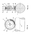
- Fig. 12 shows a roller 4 'with a concave, arcuately curved running surface 60.
- the roller 4 consists of a made of elastic plastic race 61, which is marked cross-hatched in Fig. 12 to 16, and provided with a central axle 63 running body 62, which can be made of plastic or metal.
- Running body 62 and race 61 are positively connected with each other, as can be achieved for example by spraying the race 61 on the running body 62.
- the roller 4 moves on a rail 1 with a circular cross section, so that the roller 4 is in contact with the rail 1 via a circular arcuate curved running surface 60. Size and shape of the contact surface between the tread 60 and rail 1 depend on the elasticity and the pressure load of the race 61 in the contact area.
- a roller 4 has a curved running surface 60, as is the case, for example, with rails 1 with a circular cross-sectional shape, then the effect results that contact points with different radial distances have different peripheral speeds and thus different travel paths. This can lead to friction losses, in particular in the case of elastic running rings 61, which lead to reduced adhesion and possibly even damage to the roll 4 in unfavorable conditions for heating the rolls 4.
- the amount of friction losses depends on the geometric conditions (curvature of the rail cross-section, diameter of the roller), as well as on the load conditions and the elasticity of the material of the roller 4 on the tread 60.
- a higher contact pressure as required in particular for driven or braked rollers 4 for transmitting the acceleration and deceleration forces, leads to an increase in the contact surface and thus to greater friction losses due to different peripheral speeds to lead.
- Rollers 4 conventional design can therefore be suitable for certain applications only conditionally.
- rollers 4 with curved running surfaces 60 which are preferably used within the scope of the invention, are designed in such a way that, on the one hand, friction losses are minimized and, on the other hand, adhesion for the transmission of forces (for example drive or braking forces) is increased.
- the running surface 60 of the race 61 is divided into sections 65 and 66, wherein the sections 65 at the two outer regions and the portion 66 in the central region of the tread 60 is arranged.
- the outer portions 65 are separated from the central portion 66 by recesses 68 (annular grooves). Due to the larger diameter of the running surface 60 in the outer region, the portions 65 have a higher radial peripheral speed than the portion 66.
- the central portion 66 is arranged along the circumference, transverse to the running direction lamellae 67 formed.
- Fig. 16 shows a detail of the roller 4 of Figs. 14 and 15, wherein the rolling operation is shown in a travel in the direction of the arrow 70. It was assumed a contact pressure, which leads to a contact surface extending over three fins 67. Furthermore, it has been assumed that the relative speed of the roller 4 to the rail 1 is determined by the non-profiled portions 65 of the race 61, which have a higher peripheral speed than that of the central portion 66. The lamellae 67 located in the contact region bend backwards, due to the lower peripheral speed, counter to the direction of travel (arrow 70).
- the race 61 can be made in one piece or in several parts from plastics with different properties (hardness, static friction on the rail 1).
- the outer portions 65 of the race 61 may be made of harder plastic and the middle portion 66 of softer plastic.
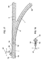
- the target position of the trolley 2 is maintained, in one embodiment in the neutral zones of the rail 1 and the rail branches 6, 7 (which are those areas where the middle roller 4 unrolls, once the trolley 2 has been rotated to the desired position (eg, Fig. 4c and Fig. 8) grooves 102, 103 are provided.
- a locking means 100 which may be formed either as a slider or a roller and is arranged on the trolley 2, engages depending on the rotational position of the trolley 2 in one or the other groove 102, 103 a.
- the latching means 100 is unlocked by the leakage of the grooves 102, 103 at their groove ends 104 and the trolley 2 can be rotated again, so that via the control reverse rotation of the trolley 2 in its normal position (Fig.4a) initiated can be.
- the grooves 102, 103 should have a length that corresponds to the length of the branch 8 itself increased by 2 times the braking distance at maximum speed, maximum load and minimal static friction of the rollers 4 (wet track body).
- the examination of the correct rotational position of the trolley 2 relative to the rail 1 in particular before driving on a branch 8 can also be done without contact.
- guidelines are provided on the rail 1, for example in the form of optically, capacitively or magnetically detectable strips, and in the trolley 2 a sensor detecting the strip is arranged which, when the trolley 2 is rotated to the desired rotational position, sends a corresponding signal to the control emits.
- a transport system has at least one, preferably on Columns or hanging suspended on ropes, rail 1 to which at least one trolley 2 transport carriage 23 are movable.
- a plurality of rollers 4 are provided and the trolley 2 is actively rotated about the axis of the rail 1 relative to the trolley 23.
- Branches 8 are provided in the rail 1, in which the rail 1 divides into two rail branches 6 and 7.
- the rail 1 divides into two rail branches 6 and 7.
- the rail 1 divides into two rail branches 6 and 7.
- the rail 1 divides into two rail branches 6 and 7.
- rollers 4 can be used with a made of elastic plastic race 61 with a curved, the rail 1 adapted in cross-section, tread 60.
- the race 61 is divided into radial portions 65, 66, wherein the central portion 66 is profiled lamellar.
Landscapes
- Engineering & Computer Science (AREA)
- Mechanical Engineering (AREA)
- Architecture (AREA)
- Civil Engineering (AREA)
- Structural Engineering (AREA)
- Transportation (AREA)
- Platform Screen Doors And Railroad Systems (AREA)
- Chain Conveyers (AREA)
- Table Equipment (AREA)
- Carriers, Traveling Bodies, And Overhead Traveling Cranes (AREA)
Claims (24)
- Installation de transport comprenant au moins un rail (1) et au moins un wagonnet de transport (23) qui est déplaçable le long du rail (1) par l'intermédiaire d'au moins un chariot roulant (2), le chariot roulant (2) entourant le rail (1) seulement en partie, présentant une fente (3), étant guidé sur le rail (1) et pouvant tourner autour de l'axe du rail (1) par rapport au wagonnet de transport (23), et au moins un branchement (8) étant prévu dans le rail (1), dans lequel le rail (1) se divise en deux branches (6, 7) de rail, caractérisée en ce que le rail (1) et les branches (6, 7) de rail ont une forme de section circulaire, en ce que dans la partie du branchement (8) des rainures (9, 10) sont prévues aussi bien sur le côté supérieur que sur le côté inférieur du rail (1) et des branches (6, 7) du rail, ces rainures limitant entre elles, sur le côté supérieur et sur le côté inférieur du branchement (8), respectivement une nervure (11) s'amincissant, qui se termine dans la partie du coin (14) entre les branches (6, 7) du rail, et en ce que le chariot roulant (2) peut tourner de manière active.
- Installation de transport selon la revendication 1, caractérisée en ce que les rainures (9, 10) s'étendent en direction des axes (15, 16) des branches (6, 7) du rail.
- Installation de transport selon la revendication 1 ou 2, caractérisée en ce que les rainures (9, 10) possèdent une forme de section essentiellement en forme de U ou de V.
- Installation de transport selon l'une quelconque des revendications 1 à 3, caractérisée en ce que le chariot roulant (2) est guidé sur le rail (1) resp. sur les branches (6, 7) du rail par l'intermédiaire d'au moins trois roulettes (4), par l'intermédiaire de pièces coulissantes, par l'intermédiaire de coussinets d'air et/ou de forces magnétiques.
- Installation de transport selon la revendication 4, caractérisée en ce que les roulettes (4) du chariot roulant (2) incluent entre elles un angle d'environ 120°.
- Installation de transport selon la revendication 5, caractérisée en ce que dans la partie d'un branchement (8), la roulette centrale (4) des trois roulettes (4) du chariot roulant (2) est adjacente à la surface (17, 18) du branchement (8) qui est situé en face de la branche (7, 6) du rail, sur laquelle il n'y a pas à circuler.
- Installation de transport selon l'une quelconque des revendications 1 à 6, caractérisée en ce que les surfaces (12, 13) des nervures (11) sont formées de manière correspondant au contour des branches (6, 7) du rail et en ce que ces surfaces (12, 13), dans la partie du branchement (8), forment des parties des surfaces extérieures des branches (6, 7) du rail.
- Installation de transport selon l'une quelconque des revendications 5 à 7, caractérisée en ce qu'au moins une roulette (4) du chariot roulant (2) est entraînée par rotation.
- Installation de transport selon l'une quelconque des revendications 1 à 8, caractérisée en ce qu'un entraînement (40) est prévu pour faire tourner le chariot roulant (2), au moyen duquel le chariot roulant (2) peut être tourné de telle manière que les roulettes (4) disposées à côté de la fente (3) dans le chariot roulant (2) ont prise dans les rainures (9, 10) mutuellement opposées lorsqu'un branchement (8) est dépassé.
- Installation de transport selon la revendication 9, caractérisée en ce que le chariot roulant (2) peut tourner au moyen d'un organe moteur (40) via une transmission (41, 42).
- Installation de transport selon l'une quelconque des revendications 1 à 8, caractérisée en ce que les roulettes (4) guidant le chariot roulant (2) sur le rail (1) sont réglables par l'intermédiaire d'un organe moteur (50), de telle manière que les roulettes (4) sont inclinées d'un angle (I) par rapport au rail (1) et que le chariot roulant (2) se tourne lors de leur mouvement le long du rail (1).
- Installation de transport selon l'une quelconque des revendications 9 à 11, caractérisée en ce qu'une commande électronique est prévue, laquelle, au moyen de capteurs (M, N), commande l'entraînement (40) destiné à faire tourner le chariot roulant (2), de telle manière que le chariot roulant (2) est tourné en position désirée (H), par rapport au wagonnet de transport (23), pour circuler sur l'une des branches (6, 7) du rail en aval d'un branchement (8).
- Installation de transport selon l'une quelconque des revendications 9 à 11, caractérisée en ce qu'une commande électronique (O) est prévue, laquelle, au moyen de capteurs (M, N), commande un organe moteur (50) de telle manière que les roulettes (4) sont mises dans un angle de réglage (I) de manière inclinée par rapport à l'axe (15) du rail, de telle façon que le chariot roulant (2) est tourné dans la position désirée (H) lorsqu'il circule le long du rail (1).
- Installation de transport selon l'une quelconque des revendications 4 à 13, caractérisée en ce qu'une commande électronique (O) est prévue, laquelle, au moyen de capteurs (M, V) commande un organe moteur (50) de telle manière que les roulettes (4) sont pivotées de telle façon que la voie des roulettes (4) suit la voie de courbe incurvée (W) du rail (1).
- Installation de transport selon l'une quelconque des revendications 1 à 14, caractérisée en ce que, dans la partie d'un branchement (8) et des branches (6, 7) du rail partant du branchement (8), des rainures (103, 104) sont prévues dans le rail (1) et dans les branches (6, 7) du rail, et en ce qu'au moins un moyen d'enclenchement (100), p. ex. une roulette tournant librement, est prévu dans le chariot roulant (2), ce moyen d'enclenchement ayant prise dans l'une des rainures (102, 103) lorsque le chariot roulant (2) est tourné dans la position de rotation nécessaire.
- Installation de transport selon la revendication 15, caractérisée en ce qu'un élément de commutation (101) est attribué au moyen d'enclenchement (100).
- Installation de transport selon la revendication 16, caractérisée en ce que l'élément de commutation (101) est relié à une commande électronique (O) et qu'il enregistre la prise ou la non-prise du moyen d'enclenchement (100) dans l'une des rainures (102, 103).
- Installation de transport selon l'une quelconque des revendications 1 à 17, caractérisée en ce que les rails (1) et éventuellement les branches (6, 7) des rails portent des lignes directrices qui sont enregistrables sans contact par au moins un capteur disposé dans le chariot roulant (2), lorsque le chariot roulant (2) prend la position de rotation respectivement désirée.
- Installation de transport comprenant au moins un rail (1) et au moins un wagonnet de transport (23) qui est déplaçable le long du rail par l'intermédiaire d'au moins un chariot roulant (2) et qui est guidé sur le rail (1) par l'intermédiaire de roulettes (4), selon l'une quelconque des revendications 1 à 17, caractérisée en ce que les surfaces de roulement (60) des roulettes (4) sont incurvées de manière concave en étant congruentes par rapport au contour extérieur du rail (1).
- Installation de transport selon la revendication 19, caractérisée en ce que les roulettes (4) présentent des anneaux de roulement (61) réalisés en matière plastique élastique.
- Installation de transport selon la revendication 19 ou 20, caractérisée en ce que la surface de roulement (60) des anneaux de roulement (61) est divisée en au moins deux sections (65, 66), dont au moins la section centrale (66) présente un profil (67) exécuté transversalement au sens de déplacement (flèche 70).
- Installation de transport selon la revendication 21, caractérisée en ce que la section centrale (66) présente des lamelles (67) transversales à la roulette (4).
- Installation de transport selon la revendication 21 ou 22, caractérisée en ce que les sections (65, 66) de l'anneau de roulement (61) sont constituées de différentes matières synthétiques.
- Installation de transport selon l'une quelconque des revendications 21 à 23, caractérisée en ce que la section centrale (66) est en matériau plus mou que les deux sections extérieures (65) de l'anneau de roulement (61).
Priority Applications (1)
| Application Number | Priority Date | Filing Date | Title |
|---|---|---|---|
| AT01984131T ATE317786T1 (de) | 2000-07-11 | 2001-07-10 | Transportanlage |
Applications Claiming Priority (5)
| Application Number | Priority Date | Filing Date | Title |
|---|---|---|---|
| AT11912000 | 2000-07-11 | ||
| AT11912000A AT410108B (de) | 2000-07-11 | 2000-07-11 | Transportanlage |
| AT6172001 | 2001-04-17 | ||
| AT6172001A AT410301B (de) | 2001-04-17 | 2001-04-17 | Laufrolle, insbesondere für auf rohrförmigen tragschienen geführte transportfahrzeuge |
| PCT/AT2001/000228 WO2002004273A1 (fr) | 2000-07-11 | 2001-07-10 | Systeme de transport |
Publications (2)
| Publication Number | Publication Date |
|---|---|
| EP1299276A1 EP1299276A1 (fr) | 2003-04-09 |
| EP1299276B1 true EP1299276B1 (fr) | 2006-02-15 |
Family
ID=25608368
Family Applications (1)
| Application Number | Title | Priority Date | Filing Date |
|---|---|---|---|
| EP01984131A Expired - Lifetime EP1299276B1 (fr) | 2000-07-11 | 2001-07-10 | Systeme de transport |
Country Status (8)
| Country | Link |
|---|---|
| US (1) | US6935244B2 (fr) |
| EP (1) | EP1299276B1 (fr) |
| JP (1) | JP2004501835A (fr) |
| CN (1) | CN1286688C (fr) |
| AU (2) | AU2002218760B2 (fr) |
| DE (1) | DE50108962D1 (fr) |
| ES (1) | ES2258557T3 (fr) |
| WO (1) | WO2002004273A1 (fr) |
Families Citing this family (14)
| Publication number | Priority date | Publication date | Assignee | Title |
|---|---|---|---|---|
| AT412270B (de) * | 2002-12-19 | 2004-12-27 | Lechner Alexander Dr | Steuereinrichtung einer transportanlage mit wenigstens einem transportwagen und verfahren zum steuern des lenkwinkels der räder |
| CN1291874C (zh) | 2005-04-15 | 2006-12-27 | 杨南征 | 水平电梯个体交通运输系统及其调度方法 |
| AT502080B1 (de) * | 2005-06-13 | 2007-08-15 | Alexander Dr Lechner | Transportanlage |
| USD641943S1 (en) * | 2009-03-18 | 2011-07-19 | Dek International Gmbh | Production line assembly and module |
| CN105329745B (zh) * | 2012-04-26 | 2017-12-08 | 铰接细索列车公司 | 铰接细索列车 |
| CH707798A1 (de) * | 2013-03-28 | 2014-09-30 | Ferag Ag | Schienengeführtes Fördermittel und Förderanlage mit derartigen Fördermitteln. |
| CN103990742B (zh) * | 2014-05-30 | 2016-09-28 | 冯广建 | 一种钢筋成型机的带可移动悬挂机构的弯折装置 |
| JP2020066372A (ja) * | 2018-10-25 | 2020-04-30 | 株式会社エアロネクスト | 飛行体 |
| DE102018009914A1 (de) * | 2018-12-13 | 2020-06-18 | Strothmann Machines & Handling GmbH | Schienen-Flurförderer-System |
| CN110878496B (zh) * | 2019-12-03 | 2021-05-11 | 洛阳网津智能科技有限公司 | 一种架空轨道运输系统及其道岔系统 |
| DE102020001056B3 (de) | 2020-02-19 | 2021-07-15 | Karl Gotschlich Maschinenbau GesmbH | Passive weiche für einschienenbahn und einschienenbahn |
| US11325624B2 (en) | 2020-05-29 | 2022-05-10 | Parallel Systems, Inc. | Electric rail vehicle |
| WO2022192795A2 (fr) | 2021-03-12 | 2022-09-15 | Parallel Systems, Inc. | Véhicule ferroviaire électrique |
| EP4330112A4 (fr) | 2021-04-28 | 2025-04-09 | Parallel Systems, Inc. | Système et/ou procédé de conduite en convoi automatisé |
Family Cites Families (22)
| Publication number | Priority date | Publication date | Assignee | Title |
|---|---|---|---|---|
| US429847A (en) * | 1890-06-10 | Glass-carrier | ||
| US310393A (en) * | 1885-01-06 | Conveyer apparatus | ||
| US583704A (en) * | 1897-06-01 | Gustav henkel and gottfried scheld | ||
| US305060A (en) * | 1884-09-16 | Carrier apparatus | ||
| US994461A (en) * | 1911-04-15 | 1911-06-06 | Henry M Harding | Switch for monorails. |
| US2997003A (en) * | 1960-02-26 | 1961-08-22 | Shepard Niles Crane & Hoist Co | Trolley mechanism |
| US3628462A (en) * | 1969-07-16 | 1971-12-21 | Republic National Bank Of Dall | Vehicle switching apparatus |
| DE1940256C3 (de) | 1969-08-07 | 1975-11-20 | Gustav Georg Veith Gmbh & Co Kg, 8000 Muenchen | Fördereinrichtung, insbesondere für die innerbetriebliche Hängeförderung in der Bekleidungsindustrie |
| JPS5457715A (en) | 1977-10-18 | 1979-05-09 | Kikai Shinko Kyokai | Branch mechanism on car in bestriding sitting type transportation facility |
| CA1094967A (fr) * | 1978-01-06 | 1981-02-03 | Jean-Paul Leger | Rangement de trolleys sur voie de garage |
| JPS54146314A (en) * | 1978-05-09 | 1979-11-15 | Kikai Shinko Kyokai | Vehicle steering apparatus in transport system |
| DE2908369C3 (de) | 1979-03-03 | 1981-10-01 | Röhling Anlagenbau GmbH u. Co, 4390 Gladbeck | Weiche für eine Laufschienen aufweisende Hängebahneinrichtung |
| US4862807A (en) | 1983-07-12 | 1989-09-05 | Cimarron Technology Ltd. | Passive railway switching system |
| DE3546923C2 (de) | 1984-06-05 | 1996-02-15 | Franz Gaertner | Selbsttätige Transportvorrichtung für eine Hängefördervorrichtung |
| DE3605317C1 (en) * | 1986-02-19 | 1987-02-26 | Veit Gmbh & Co | Suspended conveying system |
| DE4201468A1 (de) | 1992-01-21 | 1992-07-23 | Daimler Benz Ag | Bussystem mit integrierter spannungsversorgung fuer teilnehmer des systems |
| DE19546694A1 (de) | 1995-12-14 | 1997-06-19 | Hoerdum Martin | Automatische Schienenkabinenbahn Anlage |
| EP0829578A3 (fr) | 1996-09-16 | 1998-05-13 | Wergles, Marx | Aiguillage pour installation monorail de manutention |
| ES2133226B1 (es) | 1996-09-20 | 2000-04-16 | Saiz Manuel Munoz | Tren monorrail magnetico. |
| KR100250021B1 (ko) | 1996-12-02 | 2000-03-15 | 박태진 | 진로 예약방식과 지선 정차방식을 이용한 개별 궤도 수송 시스템 |
| JPH11222122A (ja) | 1998-02-03 | 1999-08-17 | Shinko Electric Co Ltd | 分岐軌道を備えた搬送設備 |
| DE19806990C2 (de) | 1998-02-19 | 2000-03-09 | Wf Logistik Gmbh | Weiche für eine Fördereinrichtung, insbesondere Hängefördereinrichtung |
-
2001
- 2001-07-10 JP JP2002508954A patent/JP2004501835A/ja active Pending
- 2001-07-10 DE DE50108962T patent/DE50108962D1/de not_active Expired - Fee Related
- 2001-07-10 EP EP01984131A patent/EP1299276B1/fr not_active Expired - Lifetime
- 2001-07-10 AU AU2002218760A patent/AU2002218760B2/en not_active Ceased
- 2001-07-10 CN CN01812622.7A patent/CN1286688C/zh not_active Expired - Fee Related
- 2001-07-10 US US10/332,817 patent/US6935244B2/en not_active Expired - Fee Related
- 2001-07-10 ES ES01984131T patent/ES2258557T3/es not_active Expired - Lifetime
- 2001-07-10 AU AU1876002A patent/AU1876002A/xx active Pending
- 2001-07-10 WO PCT/AT2001/000228 patent/WO2002004273A1/fr not_active Ceased
Also Published As
| Publication number | Publication date |
|---|---|
| US6935244B2 (en) | 2005-08-30 |
| AU2002218760B2 (en) | 2005-04-21 |
| EP1299276A1 (fr) | 2003-04-09 |
| CN1286688C (zh) | 2006-11-29 |
| DE50108962D1 (de) | 2006-04-20 |
| ES2258557T3 (es) | 2006-09-01 |
| AU1876002A (en) | 2002-01-21 |
| US20040089188A1 (en) | 2004-05-13 |
| CN1441737A (zh) | 2003-09-10 |
| JP2004501835A (ja) | 2004-01-22 |
| WO2002004273A1 (fr) | 2002-01-17 |
Similar Documents
| Publication | Publication Date | Title |
|---|---|---|
| EP1299276B1 (fr) | Systeme de transport | |
| DE102014110714B4 (de) | Transportvorrichtung und Schlitten für eine Transportvorrichtung | |
| DE69102768T2 (de) | Transportsystem. | |
| DE3522824C1 (de) | Trag- und Fuehrungssystem fuer ortsveraenderliche Tuer- oder Wandelemente | |
| EP3501878A1 (fr) | Dispositif de transport sous forme d'un moteur linéaire à stator long | |
| DE1294405B (de) | Fuehrungssystem fuer Fahrzeuge mit luftbereiften Laufraedern und Fuehrungsraedern mit vertikaler Achse | |
| WO2017032438A1 (fr) | Système de déplacement pour surfaces cylindriques et/ou surfaces coniques | |
| EP0234543A1 (fr) | Système à force magnétique pour le transport de charges à frottement réduit | |
| EP3464010B1 (fr) | Système de transport à rails et véhicule ferroviaire pour un système de transport à rails | |
| EP0120979B1 (fr) | Convoyeur sur rails | |
| DE3206630A1 (de) | Befoerderungsanlage mit einem seilgeschleppten fahrzeug | |
| EP1507696A1 (fr) | Chassis autogrimpeur destine a des facades, notamment des facades de verre | |
| EP0151965B1 (fr) | Chemin de fer électrique suspendu | |
| DE4025313A1 (de) | Transportsystem angetrieben durch einen linearmotor | |
| EP3479688A1 (fr) | Installation agricole et robot autonome | |
| AT502080B1 (de) | Transportanlage | |
| EP0137471B1 (fr) | Convoyeur d'accumulation à chaîne pour des colis suspendus | |
| EP2390205B1 (fr) | Transporteur modulaire | |
| DE69507133T2 (de) | Vorrichtung bei hängeförderern | |
| DE19641043B4 (de) | Containertransportsystem | |
| DE102020001056B3 (de) | Passive weiche für einschienenbahn und einschienenbahn | |
| AT410108B (de) | Transportanlage | |
| DE3707295C1 (en) | Suspension rail conveyor system | |
| EP3142914B1 (fr) | Dispositif de transport pour transporter des marchandises | |
| DE2235014C3 (de) | Rangierweiche |
Legal Events
| Date | Code | Title | Description |
|---|---|---|---|
| PUAI | Public reference made under article 153(3) epc to a published international application that has entered the european phase |
Free format text: ORIGINAL CODE: 0009012 |
|
| 17P | Request for examination filed |
Effective date: 20021028 |
|
| AK | Designated contracting states |
Kind code of ref document: A1 Designated state(s): AT BE CH CY DE DK ES FI FR GB GR IE IT LI LU MC NL PT SE TR |
|
| AX | Request for extension of the european patent |
Extension state: AL LT LV MK RO SI |
|
| 17Q | First examination report despatched |
Effective date: 20041125 |
|
| GRAP | Despatch of communication of intention to grant a patent |
Free format text: ORIGINAL CODE: EPIDOSNIGR1 |
|
| GRAS | Grant fee paid |
Free format text: ORIGINAL CODE: EPIDOSNIGR3 |
|
| GRAA | (expected) grant |
Free format text: ORIGINAL CODE: 0009210 |
|
| AK | Designated contracting states |
Kind code of ref document: B1 Designated state(s): AT BE CH CY DE DK ES FI FR GB GR IE IT LI LU MC NL PT SE TR |
|
| AX | Request for extension of the european patent |
Extension state: SI |
|
| PG25 | Lapsed in a contracting state [announced via postgrant information from national office to epo] |
Ref country code: FI Free format text: LAPSE BECAUSE OF FAILURE TO SUBMIT A TRANSLATION OF THE DESCRIPTION OR TO PAY THE FEE WITHIN THE PRESCRIBED TIME-LIMIT Effective date: 20060215 |
|
| REG | Reference to a national code |
Ref country code: GB Ref legal event code: FG4D Free format text: NOT ENGLISH Ref country code: CH Ref legal event code: EP |
|
| REG | Reference to a national code |
Ref country code: IE Ref legal event code: FG4D Free format text: LANGUAGE OF EP DOCUMENT: GERMAN |
|
| REF | Corresponds to: |
Ref document number: 50108962 Country of ref document: DE Date of ref document: 20060420 Kind code of ref document: P |
|
| PG25 | Lapsed in a contracting state [announced via postgrant information from national office to epo] |
Ref country code: DK Free format text: LAPSE BECAUSE OF FAILURE TO SUBMIT A TRANSLATION OF THE DESCRIPTION OR TO PAY THE FEE WITHIN THE PRESCRIBED TIME-LIMIT Effective date: 20060515 Ref country code: SE Free format text: LAPSE BECAUSE OF FAILURE TO SUBMIT A TRANSLATION OF THE DESCRIPTION OR TO PAY THE FEE WITHIN THE PRESCRIBED TIME-LIMIT Effective date: 20060515 |
|
| GBT | Gb: translation of ep patent filed (gb section 77(6)(a)/1977) |
Effective date: 20060502 |
|
| REG | Reference to a national code |
Ref country code: CH Ref legal event code: NV Representative=s name: RIEDERER HASLER & PARTNER PATENTANWAELTE AG |
|
| PG25 | Lapsed in a contracting state [announced via postgrant information from national office to epo] |
Ref country code: PT Free format text: LAPSE BECAUSE OF FAILURE TO SUBMIT A TRANSLATION OF THE DESCRIPTION OR TO PAY THE FEE WITHIN THE PRESCRIBED TIME-LIMIT Effective date: 20060717 |
|
| PG25 | Lapsed in a contracting state [announced via postgrant information from national office to epo] |
Ref country code: BE Free format text: LAPSE BECAUSE OF NON-PAYMENT OF DUE FEES Effective date: 20060731 Ref country code: MC Free format text: LAPSE BECAUSE OF NON-PAYMENT OF DUE FEES Effective date: 20060731 |
|
| REG | Reference to a national code |
Ref country code: ES Ref legal event code: FG2A Ref document number: 2258557 Country of ref document: ES Kind code of ref document: T3 |
|
| ET | Fr: translation filed | ||
| PLBE | No opposition filed within time limit |
Free format text: ORIGINAL CODE: 0009261 |
|
| STAA | Information on the status of an ep patent application or granted ep patent |
Free format text: STATUS: NO OPPOSITION FILED WITHIN TIME LIMIT |
|
| 26N | No opposition filed |
Effective date: 20061116 |
|
| BERE | Be: lapsed |
Owner name: LECHNER, ALEXANDER Effective date: 20060731 Owner name: WOTKE, ANDREAS Effective date: 20060731 |
|
| PG25 | Lapsed in a contracting state [announced via postgrant information from national office to epo] |
Ref country code: GR Free format text: LAPSE BECAUSE OF FAILURE TO SUBMIT A TRANSLATION OF THE DESCRIPTION OR TO PAY THE FEE WITHIN THE PRESCRIBED TIME-LIMIT Effective date: 20060516 |
|
| PG25 | Lapsed in a contracting state [announced via postgrant information from national office to epo] |
Ref country code: LU Free format text: LAPSE BECAUSE OF NON-PAYMENT OF DUE FEES Effective date: 20060710 |
|
| PGFP | Annual fee paid to national office [announced via postgrant information from national office to epo] |
Ref country code: CH Payment date: 20080709 Year of fee payment: 8 Ref country code: ES Payment date: 20080714 Year of fee payment: 8 |
|
| PG25 | Lapsed in a contracting state [announced via postgrant information from national office to epo] |
Ref country code: CY Free format text: LAPSE BECAUSE OF FAILURE TO SUBMIT A TRANSLATION OF THE DESCRIPTION OR TO PAY THE FEE WITHIN THE PRESCRIBED TIME-LIMIT Effective date: 20060215 |
|
| PGFP | Annual fee paid to national office [announced via postgrant information from national office to epo] |
Ref country code: FR Payment date: 20080711 Year of fee payment: 8 Ref country code: IE Payment date: 20080707 Year of fee payment: 8 Ref country code: NL Payment date: 20080715 Year of fee payment: 8 |
|
| PGFP | Annual fee paid to national office [announced via postgrant information from national office to epo] |
Ref country code: AT Payment date: 20090729 Year of fee payment: 9 Ref country code: DE Payment date: 20090923 Year of fee payment: 9 Ref country code: GB Payment date: 20090708 Year of fee payment: 9 Ref country code: TR Payment date: 20090707 Year of fee payment: 9 |
|
| REG | Reference to a national code |
Ref country code: CH Ref legal event code: PL |
|
| NLV4 | Nl: lapsed or anulled due to non-payment of the annual fee |
Effective date: 20100201 |
|
| REG | Reference to a national code |
Ref country code: FR Ref legal event code: ST Effective date: 20100331 |
|
| PG25 | Lapsed in a contracting state [announced via postgrant information from national office to epo] |
Ref country code: CH Free format text: LAPSE BECAUSE OF NON-PAYMENT OF DUE FEES Effective date: 20090731 Ref country code: LI Free format text: LAPSE BECAUSE OF NON-PAYMENT OF DUE FEES Effective date: 20090731 Ref country code: FR Free format text: LAPSE BECAUSE OF NON-PAYMENT OF DUE FEES Effective date: 20090731 |
|
| PGFP | Annual fee paid to national office [announced via postgrant information from national office to epo] |
Ref country code: IT Payment date: 20090729 Year of fee payment: 9 |
|
| PG25 | Lapsed in a contracting state [announced via postgrant information from national office to epo] |
Ref country code: IE Free format text: LAPSE BECAUSE OF NON-PAYMENT OF DUE FEES Effective date: 20090710 |
|
| REG | Reference to a national code |
Ref country code: ES Ref legal event code: FD2A Effective date: 20090711 |
|
| PG25 | Lapsed in a contracting state [announced via postgrant information from national office to epo] |
Ref country code: ES Free format text: LAPSE BECAUSE OF NON-PAYMENT OF DUE FEES Effective date: 20090711 |
|
| GBPC | Gb: european patent ceased through non-payment of renewal fee |
Effective date: 20100710 |
|
| PG25 | Lapsed in a contracting state [announced via postgrant information from national office to epo] |
Ref country code: DE Free format text: LAPSE BECAUSE OF NON-PAYMENT OF DUE FEES Effective date: 20110201 |
|
| REG | Reference to a national code |
Ref country code: DE Ref legal event code: R119 Ref document number: 50108962 Country of ref document: DE Effective date: 20110201 |
|
| PG25 | Lapsed in a contracting state [announced via postgrant information from national office to epo] |
Ref country code: IT Free format text: LAPSE BECAUSE OF NON-PAYMENT OF DUE FEES Effective date: 20100710 Ref country code: AT Free format text: LAPSE BECAUSE OF NON-PAYMENT OF DUE FEES Effective date: 20100710 |
|
| PG25 | Lapsed in a contracting state [announced via postgrant information from national office to epo] |
Ref country code: GB Free format text: LAPSE BECAUSE OF NON-PAYMENT OF DUE FEES Effective date: 20100710 |
|
| PG25 | Lapsed in a contracting state [announced via postgrant information from national office to epo] |
Ref country code: NL Free format text: LAPSE BECAUSE OF NON-PAYMENT OF DUE FEES Effective date: 20100201 |
|
| PG25 | Lapsed in a contracting state [announced via postgrant information from national office to epo] |
Ref country code: TR Free format text: LAPSE BECAUSE OF NON-PAYMENT OF DUE FEES Effective date: 20100710 |