EP1300629A1 - Rail électrique pour lampes - Google Patents
Rail électrique pour lampes Download PDFInfo
- Publication number
- EP1300629A1 EP1300629A1 EP02018609A EP02018609A EP1300629A1 EP 1300629 A1 EP1300629 A1 EP 1300629A1 EP 02018609 A EP02018609 A EP 02018609A EP 02018609 A EP02018609 A EP 02018609A EP 1300629 A1 EP1300629 A1 EP 1300629A1
- Authority
- EP
- European Patent Office
- Prior art keywords
- busbar
- supply lines
- conductor rail
- laminating device
- rail system
- Prior art date
- Legal status (The legal status is an assumption and is not a legal conclusion. Google has not performed a legal analysis and makes no representation as to the accuracy of the status listed.)
- Granted
Links
- 239000004020 conductor Substances 0.000 title claims description 22
- 239000011810 insulating material Substances 0.000 claims abstract description 43
- 238000000576 coating method Methods 0.000 claims abstract description 7
- 239000011248 coating agent Substances 0.000 claims abstract description 6
- 238000010030 laminating Methods 0.000 claims description 100
- 238000003475 lamination Methods 0.000 claims description 6
- 239000000463 material Substances 0.000 description 5
- 230000001681 protective effect Effects 0.000 description 4
- 230000007935 neutral effect Effects 0.000 description 3
- 208000031872 Body Remains Diseases 0.000 description 1
- RYGMFSIKBFXOCR-UHFFFAOYSA-N Copper Chemical compound [Cu] RYGMFSIKBFXOCR-UHFFFAOYSA-N 0.000 description 1
- 230000006978 adaptation Effects 0.000 description 1
- 239000000969 carrier Substances 0.000 description 1
- 238000009500 colour coating Methods 0.000 description 1
- 229910052802 copper Inorganic materials 0.000 description 1
- 239000010949 copper Substances 0.000 description 1
- 230000003247 decreasing effect Effects 0.000 description 1
- 238000009434 installation Methods 0.000 description 1
- 238000009413 insulation Methods 0.000 description 1
- 238000002955 isolation Methods 0.000 description 1
- 238000000034 method Methods 0.000 description 1
- 230000003287 optical effect Effects 0.000 description 1
- 238000004806 packaging method and process Methods 0.000 description 1
- 230000006641 stabilisation Effects 0.000 description 1
- 238000011105 stabilization Methods 0.000 description 1
- 239000000725 suspension Substances 0.000 description 1
- 230000000007 visual effect Effects 0.000 description 1
Images





Classifications
-
- H—ELECTRICITY
- H01—ELECTRIC ELEMENTS
- H01R—ELECTRICALLY-CONDUCTIVE CONNECTIONS; STRUCTURAL ASSOCIATIONS OF A PLURALITY OF MUTUALLY-INSULATED ELECTRICAL CONNECTING ELEMENTS; COUPLING DEVICES; CURRENT COLLECTORS
- H01R25/00—Coupling parts adapted for simultaneous co-operation with two or more identical counterparts, e.g. for distributing energy to two or more circuits
- H01R25/14—Rails or bus-bars constructed so that the counterparts can be connected thereto at any point along their length
- H01R25/142—Their counterparts
-
- F—MECHANICAL ENGINEERING; LIGHTING; HEATING; WEAPONS; BLASTING
- F21—LIGHTING
- F21V—FUNCTIONAL FEATURES OR DETAILS OF LIGHTING DEVICES OR SYSTEMS THEREOF; STRUCTURAL COMBINATIONS OF LIGHTING DEVICES WITH OTHER ARTICLES, NOT OTHERWISE PROVIDED FOR
- F21V21/00—Supporting, suspending, or attaching arrangements for lighting devices; Hand grips
- F21V21/002—Supporting, suspending, or attaching arrangements for lighting devices; Hand grips making direct electrical contact, e.g. by piercing
-
- F—MECHANICAL ENGINEERING; LIGHTING; HEATING; WEAPONS; BLASTING
- F21—LIGHTING
- F21V—FUNCTIONAL FEATURES OR DETAILS OF LIGHTING DEVICES OR SYSTEMS THEREOF; STRUCTURAL COMBINATIONS OF LIGHTING DEVICES WITH OTHER ARTICLES, NOT OTHERWISE PROVIDED FOR
- F21V21/00—Supporting, suspending, or attaching arrangements for lighting devices; Hand grips
- F21V21/34—Supporting elements displaceable along a guiding element
- F21V21/35—Supporting elements displaceable along a guiding element with direct electrical contact between the supporting element and electric conductors running along the guiding element
-
- F—MECHANICAL ENGINEERING; LIGHTING; HEATING; WEAPONS; BLASTING
- F21—LIGHTING
- F21V—FUNCTIONAL FEATURES OR DETAILS OF LIGHTING DEVICES OR SYSTEMS THEREOF; STRUCTURAL COMBINATIONS OF LIGHTING DEVICES WITH OTHER ARTICLES, NOT OTHERWISE PROVIDED FOR
- F21V23/00—Arrangement of electric circuit elements in or on lighting devices
- F21V23/06—Arrangement of electric circuit elements in or on lighting devices the elements being coupling devices, e.g. connectors
-
- H—ELECTRICITY
- H01—ELECTRIC ELEMENTS
- H01R—ELECTRICALLY-CONDUCTIVE CONNECTIONS; STRUCTURAL ASSOCIATIONS OF A PLURALITY OF MUTUALLY-INSULATED ELECTRICAL CONNECTING ELEMENTS; COUPLING DEVICES; CURRENT COLLECTORS
- H01R4/00—Electrically-conductive connections between two or more conductive members in direct contact, i.e. touching one another; Means for effecting or maintaining such contact; Electrically-conductive connections having two or more spaced connecting locations for conductors and using contact members penetrating insulation
- H01R4/24—Connections using contact members penetrating or cutting insulation or cable strands
- H01R4/2404—Connections using contact members penetrating or cutting insulation or cable strands the contact members having teeth, prongs, pins or needles penetrating the insulation
- H01R4/2406—Connections using contact members penetrating or cutting insulation or cable strands the contact members having teeth, prongs, pins or needles penetrating the insulation having needles or pins
Definitions
- the present invention relates to a busbar system for Luminaires, in particular a high-voltage busbar system, comprising at least one elastic busbar, the Having supply lines that are of an elastic, surrounded band-shaped insulating material, wherein the Busbar system further at least one adapter unit comprising, passing through the band-shaped insulating material Contact elements for the electrically conductive contacting of the Supply lines and a connection area for the Has connection with at least one lamp. Furthermore the present invention such a busbar system, the according to the preamble of claim 2 no band-shaped Insulating material includes.
- Busbar systems of the type mentioned are in particular Well known from the outside.
- elastic busbars are usually one Plastic material that is splashed around two supply lines is. Due to its material properties exhibit the elastic Busbars from the prior art one pronounced unattractive, mostly even porous surface.
- the problem underlying the present invention is the Creation of a busbar system of the type mentioned, which offers a visually appealing appearance and is flexible.
- the Busbar system further preferably a flexible Laminating device comprising the band-shaped insulating material and / or the supply lines at least in sections surrounds.
- a laminating device can the visually unattractive appearance of the band-shaped Insulating or the supply lines are laminated, so that the busbar in terms of their appearance clearly is upgraded.
- band-shaped insulating material can on the inside of the laminating device, preferably integrally formed Be provided grooves for the supply lines.
- Be provided grooves for the supply lines.
- the band-shaped insulating material of the Laminating be substantially completely surrounded.
- Invention can the laminating on its outside be coated, in particular with a metallic coating.
- a metallic coating By such a coating, any materials be modeled.
- brass-like, chrome-like or titan-like Surfaces are created, which are the exterior of the Visually upgrade busbar system.
- the laminating of the strip-shaped insulating material and / or the supply lines can be removed and in a flat spread form can be transferred. Due to the possibility of decreasing the Laminating device can be easily exchanged laminators so that the outer generated by the busbar system Impression can be arbitrarily adapted to the market requirements.
- the laminating device is removed in the process Condition rollable.
- the laminating device can be store in the smallest space.
- the Laminating as at least partially bendable Be formed rod material.
- the laminating device can be made of the planar Condition by flaps around a hinge, in particular a Film hinge around the band-shaped insulating material and / or around the Supply lines are closed around.
- the laminating device can consist of two halves which surround the band-shaped insulating material and / or the supply lines around can be connected to each other. In both cases results locally by the user a very easy to install the Busbar system.
- Invention are on the outside of the laminating device Passage openings provided for the contact elements. These Through openings allow contacting the Supply lines, without doing the laminating device is damaged.
- the contact elements of insulating rings surrounded, which can intervene so in the through-openings, that the contact elements are electrically isolated from the Laminating passed through the access openings can be.
- the isolation of the contact elements opposite the laminating device is avoided, for example, by a metallic coating of the laminating the individual Contact elements are electrically connected to each other, wherein then the danger of a short circuit would exist.
- the adapter unit a body having a recess into which the busbar can be introduced, wherein in this recess the Protruding contact elements from the body.
- the Adapter unit comprise a cover, by attaching and Set on the body a secure contacting one in the Recess incorporated busbar can be guaranteed. By this measure, by simply inserting the Busbar in the recess and corresponding example Pressing and latching the lid the supply lines of the contact elements are contacted.
- the adapter unit comprises a body with two interconnected halves, between which the recess can be formed. Also in this way can be a simple and secure attachment and contacting one in the recess introduced busbar be ensured.
- the adapter unit a cover plate, the slots for the passage of the Contact elements has.
- This cover can on the one hand for Stabilization and on the other to protect the contact elements serve.
- Laminating elements are provided, the individual parts of the Can conceal busbar system.
- Both Laminating elements can be on the one hand Act adapter laminations that can hide the adapter.
- To the the laminating elements can also be used for laminating Ceiling carriers or feeds serve.
- These Laminating elements can be provided with different decors be, so that thereby the visual impression of the corresponding to laminating parts in a simple manner is changeable.
- the Busbar system comprises at least one end piece, which on a End of the busbar applicable, especially at this is screwed.
- This can on the tail a decorative cap be postponed.
- the tail ensures that the one Voltage of 230 V leading supply lines to the unintentional access by the user.
- the Decorative cap can make this functional tail according to the selected design of the busbar be decorative covered.
- the busbar system is three Supply lines equipped, taking to the necessary Neutral and the phase is added to a protective conductor. Especially You can also use two lighting groups via three supply lines be controlled when the protective conductor by another phase is replaced.
- the adapter unit with the equip appropriate amount of contact elements, wherein an adaptation to two lighting groups may be provided can.
- an inventive comprises Busbar system supply lines 1, by a band-shaped insulating material 2 are surrounded, in turn, by a Laminating device 3 is surrounded.
- the invention Busbar system further comprises adapter units 4, with in the following to be described in more detail the means Supply lines 1 through the laminating device 3 and the Band-shaped insulating material 2 can contact through.
- To the Adapter units 4 are lights 5, for example in the form of a Spotlight attached.
- the supply lines 1, the band-shaped insulating material 2 and the laminating device 3 existing busbar by means of a this busbar encompassing ceiling support 6 on the ceiling a room is fastened.
- an infeed 7 can be seen, which is essentially a Power supply cable and an adapter unit includes, like the Adapter unit 4 grab around the laminating device 3 and the Supply line 1 can contact electrically.
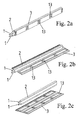
- the two supply lines 1 are of the surrounded band-shaped insulating material 2.
- the band-shaped insulating material has a in substantial rectangular cross-section on.
- the band-shaped Insulating material 2 is particularly elastic, so that the Busbar is arbitrarily bendable. From Fig. 2a it can be seen that in Use state, the laminating device 3, the band-shaped Insulating material 2 completely surrounds. That's why it rejects Fig. 2a apparent laminating device 3 also in the essential rectangular outline.
- the laminating device 3 can have any external surfaces exhibit.
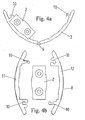
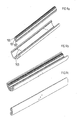
- Fig. 4a and Fig. 4b are two different Laminating devices 3, 8 can be seen in different ways and manner removed from the band-shaped insulating material 2 can be.
- the laminating device 3 shown in FIG. 4 a can be opened and closed by means of a film hinge 9. With help of locking elements 10 which are connected to the of the film hinge. 9 opposite sides of the laminating device 3 are mounted, can the laminating device 3 to the band-shaped insulating material. 2 be clipped around.
- the laminating device 8 shown in FIG. 4b consists of two separable halves 11, 12. These are by means of each facing each other locking elements 10 to the band-shaped Insulating material 2 around each other verclipsbar.
- Fig. 2a From Fig. 2a is further apparent that the laminating device 3rd Passage openings 13 has.
- the laminating device 8 has, Although this is not apparent from Fig. 4b, also such Passage openings 13.
- each groups of access openings 13 formed each of these groups four through openings 13th has, which are arranged in the corners of a square.
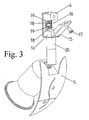
- an adapter unit 4 can be seen, with a as Emitter trained lamp 5 is connected.
- the adapter opening 4 comprises a body 14 to which a lid 15 hingedly attached is. Instead of hinged by means of a hinge connection between body 14 and cover 15 is also a connection conceivable in which the lid 15 in corresponding suspension means of the body 14 can be hung.
- the body 14 has an im essentially rectangular recess 16, into which the out Laminating device 3, 8, band-shaped insulating material 2 and Supply lines 1 existing busbar introduced can be (see for example also Fig. 1). After this Introducing the busbar in the recess 16 is the lid Folded 15 to the body 14 and, for example by means of a Screw 17 is fixed to the body 14.
- the busbar is thereby inserted into the recess 16, that the insulating rings 19 in each case into the through openings 13 into it and protrude through them.
- the busbar is so against the mandrel-shaped Contact elements 18 pressed that their tips through the strip-shaped insulating material penetrate into the supply lines 1 and therein a conductive wire made of, for example, copper to contact.
- the contact elements 18 are via suitable connecting lines in the adapter unit 4 via a connection region of Adapter unit 4 with the radiator support 20 of the radiator running lamp 5 connected.
- the in the passage openings 13 protruding insulating rings 19 ensure that even with a metallic coating of the laminating device 3, 8 no electrically conductive connection between the individual Contact elements 18 occurs.
- the busbar system according to the invention may be in particular to act a high-voltage busbar system.
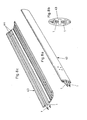
- FIG. 5 furthermore shows an end piece 22 imaged on the end of the by the laminating device 21, the insulating material 20, the insulating material 2 and the Supply lines 1 formed busbar be plugged can.
- On the end piece 22 may after its attachment to the Laminating device 21 additionally a decorative cap 23rd be deferred.
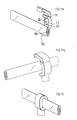
- the attachment of the end piece 22 to the Laminating device 21 can be done by a screw 24, the through a bore 25 in the end piece 22 in the laminating device 21 can be screwed.
- the Insulating material 2 and the supply lines 1 formed Busbar a ceiling support 27 shown, at least different in appearance from the ceiling support 6.
- the ceiling support 27 has a receiving part 28 a loop-like receiving opening 29.
- the eyelike Receiving opening 29 corresponds in terms of their size and their Form the cross section of the laminating device 21 such that the Laminating device 21 fitting from the receiving opening 29th can be included.
- the receiving part 28 can thus in Be moved longitudinally of the busbar.
- a Grub screw 30 through a threaded hole 31 in the Receiving part 28 can reach through, the receiving part 28 and so that the ceiling support 27 are fixed to the power rail.
- the ceiling support 27 also has a vertical support 32 which For example, also by a grub screw with a Ceiling fixture 33 can be connected to the ceiling a room can be screwed on.
- FIG. 7 shows a further embodiment of an adapter unit 34 can be seen, which can also serve to hold a spotlight.
- the adapter unit 34 comprises a body consisting of two halves 35, 36 consists, for example, by means of screws 37 with each other are connectable.
- At the half 35 is pictured in the Embodiment of the beginning of a radiator support 20th mounted according to the adapter unit 4 according to FIG a holder designed as a lamp 5 can hold.
- an installation means with contact elements 38 be included, in contrast to those of Figure 3 apparent contact elements 18 not of an annular Insulation are surrounded. Rather, can on the contact elements 38th a cover plate 39 are plugged, which has slots 40, through which the contact elements 38 can protrude.
- the Cover 39 may be on the outside of the Laminating device 21 abut, such that the Contact elements 38 protrude through the through openings 26. The cover 39 serves to stabilize and protect the Contact elements 38.
- the Busbar by the laminating device 21, the Insulating material 2 and the supply lines 1 is formed from a recess 16 are received in the assembled state of the adapter unit 34 between the both halves 35, 36 of the body remains. In particular, it can the busbar on one side of the cover 39 and on the other side of the half 36 abut.
- FIG. 7 also shows clip-on adapter liners 41, 42 apparent, the shape of the halves 35, 36 of the body of the Adapter unit 34 are adapted.
- the adapter liners 41, 42 can be provided with different decors, so that thereby the optical impression of the adapter unit in a simple way and is changeable.
- FIG. 8a to Figure 8c is another embodiment of a Laminating device 43 can be seen.
- the bus bar only from the laminating device 43 and through Supply lines 1 formed in on the inside of the Laminating 43 integrally formed grooves 44 can be introduced are.
- In this embodiment is on the band-shaped Insulating 2 omitted.
- the laminating 43rd be foldable and sixteenklipsbar configured.
- Busbars in directions perpendicular to their longitudinal extent can be bent over.
- a can also be horizontally under a ceiling of a room extending upright standing busbar, as shown for example in FIG is bent over a corresponding radius such that For example, it runs vertically downwards in the area of a wall.
- the right angle of the two perpendicular to each other standing sections of the busbar surrounds, more or less be chosen large.
- Figs. 9a to 9c is an alternative embodiment of a Busbar system according to the invention with three Supply lines, comprising a neutral 100, a phase 102 and a protective conductor 101 shown. According to the number the supply lines are holes 103 in the wall of the Laminating device provided.
- Fig. 10 is an inventive busbar system with three Supply lines comprising neutral 100, phase 102 and Protective conductor 101 shown, wherein a lamp 5 via a Adapter unit 110 is attached to the busbar system.
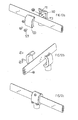
- FIGS. 11a to 11c each show the foldable adapter unit 110 for three supply lines shown.
- the structure of the adapter unit 110 is substantially the same as in the embodiment of FIG two supply lines, except that three contact elements 111, 112, 113 are provided, with the corresponding Supply lines can be contacted.
- Figs. 11b and 11c the essential mounting positions are shown, wherein the Adapter unit 110 initially in the unfolded state on the Power rail is brought and thereafter, as shown in Fig. 11c closed and closed by a corresponding locking mechanism in the Adapter unit 110 is clipped.
- FIGS. 12a to 12c show an adapter unit 120 which essentially resembles the adapter unit 110, however not foldable but screwed is executed. There are three Screws 121 provided in corresponding holes can be screwed and thus a secure hold of the adapter unit 120 can guarantee.
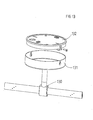
- an adapter unit 130 is shown, the Power supply is provided in the busbar system. in the important here is the adapter unit 130 for connection to in This embodiment provides three supply lines. Furthermore, the adapter unit 130 with a cover 131 connected, in turn, with a base plate 132 for Ceiling mounting is connectable.
- Fig. 14 is an adapter unit 140 for double feed shown. According to a corresponding standard can over a Feeding point maximum 800 W are fed. In the way of Double feed, the power can be doubled. Conceivable are therefore also triple or multiple feeds to one to feed desired power into the busbar system can. Furthermore, here is a corresponding cover shell 141 provided, for example, with a ceiling attachable base plate 142 is connectable.
Landscapes
- Engineering & Computer Science (AREA)
- General Engineering & Computer Science (AREA)
- Installation Of Bus-Bars (AREA)
- Installation Of Indoor Wiring (AREA)
Applications Claiming Priority (6)
| Application Number | Priority Date | Filing Date | Title |
|---|---|---|---|
| DE20116392U | 2001-10-05 | ||
| DE20116392U DE20116392U1 (de) | 2001-10-05 | 2001-10-05 | Stromschienensystem für Leuchten |
| DE20205511U DE20205511U1 (de) | 2001-10-05 | 2002-04-09 | Stromschienensystem für Leuchten |
| DE20205511U | 2002-04-09 | ||
| DE20210092U | 2002-06-29 | ||
| DE20210092U DE20210092U1 (de) | 2001-10-05 | 2002-06-29 | Stromschienensystem für Leuchten |
Publications (2)
| Publication Number | Publication Date |
|---|---|
| EP1300629A1 true EP1300629A1 (fr) | 2003-04-09 |
| EP1300629B1 EP1300629B1 (fr) | 2004-11-03 |
Family
ID=27219631
Family Applications (1)
| Application Number | Title | Priority Date | Filing Date |
|---|---|---|---|
| EP02018609A Expired - Lifetime EP1300629B1 (fr) | 2001-10-05 | 2002-08-20 | Rail électrique pour lampes |
Country Status (2)
| Country | Link |
|---|---|
| EP (1) | EP1300629B1 (fr) |
| AT (1) | ATE281630T1 (fr) |
Cited By (3)
| Publication number | Priority date | Publication date | Assignee | Title |
|---|---|---|---|---|
| WO2013110586A1 (fr) * | 2012-01-26 | 2013-08-01 | Zumtobel Lighting Gmbh | Rampe d'éclairage munie de modules d'éclairage pour éclairage indirect |
| RU220999U1 (ru) * | 2023-06-16 | 2023-10-13 | Общество с ограниченной ответственностью "Транзистор.ру" | Распределительное устройство для шинопровода трековой осветительной системы |
| US11846397B1 (en) * | 2023-04-19 | 2023-12-19 | Hima Lighting Technical Co., Ltd | Strip-type lamp assembly |
Citations (4)
| Publication number | Priority date | Publication date | Assignee | Title |
|---|---|---|---|---|
| EP0734108A2 (fr) * | 1995-03-23 | 1996-09-25 | IDL Industrie- und Design Licht GmbH | Système à rails conducteurs d'éclairage |
| DE29706678U1 (de) * | 1997-04-15 | 1997-07-10 | Pöllet, Wilfried, 90596 Schwanstetten | Strahlerschiene |
| DE29723006U1 (de) * | 1997-12-31 | 1998-02-26 | Josef Sölken GmbH & Co KG, 59759 Arnsberg | Stromschienensystem |
| DE20021009U1 (de) * | 2000-12-12 | 2001-06-28 | Schlagheck Design GmbH, 81539 München | Hochvoltlichtschienensystem |
-
2002
- 2002-08-20 EP EP02018609A patent/EP1300629B1/fr not_active Expired - Lifetime
- 2002-08-20 AT AT02018609T patent/ATE281630T1/de not_active IP Right Cessation
Patent Citations (4)
| Publication number | Priority date | Publication date | Assignee | Title |
|---|---|---|---|---|
| EP0734108A2 (fr) * | 1995-03-23 | 1996-09-25 | IDL Industrie- und Design Licht GmbH | Système à rails conducteurs d'éclairage |
| DE29706678U1 (de) * | 1997-04-15 | 1997-07-10 | Pöllet, Wilfried, 90596 Schwanstetten | Strahlerschiene |
| DE29723006U1 (de) * | 1997-12-31 | 1998-02-26 | Josef Sölken GmbH & Co KG, 59759 Arnsberg | Stromschienensystem |
| DE20021009U1 (de) * | 2000-12-12 | 2001-06-28 | Schlagheck Design GmbH, 81539 München | Hochvoltlichtschienensystem |
Cited By (4)
| Publication number | Priority date | Publication date | Assignee | Title |
|---|---|---|---|---|
| WO2013110586A1 (fr) * | 2012-01-26 | 2013-08-01 | Zumtobel Lighting Gmbh | Rampe d'éclairage munie de modules d'éclairage pour éclairage indirect |
| US11846397B1 (en) * | 2023-04-19 | 2023-12-19 | Hima Lighting Technical Co., Ltd | Strip-type lamp assembly |
| RU220999U1 (ru) * | 2023-06-16 | 2023-10-13 | Общество с ограниченной ответственностью "Транзистор.ру" | Распределительное устройство для шинопровода трековой осветительной системы |
| RU221029U1 (ru) * | 2023-06-16 | 2023-10-16 | Общество с ограниченной ответственностью "Транзистор.ру" | Устройство крепления светильника на шинопровод |
Also Published As
| Publication number | Publication date |
|---|---|
| ATE281630T1 (de) | 2004-11-15 |
| EP1300629B1 (fr) | 2004-11-03 |
Similar Documents
| Publication | Publication Date | Title |
|---|---|---|
| EP2220965B1 (fr) | Rails de profil de support et système de présentation | |
| EP3596789B1 (fr) | Douille provisoire à encastrement plan dans le plafond pour un appareil d'éclairage provisoire et permanent | |
| EP3557121B1 (fr) | Système d'éclairage ainsi que procédé de montage d'un système d'éclairage | |
| AT523560B1 (de) | Leuchtenadapter und Schienenleuchtensystem | |
| DE20205511U1 (de) | Stromschienensystem für Leuchten | |
| EP1282929B1 (fr) | Cablage d'un systeme de meuble modulaire | |
| DE20210092U1 (de) | Stromschienensystem für Leuchten | |
| EP1300629B1 (fr) | Rail électrique pour lampes | |
| EP4007084B1 (fr) | Système de rail porteur pour luminaires ou autres unités électriques | |
| EP2431659A1 (fr) | Lampe de projecteur | |
| DE3807504A1 (de) | Beleuchtungseinrichtung | |
| DE202013009257U1 (de) | Schalteinrichtung für Möbelbeleuchtungen | |
| DE69419972T2 (de) | Distributionskanal einschliesslich Terminalanordnungen | |
| EP0882851A2 (fr) | Unité d'alimentation pour chambre d'hÔpital | |
| EP3453942B1 (fr) | Support mural et kit de fixation | |
| DE8901448U1 (de) | Wandspiegel mit Beleuchtungseinrichtung | |
| DE3907607A1 (de) | Einrichtungsgegenstand, insbesondere duschabtrennung mit einem schwenkelement | |
| DE102016121435B3 (de) | Elektrifiziertes steckhülsenbasiertes Trägersystem | |
| DE4419310C2 (de) | Haltevorrichtung für Geräte der Unterhaltungselektronik, insbesondere HiFi-Anlagen und/oder TV-Geräte | |
| DE10140707A1 (de) | Installationseinrichtung für Leuchten | |
| EP1841013A1 (fr) | Dispositif d'éclairage | |
| DE3637614A1 (de) | Flaechenhaftes beleuchtungssystem | |
| EP3364099B1 (fr) | Luminaire modulaire comprenant une proportion directe et indirecte | |
| DE19757749C2 (de) | Befestigungsprofil für elektrische Geräte | |
| DE3709641A1 (de) | Leuchtensystem |
Legal Events
| Date | Code | Title | Description |
|---|---|---|---|
| PUAI | Public reference made under article 153(3) epc to a published international application that has entered the european phase |
Free format text: ORIGINAL CODE: 0009012 |
|
| AK | Designated contracting states |
Kind code of ref document: A1 Designated state(s): AT BE BG CH CY CZ DE DK EE ES FI FR GB GR IE IT LI LU MC NL PT SE SK TR |
|
| AX | Request for extension of the european patent |
Extension state: AL LT LV MK RO SI |
|
| 17P | Request for examination filed |
Effective date: 20030801 |
|
| 17Q | First examination report despatched |
Effective date: 20030925 |
|
| AKX | Designation fees paid |
Designated state(s): AT BE BG CH CY CZ DE DK EE ES FI FR GB GR IE IT LI LU MC NL PT SE SK TR |
|
| GRAP | Despatch of communication of intention to grant a patent |
Free format text: ORIGINAL CODE: EPIDOSNIGR1 |
|
| GRAS | Grant fee paid |
Free format text: ORIGINAL CODE: EPIDOSNIGR3 |
|
| GRAA | (expected) grant |
Free format text: ORIGINAL CODE: 0009210 |
|
| AK | Designated contracting states |
Kind code of ref document: B1 Designated state(s): AT BE BG CH CY CZ DE DK EE ES FI FR GB GR IE IT LI LU MC NL PT SE SK TR |
|
| PG25 | Lapsed in a contracting state [announced via postgrant information from national office to epo] |
Ref country code: IT Free format text: LAPSE BECAUSE OF FAILURE TO SUBMIT A TRANSLATION OF THE DESCRIPTION OR TO PAY THE FEE WITHIN THE PRESCRIBED TIME-LIMIT;WARNING: LAPSES OF ITALIAN PATENTS WITH EFFECTIVE DATE BEFORE 2007 MAY HAVE OCCURRED AT ANY TIME BEFORE 2007. THE CORRECT EFFECTIVE DATE MAY BE DIFFERENT FROM THE ONE RECORDED. Effective date: 20041103 Ref country code: CZ Free format text: LAPSE BECAUSE OF FAILURE TO SUBMIT A TRANSLATION OF THE DESCRIPTION OR TO PAY THE FEE WITHIN THE PRESCRIBED TIME-LIMIT Effective date: 20041103 Ref country code: BG Free format text: LAPSE BECAUSE OF FAILURE TO SUBMIT A TRANSLATION OF THE DESCRIPTION OR TO PAY THE FEE WITHIN THE PRESCRIBED TIME-LIMIT Effective date: 20041103 Ref country code: EE Free format text: LAPSE BECAUSE OF FAILURE TO SUBMIT A TRANSLATION OF THE DESCRIPTION OR TO PAY THE FEE WITHIN THE PRESCRIBED TIME-LIMIT Effective date: 20041103 Ref country code: FI Free format text: LAPSE BECAUSE OF FAILURE TO SUBMIT A TRANSLATION OF THE DESCRIPTION OR TO PAY THE FEE WITHIN THE PRESCRIBED TIME-LIMIT Effective date: 20041103 Ref country code: NL Free format text: LAPSE BECAUSE OF FAILURE TO SUBMIT A TRANSLATION OF THE DESCRIPTION OR TO PAY THE FEE WITHIN THE PRESCRIBED TIME-LIMIT Effective date: 20041103 Ref country code: IE Free format text: LAPSE BECAUSE OF FAILURE TO SUBMIT A TRANSLATION OF THE DESCRIPTION OR TO PAY THE FEE WITHIN THE PRESCRIBED TIME-LIMIT Effective date: 20041103 Ref country code: SK Free format text: LAPSE BECAUSE OF FAILURE TO SUBMIT A TRANSLATION OF THE DESCRIPTION OR TO PAY THE FEE WITHIN THE PRESCRIBED TIME-LIMIT Effective date: 20041103 Ref country code: TR Free format text: LAPSE BECAUSE OF FAILURE TO SUBMIT A TRANSLATION OF THE DESCRIPTION OR TO PAY THE FEE WITHIN THE PRESCRIBED TIME-LIMIT Effective date: 20041103 |
|
| REG | Reference to a national code |
Ref country code: GB Ref legal event code: FG4D Free format text: NOT ENGLISH |
|
| REG | Reference to a national code |
Ref country code: CH Ref legal event code: EP |
|
| REF | Corresponds to: |
Ref document number: 50201451 Country of ref document: DE Date of ref document: 20041209 Kind code of ref document: P |
|
| REG | Reference to a national code |
Ref country code: IE Ref legal event code: FG4D Free format text: GERMAN |
|
| PG25 | Lapsed in a contracting state [announced via postgrant information from national office to epo] |
Ref country code: GR Free format text: LAPSE BECAUSE OF FAILURE TO SUBMIT A TRANSLATION OF THE DESCRIPTION OR TO PAY THE FEE WITHIN THE PRESCRIBED TIME-LIMIT Effective date: 20050203 Ref country code: DK Free format text: LAPSE BECAUSE OF FAILURE TO SUBMIT A TRANSLATION OF THE DESCRIPTION OR TO PAY THE FEE WITHIN THE PRESCRIBED TIME-LIMIT Effective date: 20050203 Ref country code: SE Free format text: LAPSE BECAUSE OF FAILURE TO SUBMIT A TRANSLATION OF THE DESCRIPTION OR TO PAY THE FEE WITHIN THE PRESCRIBED TIME-LIMIT Effective date: 20050203 |
|
| PG25 | Lapsed in a contracting state [announced via postgrant information from national office to epo] |
Ref country code: ES Free format text: LAPSE BECAUSE OF FAILURE TO SUBMIT A TRANSLATION OF THE DESCRIPTION OR TO PAY THE FEE WITHIN THE PRESCRIBED TIME-LIMIT Effective date: 20050214 |
|
| GBT | Gb: translation of ep patent filed (gb section 77(6)(a)/1977) |
Effective date: 20050307 |
|
| NLV1 | Nl: lapsed or annulled due to failure to fulfill the requirements of art. 29p and 29m of the patents act | ||
| REG | Reference to a national code |
Ref country code: IE Ref legal event code: FD4D |
|
| PG25 | Lapsed in a contracting state [announced via postgrant information from national office to epo] |
Ref country code: CY Free format text: LAPSE BECAUSE OF FAILURE TO SUBMIT A TRANSLATION OF THE DESCRIPTION OR TO PAY THE FEE WITHIN THE PRESCRIBED TIME-LIMIT Effective date: 20050820 |
|
| PG25 | Lapsed in a contracting state [announced via postgrant information from national office to epo] |
Ref country code: MC Free format text: LAPSE BECAUSE OF NON-PAYMENT OF DUE FEES Effective date: 20050831 Ref country code: BE Free format text: LAPSE BECAUSE OF NON-PAYMENT OF DUE FEES Effective date: 20050831 |
|
| PLBE | No opposition filed within time limit |
Free format text: ORIGINAL CODE: 0009261 |
|
| STAA | Information on the status of an ep patent application or granted ep patent |
Free format text: STATUS: NO OPPOSITION FILED WITHIN TIME LIMIT |
|
| 26N | No opposition filed |
Effective date: 20050804 |
|
| ET | Fr: translation filed | ||
| PGFP | Annual fee paid to national office [announced via postgrant information from national office to epo] |
Ref country code: FR Payment date: 20060710 Year of fee payment: 5 |
|
| PGFP | Annual fee paid to national office [announced via postgrant information from national office to epo] |
Ref country code: CH Payment date: 20060713 Year of fee payment: 5 |
|
| PGFP | Annual fee paid to national office [announced via postgrant information from national office to epo] |
Ref country code: LU Payment date: 20060803 Year of fee payment: 5 |
|
| PGFP | Annual fee paid to national office [announced via postgrant information from national office to epo] |
Ref country code: AT Payment date: 20070710 Year of fee payment: 6 |
|
| BERE | Be: lapsed |
Owner name: *BRILONER LEUCHTEN G.M.B.H. Effective date: 20050831 |
|
| PG25 | Lapsed in a contracting state [announced via postgrant information from national office to epo] |
Ref country code: PT Free format text: LAPSE BECAUSE OF NON-PAYMENT OF DUE FEES Effective date: 20050403 |
|
| PGFP | Annual fee paid to national office [announced via postgrant information from national office to epo] |
Ref country code: GB Payment date: 20070717 Year of fee payment: 6 |
|
| REG | Reference to a national code |
Ref country code: CH Ref legal event code: PL |
|
| PG25 | Lapsed in a contracting state [announced via postgrant information from national office to epo] |
Ref country code: CH Free format text: LAPSE BECAUSE OF NON-PAYMENT OF DUE FEES Effective date: 20070831 Ref country code: LI Free format text: LAPSE BECAUSE OF NON-PAYMENT OF DUE FEES Effective date: 20070831 |
|
| REG | Reference to a national code |
Ref country code: FR Ref legal event code: ST Effective date: 20080430 |
|
| PG25 | Lapsed in a contracting state [announced via postgrant information from national office to epo] |
Ref country code: FR Free format text: LAPSE BECAUSE OF NON-PAYMENT OF DUE FEES Effective date: 20070831 |
|
| GBPC | Gb: european patent ceased through non-payment of renewal fee |
Effective date: 20080820 |
|
| PG25 | Lapsed in a contracting state [announced via postgrant information from national office to epo] |
Ref country code: AT Free format text: LAPSE BECAUSE OF NON-PAYMENT OF DUE FEES Effective date: 20080820 |
|
| PG25 | Lapsed in a contracting state [announced via postgrant information from national office to epo] |
Ref country code: LU Free format text: LAPSE BECAUSE OF NON-PAYMENT OF DUE FEES Effective date: 20070820 |
|
| PG25 | Lapsed in a contracting state [announced via postgrant information from national office to epo] |
Ref country code: GB Free format text: LAPSE BECAUSE OF NON-PAYMENT OF DUE FEES Effective date: 20080820 |
|
| REG | Reference to a national code |
Ref country code: DE Ref legal event code: R084 Ref document number: 50201451 Country of ref document: DE |
|
| PGFP | Annual fee paid to national office [announced via postgrant information from national office to epo] |
Ref country code: DE Payment date: 20200831 Year of fee payment: 19 |
|
| REG | Reference to a national code |
Ref country code: DE Ref legal event code: R119 Ref document number: 50201451 Country of ref document: DE |
|
| PG25 | Lapsed in a contracting state [announced via postgrant information from national office to epo] |
Ref country code: DE Free format text: LAPSE BECAUSE OF NON-PAYMENT OF DUE FEES Effective date: 20220301 |