EP1300904A1 - Pile ou condensateur électrique à double couche à électolyte gel polymère et son procédé de fabrication - Google Patents
Pile ou condensateur électrique à double couche à électolyte gel polymère et son procédé de fabrication Download PDFInfo
- Publication number
- EP1300904A1 EP1300904A1 EP03000421A EP03000421A EP1300904A1 EP 1300904 A1 EP1300904 A1 EP 1300904A1 EP 03000421 A EP03000421 A EP 03000421A EP 03000421 A EP03000421 A EP 03000421A EP 1300904 A1 EP1300904 A1 EP 1300904A1
- Authority
- EP
- European Patent Office
- Prior art keywords
- ion conductive
- conductive polymer
- electrode
- layer
- polymer layer
- Prior art date
- Legal status (The legal status is an assumption and is not a legal conclusion. Google has not performed a legal analysis and makes no representation as to the accuracy of the status listed.)
- Withdrawn
Links
Images



Classifications
-
- H—ELECTRICITY
- H01—ELECTRIC ELEMENTS
- H01M—PROCESSES OR MEANS, e.g. BATTERIES, FOR THE DIRECT CONVERSION OF CHEMICAL ENERGY INTO ELECTRICAL ENERGY
- H01M10/00—Secondary cells; Manufacture thereof
- H01M10/05—Accumulators with non-aqueous electrolyte
- H01M10/052—Li-accumulators
-
- H—ELECTRICITY
- H01—ELECTRIC ELEMENTS
- H01G—CAPACITORS; CAPACITORS, RECTIFIERS, DETECTORS, SWITCHING DEVICES, LIGHT-SENSITIVE OR TEMPERATURE-SENSITIVE DEVICES OF THE ELECTROLYTIC TYPE
- H01G11/00—Hybrid capacitors, i.e. capacitors having different positive and negative electrodes; Electric double-layer [EDL] capacitors; Processes for the manufacture thereof or of parts thereof
- H01G11/22—Electrodes
- H01G11/26—Electrodes characterised by their structure, e.g. multi-layered, porosity or surface features
- H01G11/28—Electrodes characterised by their structure, e.g. multi-layered, porosity or surface features arranged or disposed on a current collector; Layers or phases between electrodes and current collectors, e.g. adhesives
-
- H—ELECTRICITY
- H01—ELECTRIC ELEMENTS
- H01G—CAPACITORS; CAPACITORS, RECTIFIERS, DETECTORS, SWITCHING DEVICES, LIGHT-SENSITIVE OR TEMPERATURE-SENSITIVE DEVICES OF THE ELECTROLYTIC TYPE
- H01G11/00—Hybrid capacitors, i.e. capacitors having different positive and negative electrodes; Electric double-layer [EDL] capacitors; Processes for the manufacture thereof or of parts thereof
- H01G11/22—Electrodes
- H01G11/30—Electrodes characterised by their material
- H01G11/32—Carbon-based
- H01G11/42—Powders or particles, e.g. composition thereof
-
- H—ELECTRICITY
- H01—ELECTRIC ELEMENTS
- H01G—CAPACITORS; CAPACITORS, RECTIFIERS, DETECTORS, SWITCHING DEVICES, LIGHT-SENSITIVE OR TEMPERATURE-SENSITIVE DEVICES OF THE ELECTROLYTIC TYPE
- H01G11/00—Hybrid capacitors, i.e. capacitors having different positive and negative electrodes; Electric double-layer [EDL] capacitors; Processes for the manufacture thereof or of parts thereof
- H01G11/22—Electrodes
- H01G11/30—Electrodes characterised by their material
- H01G11/48—Conductive polymers
-
- H—ELECTRICITY
- H01—ELECTRIC ELEMENTS
- H01G—CAPACITORS; CAPACITORS, RECTIFIERS, DETECTORS, SWITCHING DEVICES, LIGHT-SENSITIVE OR TEMPERATURE-SENSITIVE DEVICES OF THE ELECTROLYTIC TYPE
- H01G11/00—Hybrid capacitors, i.e. capacitors having different positive and negative electrodes; Electric double-layer [EDL] capacitors; Processes for the manufacture thereof or of parts thereof
- H01G11/54—Electrolytes
- H01G11/56—Solid electrolytes, e.g. gels; Additives therein
-
- H—ELECTRICITY
- H01—ELECTRIC ELEMENTS
- H01M—PROCESSES OR MEANS, e.g. BATTERIES, FOR THE DIRECT CONVERSION OF CHEMICAL ENERGY INTO ELECTRICAL ENERGY
- H01M10/00—Secondary cells; Manufacture thereof
- H01M10/04—Construction or manufacture in general
- H01M10/0413—Large-sized flat cells or batteries for motive or stationary systems with plate-like electrodes
-
- H—ELECTRICITY
- H01—ELECTRIC ELEMENTS
- H01M—PROCESSES OR MEANS, e.g. BATTERIES, FOR THE DIRECT CONVERSION OF CHEMICAL ENERGY INTO ELECTRICAL ENERGY
- H01M10/00—Secondary cells; Manufacture thereof
- H01M10/04—Construction or manufacture in general
- H01M10/0459—Cells or batteries with folded separator between plate-like electrodes
-
- H—ELECTRICITY
- H01—ELECTRIC ELEMENTS
- H01M—PROCESSES OR MEANS, e.g. BATTERIES, FOR THE DIRECT CONVERSION OF CHEMICAL ENERGY INTO ELECTRICAL ENERGY
- H01M10/00—Secondary cells; Manufacture thereof
- H01M10/05—Accumulators with non-aqueous electrolyte
- H01M10/052—Li-accumulators
- H01M10/0525—Rocking-chair batteries, i.e. batteries with lithium insertion or intercalation in both electrodes; Lithium-ion batteries
-
- H—ELECTRICITY
- H01—ELECTRIC ELEMENTS
- H01M—PROCESSES OR MEANS, e.g. BATTERIES, FOR THE DIRECT CONVERSION OF CHEMICAL ENERGY INTO ELECTRICAL ENERGY
- H01M10/00—Secondary cells; Manufacture thereof
- H01M10/05—Accumulators with non-aqueous electrolyte
- H01M10/056—Accumulators with non-aqueous electrolyte characterised by the materials used as electrolytes, e.g. mixed inorganic/organic electrolytes
- H01M10/0564—Accumulators with non-aqueous electrolyte characterised by the materials used as electrolytes, e.g. mixed inorganic/organic electrolytes the electrolyte being constituted of organic materials only
- H01M10/0565—Polymeric materials, e.g. gel-type or solid-type
-
- H—ELECTRICITY
- H01—ELECTRIC ELEMENTS
- H01M—PROCESSES OR MEANS, e.g. BATTERIES, FOR THE DIRECT CONVERSION OF CHEMICAL ENERGY INTO ELECTRICAL ENERGY
- H01M10/00—Secondary cells; Manufacture thereof
- H01M10/05—Accumulators with non-aqueous electrolyte
- H01M10/056—Accumulators with non-aqueous electrolyte characterised by the materials used as electrolytes, e.g. mixed inorganic/organic electrolytes
- H01M10/0564—Accumulators with non-aqueous electrolyte characterised by the materials used as electrolytes, e.g. mixed inorganic/organic electrolytes the electrolyte being constituted of organic materials only
- H01M10/0566—Liquid materials
-
- H—ELECTRICITY
- H01—ELECTRIC ELEMENTS
- H01M—PROCESSES OR MEANS, e.g. BATTERIES, FOR THE DIRECT CONVERSION OF CHEMICAL ENERGY INTO ELECTRICAL ENERGY
- H01M10/00—Secondary cells; Manufacture thereof
- H01M10/05—Accumulators with non-aqueous electrolyte
- H01M10/058—Construction or manufacture
-
- H—ELECTRICITY
- H01—ELECTRIC ELEMENTS
- H01M—PROCESSES OR MEANS, e.g. BATTERIES, FOR THE DIRECT CONVERSION OF CHEMICAL ENERGY INTO ELECTRICAL ENERGY
- H01M4/00—Electrodes
- H01M4/02—Electrodes composed of, or comprising, active material
- H01M4/36—Selection of substances as active materials, active masses, active liquids
- H01M4/58—Selection of substances as active materials, active masses, active liquids of inorganic compounds other than oxides or hydroxides, e.g. sulfides, selenides, tellurides, halogenides or LiCoFy; of polyanionic structures, e.g. phosphates, silicates or borates
- H01M4/581—Chalcogenides or intercalation compounds thereof
-
- H—ELECTRICITY
- H01—ELECTRIC ELEMENTS
- H01M—PROCESSES OR MEANS, e.g. BATTERIES, FOR THE DIRECT CONVERSION OF CHEMICAL ENERGY INTO ELECTRICAL ENERGY
- H01M4/00—Electrodes
- H01M4/02—Electrodes composed of, or comprising, active material
- H01M4/36—Selection of substances as active materials, active masses, active liquids
- H01M4/58—Selection of substances as active materials, active masses, active liquids of inorganic compounds other than oxides or hydroxides, e.g. sulfides, selenides, tellurides, halogenides or LiCoFy; of polyanionic structures, e.g. phosphates, silicates or borates
- H01M4/5825—Oxygenated metallic salts or polyanionic structures, e.g. borates, phosphates, silicates, olivines
-
- H—ELECTRICITY
- H01—ELECTRIC ELEMENTS
- H01M—PROCESSES OR MEANS, e.g. BATTERIES, FOR THE DIRECT CONVERSION OF CHEMICAL ENERGY INTO ELECTRICAL ENERGY
- H01M4/00—Electrodes
- H01M4/02—Electrodes composed of, or comprising, active material
- H01M4/62—Selection of inactive substances as ingredients for active masses, e.g. binders, fillers
- H01M4/621—Binders
- H01M4/622—Binders being polymers
-
- H—ELECTRICITY
- H01—ELECTRIC ELEMENTS
- H01M—PROCESSES OR MEANS, e.g. BATTERIES, FOR THE DIRECT CONVERSION OF CHEMICAL ENERGY INTO ELECTRICAL ENERGY
- H01M50/00—Constructional details or processes of manufacture of the non-active parts of electrochemical cells other than fuel cells, e.g. hybrid cells
- H01M50/60—Arrangements or processes for filling or topping-up with liquids; Arrangements or processes for draining liquids from casings
- H01M50/609—Arrangements or processes for filling with liquid, e.g. electrolytes
-
- H—ELECTRICITY
- H01—ELECTRIC ELEMENTS
- H01M—PROCESSES OR MEANS, e.g. BATTERIES, FOR THE DIRECT CONVERSION OF CHEMICAL ENERGY INTO ELECTRICAL ENERGY
- H01M6/00—Primary cells; Manufacture thereof
- H01M6/40—Printed batteries, e.g. thin film batteries
-
- H—ELECTRICITY
- H01—ELECTRIC ELEMENTS
- H01M—PROCESSES OR MEANS, e.g. BATTERIES, FOR THE DIRECT CONVERSION OF CHEMICAL ENERGY INTO ELECTRICAL ENERGY
- H01M2300/00—Electrolytes
- H01M2300/0017—Non-aqueous electrolytes
- H01M2300/0065—Solid electrolytes
- H01M2300/0082—Organic polymers
-
- H—ELECTRICITY
- H01—ELECTRIC ELEMENTS
- H01M—PROCESSES OR MEANS, e.g. BATTERIES, FOR THE DIRECT CONVERSION OF CHEMICAL ENERGY INTO ELECTRICAL ENERGY
- H01M2300/00—Electrolytes
- H01M2300/0085—Immobilising or gelification of electrolyte
-
- H—ELECTRICITY
- H01—ELECTRIC ELEMENTS
- H01M—PROCESSES OR MEANS, e.g. BATTERIES, FOR THE DIRECT CONVERSION OF CHEMICAL ENERGY INTO ELECTRICAL ENERGY
- H01M2300/00—Electrolytes
- H01M2300/0088—Composites
-
- H—ELECTRICITY
- H01—ELECTRIC ELEMENTS
- H01M—PROCESSES OR MEANS, e.g. BATTERIES, FOR THE DIRECT CONVERSION OF CHEMICAL ENERGY INTO ELECTRICAL ENERGY
- H01M4/00—Electrodes
- H01M4/02—Electrodes composed of, or comprising, active material
- H01M4/13—Electrodes for accumulators with non-aqueous electrolyte, e.g. for lithium-accumulators; Processes of manufacture thereof
-
- H—ELECTRICITY
- H01—ELECTRIC ELEMENTS
- H01M—PROCESSES OR MEANS, e.g. BATTERIES, FOR THE DIRECT CONVERSION OF CHEMICAL ENERGY INTO ELECTRICAL ENERGY
- H01M4/00—Electrodes
- H01M4/02—Electrodes composed of, or comprising, active material
- H01M4/13—Electrodes for accumulators with non-aqueous electrolyte, e.g. for lithium-accumulators; Processes of manufacture thereof
- H01M4/131—Electrodes based on mixed oxides or hydroxides, or on mixtures of oxides or hydroxides, e.g. LiCoOx
-
- H—ELECTRICITY
- H01—ELECTRIC ELEMENTS
- H01M—PROCESSES OR MEANS, e.g. BATTERIES, FOR THE DIRECT CONVERSION OF CHEMICAL ENERGY INTO ELECTRICAL ENERGY
- H01M6/00—Primary cells; Manufacture thereof
- H01M6/04—Cells with aqueous electrolyte
- H01M6/06—Dry cells, i.e. cells wherein the electrolyte is rendered non-fluid
- H01M6/10—Dry cells, i.e. cells wherein the electrolyte is rendered non-fluid with wound or folded electrodes
-
- H—ELECTRICITY
- H01—ELECTRIC ELEMENTS
- H01M—PROCESSES OR MEANS, e.g. BATTERIES, FOR THE DIRECT CONVERSION OF CHEMICAL ENERGY INTO ELECTRICAL ENERGY
- H01M6/00—Primary cells; Manufacture thereof
- H01M6/14—Cells with non-aqueous electrolyte
- H01M6/18—Cells with non-aqueous electrolyte with solid electrolyte
- H01M6/188—Processes of manufacture
-
- Y—GENERAL TAGGING OF NEW TECHNOLOGICAL DEVELOPMENTS; GENERAL TAGGING OF CROSS-SECTIONAL TECHNOLOGIES SPANNING OVER SEVERAL SECTIONS OF THE IPC; TECHNICAL SUBJECTS COVERED BY FORMER USPC CROSS-REFERENCE ART COLLECTIONS [XRACs] AND DIGESTS
- Y02—TECHNOLOGIES OR APPLICATIONS FOR MITIGATION OR ADAPTATION AGAINST CLIMATE CHANGE
- Y02E—REDUCTION OF GREENHOUSE GAS [GHG] EMISSIONS, RELATED TO ENERGY GENERATION, TRANSMISSION OR DISTRIBUTION
- Y02E60/00—Enabling technologies; Technologies with a potential or indirect contribution to GHG emissions mitigation
- Y02E60/10—Energy storage using batteries
-
- Y—GENERAL TAGGING OF NEW TECHNOLOGICAL DEVELOPMENTS; GENERAL TAGGING OF CROSS-SECTIONAL TECHNOLOGIES SPANNING OVER SEVERAL SECTIONS OF THE IPC; TECHNICAL SUBJECTS COVERED BY FORMER USPC CROSS-REFERENCE ART COLLECTIONS [XRACs] AND DIGESTS
- Y02—TECHNOLOGIES OR APPLICATIONS FOR MITIGATION OR ADAPTATION AGAINST CLIMATE CHANGE
- Y02E—REDUCTION OF GREENHOUSE GAS [GHG] EMISSIONS, RELATED TO ENERGY GENERATION, TRANSMISSION OR DISTRIBUTION
- Y02E60/00—Enabling technologies; Technologies with a potential or indirect contribution to GHG emissions mitigation
- Y02E60/13—Energy storage using capacitors
-
- Y—GENERAL TAGGING OF NEW TECHNOLOGICAL DEVELOPMENTS; GENERAL TAGGING OF CROSS-SECTIONAL TECHNOLOGIES SPANNING OVER SEVERAL SECTIONS OF THE IPC; TECHNICAL SUBJECTS COVERED BY FORMER USPC CROSS-REFERENCE ART COLLECTIONS [XRACs] AND DIGESTS
- Y02—TECHNOLOGIES OR APPLICATIONS FOR MITIGATION OR ADAPTATION AGAINST CLIMATE CHANGE
- Y02P—CLIMATE CHANGE MITIGATION TECHNOLOGIES IN THE PRODUCTION OR PROCESSING OF GOODS
- Y02P70/00—Climate change mitigation technologies in the production process for final industrial or consumer products
- Y02P70/50—Manufacturing or production processes characterised by the final manufactured product
-
- Y—GENERAL TAGGING OF NEW TECHNOLOGICAL DEVELOPMENTS; GENERAL TAGGING OF CROSS-SECTIONAL TECHNOLOGIES SPANNING OVER SEVERAL SECTIONS OF THE IPC; TECHNICAL SUBJECTS COVERED BY FORMER USPC CROSS-REFERENCE ART COLLECTIONS [XRACs] AND DIGESTS
- Y10—TECHNICAL SUBJECTS COVERED BY FORMER USPC
- Y10T—TECHNICAL SUBJECTS COVERED BY FORMER US CLASSIFICATION
- Y10T29/00—Metal working
- Y10T29/49—Method of mechanical manufacture
- Y10T29/49002—Electrical device making
- Y10T29/49108—Electric battery cell making
-
- Y—GENERAL TAGGING OF NEW TECHNOLOGICAL DEVELOPMENTS; GENERAL TAGGING OF CROSS-SECTIONAL TECHNOLOGIES SPANNING OVER SEVERAL SECTIONS OF THE IPC; TECHNICAL SUBJECTS COVERED BY FORMER USPC CROSS-REFERENCE ART COLLECTIONS [XRACs] AND DIGESTS
- Y10—TECHNICAL SUBJECTS COVERED BY FORMER USPC
- Y10T—TECHNICAL SUBJECTS COVERED BY FORMER US CLASSIFICATION
- Y10T29/00—Metal working
- Y10T29/49—Method of mechanical manufacture
- Y10T29/49002—Electrical device making
- Y10T29/49108—Electric battery cell making
- Y10T29/49115—Electric battery cell making including coating or impregnating
Definitions
- the present invention relates to manufacture of electrical component such as a battery or an electrical double layer capacitor.
- the present invention aims to provide an electrical component, in which ions migrate between electrodes and which can provide a higher efficiency.
- the present invention also aims to provide an electrical component, in which ions migrate between electrodes and which ensures higher safety.
- the present invention aims to provide a battery or an electrical double layer capacitor, which provides higher efficiency.
- the present invention also aims to provide a method for penetrating the liquid electrolyte into ion conductive polymer layer both evenly and rapidly.
- the present invention provides a method for manufacturing an electrical component where ions migrate between electrodes, said method comprising the steps of: forming an ion conductive polymer layer; dissolving ions on an electrode material layer of at least one of electrode structures, said one of electrode structures comprises an electrode material layer formed on a current collector; arranging a pair of electrode structures at opposed positions; and accommodating the electrode structures in an accommodation unit.
- ion conductive materials are arranged between electrode structures and ions migrate within the ion conductive materials allowing electrical current to flow between the electrodes.
- electrical components includes a battery, an electrical double layer capacitor, etc.
- ion conductive materials are arranged between two types of electrode structures, i.e. a positive electrode structure and a negative electrode structure, and ions (including protons, i.e. cations of hydrogen) migrate from one of the electrode structures to the other electrode structure where they are accumulated.
- ions including protons, i.e. cations of hydrogen
- an electrical double layer capacitor ion conductive materials are arranged between a pair of electrode structures, and an electrical double layer is formed between a material with a high surface area in the electrode structure and an electrolyte of the ion conductive material.
- an electrode structure is used as an electrode of an electrical component, and can deliver and receive electricity to and from ions or can attract ions.
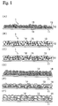
- an electrode structure 1 comprises a layer of electrode material 13 (an electrode material layer 12) on a conductive material such as aluminum or copper.
- the electrode material 13 can deliver and receive electricity to and from ions and has electric attracting power.
- the electrode material 13 is used as a positive electrode structure of a battery using particulate material comprising bonded particles of powdery electrode active material such as LiCoO 2 .
- the electrode material 13 is used as a negative electrode structure of a battery and uses particulate material of powdery electrode active material, such as graphite, hard carbon, etc.,.
- the electrode material 13 uses particulate material such as activated carbon, i.e. a powdery high surface area material with a larger surface area, and is used as an electrode structure 1 of an electrical double layer capacitor.
- the electrode material layer 12 is formed on one surface of a current collector 11, alternatively the electrode material layer 12 may be provided on both surfaces.
- the powdery electrode material 13 of Fig. 1 (A) is covered with an ion conductive polymer, and is used as the positive electrode structure of a battery.
- the powdery electrode material 13 of Fig. 1 (B) is covered with an ion conductive polymer, and is used as the negative electrode structure of a battery.
- the powdery electrode material 13 of Fig. 1 (C) is covered with the ion conductive polymer, and is used as an electrode structure 1 of an electrical double layer capacitor.
- Fig. 2 shows a process in which to produce the electrode structure 1 of Fig. 1 (D).
- the powdery electrode material 13 comprises bonding particles such as LiCoO 2 , where it is covered with an ion conductive polymer 16 and is attached to a current collector 11.
- the electrode structure 1 as shown in Fig. 1 (E) and Fig. 1 (F) can also be produced in a similar manner.
- the conductive material 14 arranged in the electrode structure enhances electrical conductivity between the electrode materials 13 and between the electrode material 13 and the current collector 11 as well as improves the current collecting efficiency.
- adhere or “adhesion” means that ions are attached in such a manner that the ions can migrate between the ion conductive polymer 16 and the entire surface of the powdery electrode material 13. It means that the ion conductive polymer 16 adheres to the surface of the powdery electrode material 13 and covers it with the ion conductive polymer 16. The finer the particles, the more active the powdery electrode material 13. When it is adhered to and covered by the ion conductive polymer 16, the activity is suppressed and can be turned into a more stable state.
- the adhered layer of the ion conductive polymer 16 is thick, electrical conductivity is decreased, and this leads to a lower current collecting efficiency. Therefore, it would be better to form a thinner polymer layer.
- powdery in the powdery electrode material 13 and the powdery conductive material 14 means a material in a fine powder state. In some cases, it means a condition where many fine powdery materials are accumulated.
- the electrode structure 1 is obtained by forming the electrode material layer 12 on the current collector 11.
- the electrode material layer 12 contains the electrode material 13, and comprises a conductive material 14 or a binder 15 when necessary.
- the electrode material 13 is an electrode active material used as an electrode of a battery or a high surface area material used as an electrode for an electrical double layer capacitor.
- the electrode active material means a powdery electrode active material for positive electrode such as LiCoO 2 to be used as a positive electrode, or a powdery electrode active material for negative electrode such as carbon material to be used as a negative electrode.
- a material where ions can be placed into or removed from, or a ⁇ -conjugate conductive macromolecular material may be used as the electrode active material.
- the electrode active material that can be used as a positive electrode of a nonaqueous electrolyte battery, but in case of a chargeable secondary battery, a chalcogen compound where lithium ions can be placed into or removed from, or a complex chalcogen compound containing lithium may be used.
- the chalcogen compound as described above may include FeS 2 , TiS 2 , MoS 2 , V 2 O 5 , V 6 O 12 , MnO 2 , etc.
- the complex chalcogen compound containing lithium as described above, may include LiCoO 2 , lithium complex oxide expressed by Li x Ni y M 1-y O 2 (where M represents at least one type of metal element selected from transition metal or aluminum, or more preferably, it represents at least one type of metal element selected from Co, Mn, Ti, Cr, V, or Al, and 0.05 ⁇ x ⁇ 1.10 and 0.5 ⁇ y ⁇ 1.0), LiNiO 2 , LiMnO 2 , LiMn 2 O 4 , etc.
- oxide, salt or hydroxide of lithium, cobalt, nickel or manganese as starting materials; mixing the starting materials in adequate composition;and firing the mixture in the temperature range of 600°C - 1000°C under an oxygen atmosphere.
- a proper electrode active material to be used as a negative electrode of a nonaqueous electrolyte battery there is no specific restriction. Any material where lithium ions can be placed into or removed from may be used. Examples of such include but are not limited to; Lithium metal, lithium alloy (an alloy of lithium with aluminum, lead, or indium), carbonaceous material, etc.
- the following compounds may be used: polyacetylene, polyaniline, polypyrrole, polythiophene, poly- ⁇ (para)-phenylene, polycarbazole, polyacene, sulfur polymer, etc.
- the ⁇ -conjugate conductive macromolecular material is not limited to those compounds listed above.
- the nonaqueous electrolyte secondary battery excellent cycle service life can be attained if a carbon material where lithium ions can be placed into and removed from is used as the negative electrode.
- a carbon material where lithium ions can be placed into and removed from is used as the negative electrode.
- the carbon material there is no specific restriction on the carbon material, and the following materials may be used: thermally decomposed carbons, cokes (pitch cokes, needle cokes, petroleum cokes, etc.), graphite, vitreous carbons, organic macromolecular compound fired product (product obtained by firing and carbonizing phenol resin, furane resin, etc. at adequate temperature), carbon fiber, activated carbon, etc.
- the electrode material with a larger surface area is a powdery high surface area material, which can attract many ions to the surface.
- it has a specific surface area of 500 m 2 /g or more, or more preferably 1000 m 2 /g or more, or most preferably 1500 m 2 /g - 3000 m 2 /g.
- it has average particle size of 30 ⁇ m or less, or more preferably 5 - 30 ⁇ m. If the specific surface area and the average particle size outside the above ranges, capacitance is too high; thus, it may be difficult to obtain an electrical double layer capacitor with low resistance.
- an activated carbon which can be obtained from carbon material by a steam activation method or by a melted KOH activation process.
- Adequate activated carbons include: coconut shell activated carbon, phenol type activated carbon, petroleum cokes type activated carbon, polyacene, etc.. These materials can be used alone or in a combination of two types or more. Above all, it is preferable to use phenol type activated carbon, petroleum cokes type activated carbon, or polyacene.
- the conductive material is used to increase electrical conductivity of the electrode structure, and there is no specific restriction.
- metal powder, carbon black, ketchen black, acetylene black, carbon whisker, natural graphite, artificial graphite, metal fiber, titanium oxide, ruthenium oxide, etc. may all used as well as other metal powders. These materials may be used alone or in any combination of two types or more. Above all, it is preferable to use one type of carbon black, i.e. ketchen black or acetylene black.
- the average particle size of the powdery conductive material is preferably 10 - 100 nm, or more preferably 20 - 40 nm.
- any material normally used for electrochemical product may be used as the ion conductive salt, as there is no specific restriction.
- a salt obtained by combination of quaternary onium cation expressed by the general formulas R 1 R 2 R 3 R 4 N + or R 1 R 2 R 3 R 4 P + (where R 1 - R 4 each represents an alkyl group having 1 - 10 carbon atoms and may be the same or different) with anion such as BF 4 + , N(CF 3 SO 2 ) 2 - , PF 3 - , ClO 4 - , etc.
- ion conductive salt used may be used for a capacitor: (C 2 H 5 ) 4 PBF 4 , (C 3 H 7 ) 4 PBF 4 , (C 4 H 9 ) 4 PBF 4 , (C 5 H 13 ) 4 PBF 4 , (C 4 H 9 ) 3 CH 2 PBF 4 , (C 2 H 5 ) 3 (Ph-CH 2 )PBF 4 (where Ph represents a phenyl group), (C 2 H 5 ) 4 PPF 4 , (C 2 H 6 )PCF 3 SO 2 , (C 2 H 5 ) 4 NBF 4 , (C 4 H 9 ) 4 NBF 4 , (C 5 H 13 ) 4 NBF 4 , (C 2 H 6 ) 4 NPF 4 , LiBF 4 , LiCF 3 SO 2 , CH 3 (C 2 H 5 ) 3 NBF 4 , etc. These materials may be used alone or in a combination of two types or more.
- any material normally used for electrochemical product may also be used, and there being no specific restriction.
- chain ethers such as dibutyl ether, 1,2-dimethoxyethane, 1,2-ethoxymethoxyethane, methyldiglyme, methyltriglyme, methyltetraglyme, ethylglyme, ethyldiglyme, butyldiglyme, etc.
- glycol ethers such as ethyl cellosolve, ethyl carbitol, butyl cellosolve, butyl carbitol, etc.
- heterocyclic ethers such as tetrahydrofurane, 2-methyl tetrahydrofurane, 1,3-dioxolan, 4,4-dimethyl-1,3-dioxan, etc.
- butyrolactones such as ⁇ -butyrolactone, ⁇ -valerolactone, ⁇ -valerolactone, 3-methyl-1,3-oxazolidine-2
- the ion conductive polymer is a polymer, which can dissolve at least an ion conductive salt such as lithium salt at a concentration of 0.1 M (mol/l) or more, shows an electrical conductivity of 10 -8 S (siemens)/cm or more at room temperature.
- it is an ion conductive polymer, which dissolves at least ion conductive salt such as lithium salt and exhibits electrical conductivity of 10 -3 S/cm - 10 -5 S/cm at room temperature.
- any one type or more of lithium salts containing ClO 4 - , CF 2 SO 3 - , BF 4 - , PF 6 - , AsF 6 - , SbF 6 - , CF 3 CO 2 - , (CF 3 SO 2 ) 2 N - , etc. as an anion may be used.
- the material for forming the ion conductive polymer is a material for preparing ion conductive polymer layer 2 to be formed on the electrode structure 1 or an ion conductive polymer, which is adhered to powdery electrode material. It represents an ion conductive polymer itself, an ion conductive polymer raw material, or both.
- a coating material 22 for forming the ion conductive polymer is a material to be coated for forming the ion conductive polymer layer, and it is a mixture of the material for forming ion conductive polymer itself or ion conductive salt or solvent.
- the ion conductive polymer raw material is a material, which is turned into an ion conductive polymer by polymerization, crosslinking, etc. when energy is added from outside.
- the energy to be added may be heat, ultraviolet ray, light, electronic beam, etc.
- the ion conductive polymer raw material is added to give physical strength such as form retaining property.
- the ion conductive polymer obtained from the ion conductive polymer itself and ion conductive polymer raw material is such that a polymer dissolving lithium salt at concentrations of 0.1 M or more shows electrical conductivity of 10 -6 S (siemens)/cm or more, or more preferably 10 -5 S/cm or more, or most preferably 10 -1 S/cm or more at room temperature.
- a cellulose type semi-interpenetrating network system is described in JP-A-8-225626
- PVA type semi-interpenetrating network system is disclosed in Japanese Patent Application 11-78087 (PCT/JP 00/01734)
- polyglycidol semi-interpenetrating network system is disclosed in Japanese Patent Application 10-358825 (PCT/JP 99/07039)
- polyurethane type semi-interpenetrating network system is disclosed in Japanese Patent Application 11-78085 (PCT/JP 00/01731).
- the current collector 11 may be any material which allows an electric current to pass. Its shape and material are selected depending upon each electrical component. As an example, a conductive material such as aluminum, copper, etc. is formed in planar shape, or in form of foil or mesh. The surface is processed by either a chemical, an electrical or a physical process or by a combination of these processes; surface irregularities and a coarse surface are formed to provide a current collector with better adhesion properties. In case of a current collector 11 in a planar shape or foil, one surface or both surfaces are used depending on the structure of the electrical component, the electrode material is attached on one surface or both surfaces.
- the accommodation unit 4 of the electrical component is a container to accommodate an element member 3, which comprises a pair of electrode structures.
- This may be any container commonly used in the past, and comes in various forms.
- an external material of a battery serving as the accommodation unit 4 includes a metal case made of aluminum or stainless steel, or pouch type or pill package type or pillow case type made of aluminum laminated plastic film.
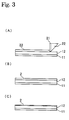
- a coating material 22 for forming a paste-like ion conductive polymer layer to serve as the ion conductive polymer layer 2 is thinly coated on the surface of the electrode material layer 12 of the electrode structure 1 as shown in Fig. 3 using a doctor knife applicator 21 (Fig. 3 (A)), resulting in an ion conductive polymer layer 2 being formed on the electrode structure 1 (Fig. 3 (B)).
- the coating material 22 for forming the ion conductive polymer layer is a material for forming the ion conductive polymer layer 2 by coating, and it is the ion conductive polymer forming material or a mixture of this with ion conductive salt such as lithium salt or a solvent.
- the coating material 22 for forming ion conductive polymer layer which is a mixture of ion conductive polymer forming material with organic solvent, it is dried after coating, and then the solvent is purged from the ion conductive polymer layer 2 (Fig. 3 (C)).
- ion conductive polymer layer mixed with ion conductive salt such as lithium salt is coated on the ion conductive polymer forming material, ions such as lithium ions, are dissolved in the ion conductive polymer layer 2.
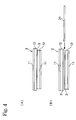
- the ion conductive polymer layer 2 is formed at least on one of a pair of the electrode structures 1. For instance, as shown in Fig. 4, a pair of the electrode structures 1 are arranged at opposed positions, and an element member 3 is fabricated (Fig. 4 (A)). Or, the ion conductive polymer layer 2 is formed on both pairs of the electrode structures 1, and these may be used as the element member 3. Or rather, between a pair of the electrode structures 1 where the ion conductive polymer layer 2 is formed on one or both of the pair, a separator 31 may be arranged, and this may be used as the element member 3 of the electrode structures 1 (Fig. 4 (B)).
- separator Any type of separator may be used that have insulating properties and allow ions to pass.
- polyethylene nonwoven fabric porous film, polypropylene nonwoven fabric porous film, polyester nonwoven fabric polymer porous film, PTFE porous film, craft paper, rayon fiber, saisal fiber mixed sheet, Manila hemp sheet, glass fiber sheet, cellulose type electrolytic paper, paper made of rayon fiber, mixed paper made of cellulose and glass fiber, or any of these materials are combined in two or more layers and are used.
- a pair of electrode structures arranged at opposed positions, i.e. the element members 3, are accommodated in the accommodation unit 4 as shown in Fig. 5.
- There are various methods to facilitate such accommodation For instance, a method to wind up the element member 3 (Fig. 5 (B)), a method to fold the element member 3 (Fig. 5 (C)), or a method to overlap a plurality of element members 3 (Fig. 5 (D)) may all be used.
- liquid electrolyte When liquid electrolyte is injected into the accommodation unit 4, the liquid electrolyte permeates into the ion conductive polymer layer 12 of the element member 3, and the ion conductive polymer layer 12 swells. Also, the liquid electrolyte permeates into gaps in the electrode material layer or penetrates into the ion conductive polymer itself, which is adhered to the powdery electrode material.
- the ion conductive polymer itself or the ion conductive polymer raw material is put into the liquid electrolyte.
- total ion concentration may be decreased.
- ion conductive salt is put into it. It is preferable that (concentration of ion conductive salt in the ion conductive polymer) > (concentration of ion conductive salt in the liquid electrolyte) because liquid electrolyte rapidly permeates into the ion conductive polymer layer 12 by osmotic pressure.
- the liquid electrolyte enters the ion conductive polymer layer 12 with a higher concentration because of osmotic pressure.
- the ion conductive polymer raw material permeates together with the liquid electrolyte into the ion conductive polymer layer or into the electrode material layer. Then, it reacts when heated, and is turned into 3-dimentional network. As a result, the electrode structures at opposed positions are integrated with the polymer layer.
- Example 1 Coating of the coating material for forming ion conductive polymer layer on positive electrode structure of the battery
- lithium perchlorate was to be 1 mol per 1 kg of the total weight of the mixture of lithium perchlorate + cyanoethylated dihydroxypropyl cellulose + polyethylene glycol dimethacrylate + methoxypolyethylene glycol monomethacrylate + azobis-isobutyronitrile, and the coating material 22 for forming the ion conductive polymer layer of the complex product of polymer electrolyte - lithium perchlorate was prepared.
- the coating material 22 for forming the ion conductive polymer layer of the polymer electrolyte - lithium perchlorate complex product thus prepared was cast on a positive electrode structure (the electrode structure 1 prepared by coating the positive electrode material on the current collector) using a doctor knife applicator. It was left to stand at 80°C for 0.5 hour, and an ion conductive solid macromolecular electrolyte film layer in semi-solid state (ion conductive polymer layer 2) resulted.
- the electrode material of the negative electrode structure was overlapped at an opposite position on the film layer (ion conductive polymer layer 2) relative to the positive electrode structure. This was left to stand at 80°C for one hour, and the element member 3 resulted.
- Example 2 Coating of the coating material for forming ion conductive polymer layer on both of positive electrode structure and negative electrode structure
- Example 2 On the negative electrode structure, the complex product of polymer electrolyte - lithium perchlorate (coating material 22 for forming ion conductive polymer layer) prepared in Example 1 was cast using an applicator. This was left to stand at 80°C for 0.5 hour, and ion conductive solid macromolecular electrolyte film layer in semi-solid state (ion conductive polymer layer 2) was formed, and a negative electrode structure with the ion conductive polymer layer 2 was prepared. Then, the same procedure as in Example 1 was performed except that the negative electrode structure was used. Positive and negative electrode structures were arranged at opposed positions with the sides of the ion conductive polymer layers facing to each other, and the element member 3 resulted.
- Example 3 Coating of the coating material for forming ion conductive polymer layer on both of positive electrode structure and negative electrode structure with a separator between them
- Example 2 The complex product of polymer electrolyte - lithium perchlorate as prepared in Example 1 was cast on the positive electrode structure and the negative electrode structure using an applicator.
- the positive electrode structure and the negative electrode structure were arranged at opposed positions via a separator 31. This was left to stand at 80°C for one hour, and an element member 3 resulted.
- Example 4 - 6 the complex product of polymer electrolyte - lithium perchlorate (coating material 22 for forming ion conductive polymer layer) thus prepared was used in the same manner as in Examples 1 - 3 instead of the complex product of polymer electrolyte - lithium perchlorate used in Examples 4 - 6. After casting, this was left to stand at 80°C for 3 hours to evaporate the tetrahydrofurane. Thus, ion conductive solid macromolecular electrolyte film layer (ion conductive polymer layer 2) in thin film and semi-solid state was prepared.
- the complex product of polymer electrolyte - lithium perchlorate (coating material 22 for forming ion conductive polymer layer) was prepared.
- the complex product thus prepared was a viscous solution.
- Example 7 - 9 the complex product of polymer electrolyte - lithium perchlorate as prepared in this case (coating material 22 for forming ion conductive polymer layer) was used instead of the complex product of polymer electrolyte - lithium perchlorate used in Examples 1 - 3.
- the other procedure used was the same as described above.
- Example 10 - 12 the complex product of polymer electrolyte - lithium perchlorate (coating material 22 for forming ion conductive polymer layer) as prepared was used instead of the complex product of polymer electrolyte - lithium perchlorate used in the same manner as in Examples 7 - 9. After coating, it was left to stand at 80°C for 3 hours to evaporate the tetrahydrofurane. Thus, ion conductive solid macromolecular electrolyte film layer (ion conductive polymer layer 2) in thin film and semi-solid state was prepared. The other procedure was the same as described above.
- the element member 3 obtained in Example 1 was cut in size of 3 ⁇ 3 cm (length ⁇ width), and tab was attached, and a single layer battery was prepared. This was placed in the external case. Then, it was sealed, and the battery was heated to 80°C, and charging and discharging were performed. As a result, it was confirmed that the battery operated as an all-solid type battery.
- the coating material 22 for forming the ion conductive polymer as obtained in Example 1 was cast using an applicator on a glass plate, which was thinly coated with a silicon mold releasing agent. The thickness was 100 ⁇ m. The glass plate with silicon mold releasing agent was placed with a spacer of 100 ⁇ m and was sandwiched. It was left to stand at 80°C for one hour to react.
- the polymer electrolyte film thus obtained contained liquid electrolyte of 1 mol/kg.
- the film thus obtained was immersed into the solution of Example 13 (liquid electrolyte A) containing perchlorate solution of 0.5 mol, 0.7 mol and 1 mol respectively, and volume swellability was determined. The results are summarized in Table 1.
- ion conductive polymer or ion conductive polymer raw material or a mixture of these i.e. the material for forming ion conductive polymer
- a solvent is added to turn it into a liquid and paste-like state. This is coated on a current collector and is dried to evaporate the solvent. Or, the solvent may be added from the beginning, and it may be turned to paste-like state at the same time as it is adhered to the ion conductive polymer forming material.
- the ion conductive polymer forming material and the powdery electrode material are pressurized and ground against each other, and a pressurized product is obtained.
- Pressurizing and grinding is defined as an operation to grind a mixture 50 of the ion conductive polymer forming material and the powdery electrode material 13 against each other while pressurizing. External force is applied on the mixture 50 to make the mixture 50 pressed tightly. When the particles are rotated and this procedure is repeated, a pressurized product is obtained.
- a pressurizing, grinding and kneading device 5 is as shown in Fig. 6.
- the mixture 50 of the ion conductive polymer forming material and the powdery electrode material 13, or a mixture 50 containing this mixture and solvent, is placed in a container 51, and a main blade 52 is rotated. There is a gap between a bottom 511 of the container 51 and the main blade 52.
- a part of the mixture 10 is moved between the bottom 211 of the container and the main blade 22. It is pressurized and ground against each other and kneaded. This procedure is repeated, and the ion conductive polymer forming material is adhered to the powdery electrode material 13.
- a dispersing blade 53 is provided in the container 51. By rotating the dispersing blade 53 at high speed, the mixture 50 pressurized and ground is dispersed.
- the mixture 50 is pressurized and ground against each other in the container 51, and the container accommodates the mixture 50 to agitate.
- a lower portion 5111 With a part of it at lower position.
- the bottom surface is inclined upward as it goes toward the peripheral portion. For instance, it is lower at the center, and it gradually goes up toward the periphery. It is formed in a bottom 511 in the shape of the conical mortar.
- the inclination angle of the lower portion 5111 is set to 120°C, for example.
- the bottom 511 of the container has wear resistant property. It is made of SUS, for instance, and spraying tungsten or carbide forms it.
- a plurality of the lower portions 5111 may be provided at the bottom surface.
- the main blade 52 cooperates with the bottom surface of the container 51 to pressurize, grind and agitate the mixture.
- the main blade 52 has its shaft mounted in a position corresponding to the lower portion 5111 of the container 51, and is bent upward along the bottom of the container from the lower portion 5111.
- two blades of the main blade 52 are mounted from the central portion. There may be two or more blades, and the number of blades is determined depending on the quantity and the type of the mixture.
- the number of revolutions of a main motor 522 for driving a main shaft 521 of the main blade is at low speed during pressurizing and grinding operation. It is set, for instance, to 120 rpm or lower.
- the gap between the bottom surface of the container 51 and the bottom surface of the main blade 52 is designed so narrow that the mixture can be pressurized and ground against each other.
- This gap is set to 15 mm or less, for example.
- the distance of the gap depends upon the capacity of the pressurizing, grinding and kneading device or on the shape of the main blade.
- the surface of the main blade 52 in advancing direction is set in such manner that pressurizing angle ⁇ with respect to the bottom surface of the container 51 will be an acute angle.
- pressurizing angle ⁇ is set to 3° - 70° .
- the cross-section of the main blade 52 may be in circular or rectangular shape with a rounded corner as shown in Fig. 6 (D).
- the material of the main blade must be wear-resistant. For instance, SUS should be used, and it is formed by spraying tungsten or carbide.
- the surface of the main blade 52 opposite to the advancing direction is designed in such manner that it runs almost perpendicularly to the bottom surface and at acute angle.
- the central portion of the main blade 52 is also arranged at the positions corresponding to the number of the lower portions.
- the dispersing blade 53 is to disperse the mixture 50, which is pressurized and ground by the main blade 52.
- the dispersing blade 53 is arranged at such position as to disperse the mixture 50, and it is rotated at high speed, i.e. at 1000 - 4000 rpm. By rotating it at high speed, the ion conductive polymer 16 or its raw material adhered on the surface of the particles of the powdery electrode material 13 are evenly dispersed over the entire powdery material.
- the pressurized product which was pressurized and ground and was turned into paste-like state, is thinly coated on the surface of the current collector. After coating, the solvent is evaporated, and the product is dried, and an electrode structure is obtained. As the device to coat the pressurized product on the current collector, an applicator is used.
- the pressurized product thus coated may be pressed against the current collector to tightly fix it.
- a tightly fixing device 6 as shown in Fig. 7 is used.
- an electrode structure 1 comprising the current collector coated with the pressurized product is sandwiched between pressure rollers 61.
- a backup roller 62 is rotated under pressure between the pressure device 63 and a fixed member 64.
- the pressurized product is tightly fixed on the current collector, and the electrode structure 1 can be produced.
- a pressurizing, grinding and kneading device Into a pressurizing, grinding and kneading device, 9.1 weight parts of LiCoO 2 with average particle size of 5 ⁇ m, i.e. powdery electrode active material, and 0.6 weight part of graphite powder with average particle size of 4 ⁇ m, i.e. powdery conductive material, are placed, and the mixture was pressurized and ground for 20 minutes. Then, 0.546 weight part of an ion conductive polymer raw material (A1) and 3.5 weight parts of acetonitrile were added.
- the ion conductive polymer raw material (A1) is a mixture, and its composition and mixing ratio are as shown in Table 2.
- the pressurized product added with the ion conductive polymer raw material (A1) was pressurized and ground for 5 hours in the pressurizing, grinding and kneading device.
- the pressurized product was turned into a paste-like state.
- 0.254 weight part of polymeric MDI MR-220; manufactured by NPU
- the pressurized product was taken out and was placed on an aluminum foil of 20 ⁇ m in thickness, and it was cast using an applicator with gap of 100 ⁇ m. It was left to stand at room temperature for 15 minutes. Then, it was heated at 80°C for one hour.
- the positive electrode structure thus prepared had thickness of 80 ⁇ m.
- the pressurized product was removed, and this was placed on an aluminum foil of 20 ⁇ m in thickness and was cast using an applicator with a gap of 100 ⁇ m. Then, this was left to stand at room temperature for 15 minutes and was then heated at 80°C for one hour. The electrode thus obtained had thickness of 80 ⁇ m.
- a pressurizing, grinding and kneading device (volume capacity: 300 cc)
- 2.0 weight parts of ion conductive polymer raw material (A2) and 3.0 weight parts of acetonitrile were added.
- the ion conductive polymer raw material (A2) is a mixture, and its composition and mixing ratio are as shown in Table 3.
- Ion conductive polymer raw material (A2) Substance Mixing ratio (weight parts) Cyanoethylated dihydroxypropylated polyvinyl alcohol 0.625 Methoxypolyethylene glycol methacrylate (Mw: 468) 3.125 Trimethylolpropane trimethacrylate 6.25 Total 10
- the pressurized product added with the ion conductive polymer raw material (A2) was pressurized and ground for 5 hours in a pressurizing, grinding and kneading device (volume capacity: 300 cc).
- the pressurized product was turned into a paste-like state.
- the pressurized product was removed and placed on an aluminum foil of 20 ⁇ m in thickness and was cast using an applicator with gap of 100 ⁇ m. This was left to stand at room temperature for 15 minutes and was then heated at 80°C for 3 hours.
- the electrode thus obtained had a thickness of 80 ⁇ m.
- the pressurized product was removed and was placed on a copper foil of 20 ⁇ m in thickness and was cast using an applicator with gap of 100 ⁇ m. This was left to stand at room temperature for 15 minutes and was then heated at 80°C for one hour. The electrode thus obtained had a thickness of 80 ⁇ m.
- an electrode for capacitor carbon black was added as powdery conductive material to phenol derived activated carbon (manufactured by Kansai Chemical Co., Ltd.) as electrode material. This was processed by dry mixing using a mixer. Then, polymer A1 was added as a binder and was mixed. Further, NMP (N-methylpyrrolidone) was added as solvent and was mixed. After mixing, this was cast on a current collector using a doctor knife applicator. The specimen was dried under infrared light or hot air. The thickness of the electrode thus prepared was 75 ⁇ m.
Landscapes
- Chemical & Material Sciences (AREA)
- Engineering & Computer Science (AREA)
- Chemical Kinetics & Catalysis (AREA)
- Electrochemistry (AREA)
- General Chemical & Material Sciences (AREA)
- Power Engineering (AREA)
- Manufacturing & Machinery (AREA)
- Microelectronics & Electronic Packaging (AREA)
- Inorganic Chemistry (AREA)
- Materials Engineering (AREA)
- Condensed Matter Physics & Semiconductors (AREA)
- General Physics & Mathematics (AREA)
- Physics & Mathematics (AREA)
- Dispersion Chemistry (AREA)
- Crystallography & Structural Chemistry (AREA)
- Secondary Cells (AREA)
- Battery Electrode And Active Subsutance (AREA)
- Electric Double-Layer Capacitors Or The Like (AREA)
Applications Claiming Priority (3)
| Application Number | Priority Date | Filing Date | Title |
|---|---|---|---|
| JP2000141687A JP2001325991A (ja) | 2000-05-15 | 2000-05-15 | 電気部品及びその製造方法 |
| JP2000141687 | 2000-05-15 | ||
| EP01111816A EP1156547A1 (fr) | 2000-05-15 | 2001-05-15 | Procédé de préparation d'une pile ou d'un condensateur présentant un électrolyte à base de gel polymère |
Related Parent Applications (1)
| Application Number | Title | Priority Date | Filing Date |
|---|---|---|---|
| EP01111816A Division EP1156547A1 (fr) | 2000-05-15 | 2001-05-15 | Procédé de préparation d'une pile ou d'un condensateur présentant un électrolyte à base de gel polymère |
Publications (1)
| Publication Number | Publication Date |
|---|---|
| EP1300904A1 true EP1300904A1 (fr) | 2003-04-09 |
Family
ID=18648769
Family Applications (2)
| Application Number | Title | Priority Date | Filing Date |
|---|---|---|---|
| EP01111816A Withdrawn EP1156547A1 (fr) | 2000-05-15 | 2001-05-15 | Procédé de préparation d'une pile ou d'un condensateur présentant un électrolyte à base de gel polymère |
| EP03000421A Withdrawn EP1300904A1 (fr) | 2000-05-15 | 2001-05-15 | Pile ou condensateur électrique à double couche à électolyte gel polymère et son procédé de fabrication |
Family Applications Before (1)
| Application Number | Title | Priority Date | Filing Date |
|---|---|---|---|
| EP01111816A Withdrawn EP1156547A1 (fr) | 2000-05-15 | 2001-05-15 | Procédé de préparation d'une pile ou d'un condensateur présentant un électrolyte à base de gel polymère |
Country Status (8)
| Country | Link |
|---|---|
| US (2) | US6793692B2 (fr) |
| EP (2) | EP1156547A1 (fr) |
| JP (1) | JP2001325991A (fr) |
| KR (1) | KR20010104682A (fr) |
| CN (1) | CN1248334C (fr) |
| CA (1) | CA2347408A1 (fr) |
| SG (1) | SG100695A1 (fr) |
| TW (1) | TW512556B (fr) |
Cited By (2)
| Publication number | Priority date | Publication date | Assignee | Title |
|---|---|---|---|---|
| WO2005013299A1 (fr) | 2003-07-07 | 2005-02-10 | Eamex Corporation | Condensateur et procede de fabrication de ce dernier |
| CN109148818A (zh) * | 2018-08-28 | 2019-01-04 | 江苏双登富朗特新能源有限公司 | 用于全固态锂电池的聚氧化乙烯溶液注装工艺 |
Families Citing this family (34)
| Publication number | Priority date | Publication date | Assignee | Title |
|---|---|---|---|---|
| DE10231949B4 (de) * | 2002-07-15 | 2007-05-16 | Dilo Trading Ag | Lithium-Polymer Batterie und Verfahren zur Herstellung von Lithium-Polymer Batterien |
| JP4194332B2 (ja) * | 2002-09-30 | 2008-12-10 | 三洋電機株式会社 | リチウム電池 |
| US20040151951A1 (en) * | 2002-12-17 | 2004-08-05 | The University Of Chicago | Lithium based electrochemical cell systems |
| FR2852148B1 (fr) * | 2003-03-07 | 2014-04-11 | Batscap Sa | Materiau pour electrode composite, procede pour sa preparation |
| US7399322B2 (en) * | 2003-07-08 | 2008-07-15 | Bps Co., Ltd | Method of making porous polymeric separator and lithium ion polymer battery |
| JP4449447B2 (ja) * | 2003-12-22 | 2010-04-14 | 日産自動車株式会社 | 固体電解質電池の製造方法 |
| CN100527519C (zh) * | 2004-09-03 | 2009-08-12 | 松下电器产业株式会社 | 非水电解液及含有该非水电解液的二次电池 |
| JP4986426B2 (ja) * | 2004-09-03 | 2012-07-25 | パナソニック株式会社 | 非水電解液二次電池用非水電解液およびこれを含む二次電池 |
| DE102005043829A1 (de) | 2005-09-13 | 2007-04-05 | H.C. Starck Gmbh | Verfahren zur Herstellung von Elektrolytkondensatoren mit hoher Nennspannung |
| DE102005043828A1 (de) | 2005-09-13 | 2007-03-22 | H.C. Starck Gmbh | Verfahren zur Herstellung von Elektrolytkondensatoren |
| KR101002800B1 (ko) * | 2006-06-09 | 2010-12-21 | 삼성전자주식회사 | 무선 이동 통신 시스템에서 공통 제어 정보 송신 방법 |
| US7830646B2 (en) * | 2007-09-25 | 2010-11-09 | Ioxus, Inc. | Multi electrode series connected arrangement supercapacitor |
| US20090279230A1 (en) * | 2008-05-08 | 2009-11-12 | Renewable Energy Development, Inc. | Electrode structure for the manufacture of an electric double layer capacitor |
| US8411413B2 (en) | 2008-08-28 | 2013-04-02 | Ioxus, Inc. | High voltage EDLC cell and method for the manufacture thereof |
| CN103098159A (zh) * | 2010-08-12 | 2013-05-08 | 麻省理工学院 | 柔性导电聚合物能量存储装置 |
| US9520243B2 (en) * | 2014-02-17 | 2016-12-13 | Korea Institute Of Energy Research | Method of manufacturing flexible thin-film typer super-capacitor device using a hot-melt adhesive film, and super-capacitor device manufactured by the method |
| US9666898B2 (en) | 2014-07-22 | 2017-05-30 | John E. Stauffer | Storage battery using a uniform mix of conductive and nonconductive granules in a lithium bromide electrolyte |
| US9509017B2 (en) * | 2014-07-22 | 2016-11-29 | John E. Stauffer | Lithium storage battery |
| CN109690827A (zh) | 2016-09-22 | 2019-04-26 | 苹果公司 | 用于叠堆电池设计的集电器 |
| WO2018195372A1 (fr) | 2017-04-21 | 2018-10-25 | Cougeller Research Llc | Cellule de batterie avec matériau de diffusion d'électrolyte |
| WO2018213601A2 (fr) | 2017-05-19 | 2018-11-22 | Cougeller Research Llc | Batterie rechargeable avec polymère conducteur d'anions |
| US11862801B1 (en) | 2017-09-14 | 2024-01-02 | Apple Inc. | Metallized current collector for stacked battery |
| WO2019055893A1 (fr) * | 2017-09-18 | 2019-03-21 | Avx Corporation | Ultracondensateur à faible courant de fuite |
| US11335977B1 (en) | 2017-09-21 | 2022-05-17 | Apple Inc. | Inter-cell connection materials |
| US11043703B1 (en) | 2017-09-28 | 2021-06-22 | Apple Inc. | Stacked battery components and configurations |
| CN110534696B (zh) * | 2019-07-29 | 2022-08-16 | 深圳大学 | 一种柔性电池及其制备方法 |
| CN110600268A (zh) * | 2019-08-14 | 2019-12-20 | 益阳艾华富贤电子有限公司 | 一种定量注入电解液的固液混合电容器制作方法 |
| CN111653430B (zh) * | 2020-04-28 | 2021-10-08 | 安徽诚越电子科技有限公司 | 一种高闪火电压高电导率铝电解电容器用电解液以及铝电解电容器 |
| US11923494B2 (en) | 2020-09-08 | 2024-03-05 | Apple Inc. | Battery configurations having through-pack fasteners |
| US11600891B1 (en) | 2020-09-08 | 2023-03-07 | Apple Inc. | Battery configurations having balanced current collectors |
| US11677120B2 (en) | 2020-09-08 | 2023-06-13 | Apple Inc. | Battery configurations having through-pack fasteners |
| US11588155B1 (en) | 2020-09-08 | 2023-02-21 | Apple Inc. | Battery configurations for cell balancing |
| CN114552123B (zh) * | 2022-01-17 | 2024-01-30 | 上海兰钧新能源科技有限公司 | 一种锂离子电池隔离膜、电芯及锂离子电池 |
| JP2023170689A (ja) * | 2022-05-19 | 2023-12-01 | 株式会社マテリアルイノベーションつくば | 電極材料、電極及びキャパシタ |
Citations (5)
| Publication number | Priority date | Publication date | Assignee | Title |
|---|---|---|---|---|
| JPH08225626A (ja) * | 1994-11-22 | 1996-09-03 | Nisshinbo Ind Inc | イオン導電性高分子固体電解質、組成物及び製造方法 |
| WO1999049531A1 (fr) * | 1998-03-23 | 1999-09-30 | Koninklijke Philips Electronics N.V. | Electrolyte a base de gel polymerique |
| EP0971433A1 (fr) * | 1998-01-27 | 2000-01-12 | Yuasa Corporation | Pile secondaire au lithium de type plat |
| DE19830993A1 (de) * | 1998-07-10 | 2000-01-13 | Basf Ag | Polymerer Gelektrolyt und Verfahren zu seiner Herstellung |
| WO2000013252A1 (fr) * | 1998-09-01 | 2000-03-09 | Sony Corporation | Procede de production d'un element electrolytique en gel non aqueux |
Family Cites Families (8)
| Publication number | Priority date | Publication date | Assignee | Title |
|---|---|---|---|---|
| JP3203093B2 (ja) * | 1993-03-30 | 2001-08-27 | 三洋電機株式会社 | 固体電解質電池 |
| JP3132281B2 (ja) * | 1994-02-21 | 2001-02-05 | 松下電器産業株式会社 | 非水電解液二次電池の製造方法 |
| JP4355970B2 (ja) * | 1997-10-29 | 2009-11-04 | ソニー株式会社 | 固体電解質電池及びその製造方法 |
| JP3260310B2 (ja) * | 1997-11-04 | 2002-02-25 | ティーディーケイ株式会社 | シート型電極・電解質構造体の製造方法 |
| JP4055234B2 (ja) * | 1998-02-13 | 2008-03-05 | ソニー株式会社 | 固体電解質電池 |
| JPH11288738A (ja) * | 1998-04-01 | 1999-10-19 | Ricoh Co Ltd | 固体電解質電池およびその製造方法 |
| KR20000019372A (ko) * | 1998-09-10 | 2000-04-06 | 박호군 | 균질상의 고체고분자합금 전해질 및 그 제조방법과, 그 전해질을 이용한 복합전극, 리튬고분자전지, 리튬이온고분자전지 및그 제조방법 |
| US6420071B1 (en) * | 2000-03-21 | 2002-07-16 | Midwest Research Institute | Method for improving the durability of ion insertion materials |
-
2000
- 2000-05-15 JP JP2000141687A patent/JP2001325991A/ja active Pending
-
2001
- 2001-05-11 CA CA002347408A patent/CA2347408A1/fr not_active Abandoned
- 2001-05-11 SG SG200102795A patent/SG100695A1/en unknown
- 2001-05-11 US US09/853,050 patent/US6793692B2/en not_active Expired - Fee Related
- 2001-05-15 KR KR1020010026553A patent/KR20010104682A/ko not_active Abandoned
- 2001-05-15 CN CNB011161345A patent/CN1248334C/zh not_active Expired - Fee Related
- 2001-05-15 TW TW090111551A patent/TW512556B/zh not_active IP Right Cessation
- 2001-05-15 EP EP01111816A patent/EP1156547A1/fr not_active Withdrawn
- 2001-05-15 EP EP03000421A patent/EP1300904A1/fr not_active Withdrawn
-
2003
- 2003-06-27 US US10/607,956 patent/US20040001302A1/en not_active Abandoned
Patent Citations (6)
| Publication number | Priority date | Publication date | Assignee | Title |
|---|---|---|---|---|
| JPH08225626A (ja) * | 1994-11-22 | 1996-09-03 | Nisshinbo Ind Inc | イオン導電性高分子固体電解質、組成物及び製造方法 |
| EP0971433A1 (fr) * | 1998-01-27 | 2000-01-12 | Yuasa Corporation | Pile secondaire au lithium de type plat |
| WO1999049531A1 (fr) * | 1998-03-23 | 1999-09-30 | Koninklijke Philips Electronics N.V. | Electrolyte a base de gel polymerique |
| DE19830993A1 (de) * | 1998-07-10 | 2000-01-13 | Basf Ag | Polymerer Gelektrolyt und Verfahren zu seiner Herstellung |
| WO2000013252A1 (fr) * | 1998-09-01 | 2000-03-09 | Sony Corporation | Procede de production d'un element electrolytique en gel non aqueux |
| EP1041658A1 (fr) * | 1998-09-01 | 2000-10-04 | Sony Corporation | Procede de production d'un element electrolytique en gel non aqueux |
Non-Patent Citations (2)
| Title |
|---|
| CLERICUZIO M ET AL: "Ionic diffusivity and conductivity of plasticized polymer electrolytes: PMFG-NMR and complex impedance studies", SOLID STATE IONICS, NORTH HOLLAND PUB. COMPANY. AMSTERDAM, NL, vol. 82, no. 3, 1 December 1995 (1995-12-01), pages 179 - 192, XP004050220, ISSN: 0167-2738 * |
| PATENT ABSTRACTS OF JAPAN vol. 1997, no. 01 31 January 1997 (1997-01-31) * |
Cited By (4)
| Publication number | Priority date | Publication date | Assignee | Title |
|---|---|---|---|---|
| WO2005013299A1 (fr) | 2003-07-07 | 2005-02-10 | Eamex Corporation | Condensateur et procede de fabrication de ce dernier |
| EP1696446A4 (fr) * | 2003-07-07 | 2009-07-22 | Eamex Corp | Condensateur et procede de fabrication de ce dernier |
| CN109148818A (zh) * | 2018-08-28 | 2019-01-04 | 江苏双登富朗特新能源有限公司 | 用于全固态锂电池的聚氧化乙烯溶液注装工艺 |
| CN109148818B (zh) * | 2018-08-28 | 2021-04-13 | 江苏双登富朗特新能源有限公司 | 用于全固态锂电池的聚氧化乙烯溶液注装工艺 |
Also Published As
| Publication number | Publication date |
|---|---|
| CN1324117A (zh) | 2001-11-28 |
| EP1156547A1 (fr) | 2001-11-21 |
| US20020042986A1 (en) | 2002-04-18 |
| US6793692B2 (en) | 2004-09-21 |
| SG100695A1 (en) | 2003-12-26 |
| US20040001302A1 (en) | 2004-01-01 |
| JP2001325991A (ja) | 2001-11-22 |
| TW512556B (en) | 2002-12-01 |
| KR20010104682A (ko) | 2001-11-26 |
| CA2347408A1 (fr) | 2001-11-15 |
| CN1248334C (zh) | 2006-03-29 |
Similar Documents
| Publication | Publication Date | Title |
|---|---|---|
| US6793692B2 (en) | Electrical component and method for manufacturing the same | |
| KR100614579B1 (ko) | 전지용 활성물질 혼합분체, 전지용 전극 조성물, 이차전지용 전극, 이차 전지, 전기 이중층 커패시터용탄소재료 혼합분체, 분극성 전극 조성물, 분극성 전극, 및전기 이중층 커패시터 | |
| US7651820B2 (en) | Gel electrolyte and gel electrolyte battery | |
| US6838211B2 (en) | Pregel compositions for polymer gel electrolytes, method of dehydrating pregel compositions, secondary cell, and electrical double-layer capacitor | |
| EP1548750B1 (fr) | Electrolyte non aqueux, condensateurs double couche, et accumulateurs a electrolyte non aqueux | |
| US7455935B2 (en) | Ion-conductive electrolyte and cell employing the same | |
| EP1548866A1 (fr) | Electrolyte non aqueux et batterie secondaire a electrolyte non aqueux | |
| JP4099637B2 (ja) | 分極性電極組成物及びその製造方法、分極性電極、並びに電気二重層キャパシタ | |
| US20040139587A1 (en) | Polymer gel electrolyte-use composition and method for non-aqueous electrolyte solution | |
| US20040076885A1 (en) | Composition for polymer gel electrolyte, polymer gel electrolyte, and secondary battery and electric double layer capacitor each employing the electrolyte | |
| US6871585B2 (en) | Pressure method for an electrode structure | |
| WO1996038868A1 (fr) | Electrodes composites pour cellules electrochimiques secondaires au lithium a polymere, et cellules dotees de ces electrodes | |
| KR20030051657A (ko) | 리튬 폴리머 이차전지 및 그의 제조방법 | |
| KR100462668B1 (ko) | 폴리머 전지 | |
| JPH0864203A (ja) | 電極、電極の製造方法および該電極を用いた二次電池 | |
| JP2002334683A (ja) | 電気部品、そのパッケージ及びパッケージ方法 | |
| JPH09330740A (ja) | 電気化学セル及び電気化学セルの製造方法 |
Legal Events
| Date | Code | Title | Description |
|---|---|---|---|
| PUAI | Public reference made under article 153(3) epc to a published international application that has entered the european phase |
Free format text: ORIGINAL CODE: 0009012 |
|
| AC | Divisional application: reference to earlier application |
Ref document number: 1156547 Country of ref document: EP Kind code of ref document: P |
|
| AK | Designated contracting states |
Kind code of ref document: A1 Designated state(s): AT BE CH CY DE DK ES FI FR GB GR IE IT LI LU MC NL PT SE TR Designated state(s): AT BE CH CY DE DK ES FI FR GB GR IE IT LI LU MC NL PT SE TR |
|
| AX | Request for extension of the european patent |
Extension state: AL LT LV MK RO |
|
| 17P | Request for examination filed |
Effective date: 20030814 |
|
| 17Q | First examination report despatched |
Effective date: 20031001 |
|
| AKX | Designation fees paid |
Designated state(s): AT BE CH CY DE DK ES FI FR GB GR IE IT LI LU MC NL PT SE TR |
|
| STAA | Information on the status of an ep patent application or granted ep patent |
Free format text: STATUS: THE APPLICATION IS DEEMED TO BE WITHDRAWN |
|
| 18D | Application deemed to be withdrawn |
Effective date: 20040212 |