EP1300928A2 - Kleinmotors und Verfahren zur Herstellung desselben - Google Patents
Kleinmotors und Verfahren zur Herstellung desselben Download PDFInfo
- Publication number
- EP1300928A2 EP1300928A2 EP02022087A EP02022087A EP1300928A2 EP 1300928 A2 EP1300928 A2 EP 1300928A2 EP 02022087 A EP02022087 A EP 02022087A EP 02022087 A EP02022087 A EP 02022087A EP 1300928 A2 EP1300928 A2 EP 1300928A2
- Authority
- EP
- European Patent Office
- Prior art keywords
- case
- metal case
- case cover
- attached
- soldering part
- Prior art date
- Legal status (The legal status is an assumption and is not a legal conclusion. Google has not performed a legal analysis and makes no representation as to the accuracy of the status listed.)
- Granted
Links
- 238000004519 manufacturing process Methods 0.000 title claims description 4
- 239000002184 metal Substances 0.000 claims abstract description 45
- 238000005476 soldering Methods 0.000 claims abstract description 40
- 238000003466 welding Methods 0.000 claims abstract description 11
- 229920003002 synthetic resin Polymers 0.000 claims description 8
- 239000000057 synthetic resin Substances 0.000 claims description 8
- 238000004804 winding Methods 0.000 claims description 7
- 230000003245 working effect Effects 0.000 abstract 1
- 229910000679 solder Inorganic materials 0.000 description 8
- 239000003990 capacitor Substances 0.000 description 6
- 238000000034 method Methods 0.000 description 4
- OKTJSMMVPCPJKN-UHFFFAOYSA-N Carbon Chemical compound [C] OKTJSMMVPCPJKN-UHFFFAOYSA-N 0.000 description 2
- 238000005452 bending Methods 0.000 description 2
- 229910052799 carbon Inorganic materials 0.000 description 2
- 238000005520 cutting process Methods 0.000 description 2
- 238000010438 heat treatment Methods 0.000 description 2
- WABPQHHGFIMREM-UHFFFAOYSA-N lead(0) Chemical compound [Pb] WABPQHHGFIMREM-UHFFFAOYSA-N 0.000 description 2
- 229910000831 Steel Inorganic materials 0.000 description 1
- 230000003796 beauty Effects 0.000 description 1
- 230000012447 hatching Effects 0.000 description 1
- 239000007769 metal material Substances 0.000 description 1
- 230000002093 peripheral effect Effects 0.000 description 1
- 239000010959 steel Substances 0.000 description 1
Images


Classifications
-
- H—ELECTRICITY
- H02—GENERATION; CONVERSION OR DISTRIBUTION OF ELECTRIC POWER
- H02K—DYNAMO-ELECTRIC MACHINES
- H02K5/00—Casings; Enclosures; Supports
- H02K5/04—Casings or enclosures characterised by the shape, form or construction thereof
- H02K5/15—Mounting arrangements for bearing-shields or end plates
-
- H—ELECTRICITY
- H02—GENERATION; CONVERSION OR DISTRIBUTION OF ELECTRIC POWER
- H02K—DYNAMO-ELECTRIC MACHINES
- H02K11/00—Structural association of dynamo-electric machines with electric components or with devices for shielding, monitoring or protection
- H02K11/02—Structural association of dynamo-electric machines with electric components or with devices for shielding, monitoring or protection for suppression of electromagnetic interference
- H02K11/026—Suppressors associated with brushes, brush holders or their supports
-
- H—ELECTRICITY
- H02—GENERATION; CONVERSION OR DISTRIBUTION OF ELECTRIC POWER
- H02K—DYNAMO-ELECTRIC MACHINES
- H02K11/00—Structural association of dynamo-electric machines with electric components or with devices for shielding, monitoring or protection
- H02K11/02—Structural association of dynamo-electric machines with electric components or with devices for shielding, monitoring or protection for suppression of electromagnetic interference
- H02K11/028—Suppressors associated with the rotor
-
- H—ELECTRICITY
- H02—GENERATION; CONVERSION OR DISTRIBUTION OF ELECTRIC POWER
- H02K—DYNAMO-ELECTRIC MACHINES
- H02K11/00—Structural association of dynamo-electric machines with electric components or with devices for shielding, monitoring or protection
- H02K11/40—Structural association with grounding devices
-
- H—ELECTRICITY
- H02—GENERATION; CONVERSION OR DISTRIBUTION OF ELECTRIC POWER
- H02K—DYNAMO-ELECTRIC MACHINES
- H02K5/00—Casings; Enclosures; Supports
- H02K5/04—Casings or enclosures characterised by the shape, form or construction thereof
- H02K5/14—Means for supporting or protecting brushes or brush holders
- H02K5/143—Means for supporting or protecting brushes or brush holders for cooperation with commutators
- H02K5/145—Fixedly supported brushes or brush holders, e.g. leaf or leaf-mounted brushes
-
- H—ELECTRICITY
- H02—GENERATION; CONVERSION OR DISTRIBUTION OF ELECTRIC POWER
- H02K—DYNAMO-ELECTRIC MACHINES
- H02K5/00—Casings; Enclosures; Supports
- H02K5/04—Casings or enclosures characterised by the shape, form or construction thereof
- H02K5/22—Auxiliary parts of casings not covered by groups H02K5/06-H02K5/20, e.g. shaped to form connection boxes or terminal boxes
- H02K5/225—Terminal boxes or connection arrangements
-
- Y—GENERAL TAGGING OF NEW TECHNOLOGICAL DEVELOPMENTS; GENERAL TAGGING OF CROSS-SECTIONAL TECHNOLOGIES SPANNING OVER SEVERAL SECTIONS OF THE IPC; TECHNICAL SUBJECTS COVERED BY FORMER USPC CROSS-REFERENCE ART COLLECTIONS [XRACs] AND DIGESTS
- Y10—TECHNICAL SUBJECTS COVERED BY FORMER USPC
- Y10S—TECHNICAL SUBJECTS COVERED BY FORMER USPC CROSS-REFERENCE ART COLLECTIONS [XRACs] AND DIGESTS
- Y10S310/00—Electrical generator or motor structure
- Y10S310/06—Printed-circuit motors and components
-
- Y—GENERAL TAGGING OF NEW TECHNOLOGICAL DEVELOPMENTS; GENERAL TAGGING OF CROSS-SECTIONAL TECHNOLOGIES SPANNING OVER SEVERAL SECTIONS OF THE IPC; TECHNICAL SUBJECTS COVERED BY FORMER USPC CROSS-REFERENCE ART COLLECTIONS [XRACs] AND DIGESTS
- Y10—TECHNICAL SUBJECTS COVERED BY FORMER USPC
- Y10T—TECHNICAL SUBJECTS COVERED BY FORMER US CLASSIFICATION
- Y10T29/00—Metal working
- Y10T29/49—Method of mechanical manufacture
- Y10T29/49002—Electrical device making
- Y10T29/49009—Dynamoelectric machine
-
- Y—GENERAL TAGGING OF NEW TECHNOLOGICAL DEVELOPMENTS; GENERAL TAGGING OF CROSS-SECTIONAL TECHNOLOGIES SPANNING OVER SEVERAL SECTIONS OF THE IPC; TECHNICAL SUBJECTS COVERED BY FORMER USPC CROSS-REFERENCE ART COLLECTIONS [XRACs] AND DIGESTS
- Y10—TECHNICAL SUBJECTS COVERED BY FORMER USPC
- Y10T—TECHNICAL SUBJECTS COVERED BY FORMER US CLASSIFICATION
- Y10T29/00—Metal working
- Y10T29/49—Method of mechanical manufacture
- Y10T29/49002—Electrical device making
- Y10T29/49009—Dynamoelectric machine
- Y10T29/49011—Commutator or slip ring assembly
-
- Y—GENERAL TAGGING OF NEW TECHNOLOGICAL DEVELOPMENTS; GENERAL TAGGING OF CROSS-SECTIONAL TECHNOLOGIES SPANNING OVER SEVERAL SECTIONS OF THE IPC; TECHNICAL SUBJECTS COVERED BY FORMER USPC CROSS-REFERENCE ART COLLECTIONS [XRACs] AND DIGESTS
- Y10—TECHNICAL SUBJECTS COVERED BY FORMER USPC
- Y10T—TECHNICAL SUBJECTS COVERED BY FORMER US CLASSIFICATION
- Y10T29/00—Metal working
- Y10T29/49—Method of mechanical manufacture
- Y10T29/49002—Electrical device making
- Y10T29/49009—Dynamoelectric machine
- Y10T29/49012—Rotor
-
- Y—GENERAL TAGGING OF NEW TECHNOLOGICAL DEVELOPMENTS; GENERAL TAGGING OF CROSS-SECTIONAL TECHNOLOGIES SPANNING OVER SEVERAL SECTIONS OF THE IPC; TECHNICAL SUBJECTS COVERED BY FORMER USPC CROSS-REFERENCE ART COLLECTIONS [XRACs] AND DIGESTS
- Y10—TECHNICAL SUBJECTS COVERED BY FORMER USPC
- Y10T—TECHNICAL SUBJECTS COVERED BY FORMER US CLASSIFICATION
- Y10T29/00—Metal working
- Y10T29/49—Method of mechanical manufacture
- Y10T29/49002—Electrical device making
- Y10T29/4902—Electromagnet, transformer or inductor
- Y10T29/49073—Electromagnet, transformer or inductor by assembling coil and core
-
- Y—GENERAL TAGGING OF NEW TECHNOLOGICAL DEVELOPMENTS; GENERAL TAGGING OF CROSS-SECTIONAL TECHNOLOGIES SPANNING OVER SEVERAL SECTIONS OF THE IPC; TECHNICAL SUBJECTS COVERED BY FORMER USPC CROSS-REFERENCE ART COLLECTIONS [XRACs] AND DIGESTS
- Y10—TECHNICAL SUBJECTS COVERED BY FORMER USPC
- Y10T—TECHNICAL SUBJECTS COVERED BY FORMER US CLASSIFICATION
- Y10T29/00—Metal working
- Y10T29/49—Method of mechanical manufacture
- Y10T29/49002—Electrical device making
- Y10T29/4902—Electromagnet, transformer or inductor
- Y10T29/49075—Electromagnet, transformer or inductor including permanent magnet or core
-
- Y—GENERAL TAGGING OF NEW TECHNOLOGICAL DEVELOPMENTS; GENERAL TAGGING OF CROSS-SECTIONAL TECHNOLOGIES SPANNING OVER SEVERAL SECTIONS OF THE IPC; TECHNICAL SUBJECTS COVERED BY FORMER USPC CROSS-REFERENCE ART COLLECTIONS [XRACs] AND DIGESTS
- Y10—TECHNICAL SUBJECTS COVERED BY FORMER USPC
- Y10T—TECHNICAL SUBJECTS COVERED BY FORMER US CLASSIFICATION
- Y10T29/00—Metal working
- Y10T29/49—Method of mechanical manufacture
- Y10T29/49002—Electrical device making
- Y10T29/4902—Electromagnet, transformer or inductor
- Y10T29/49075—Electromagnet, transformer or inductor including permanent magnet or core
- Y10T29/49076—From comminuted material
-
- Y—GENERAL TAGGING OF NEW TECHNOLOGICAL DEVELOPMENTS; GENERAL TAGGING OF CROSS-SECTIONAL TECHNOLOGIES SPANNING OVER SEVERAL SECTIONS OF THE IPC; TECHNICAL SUBJECTS COVERED BY FORMER USPC CROSS-REFERENCE ART COLLECTIONS [XRACs] AND DIGESTS
- Y10—TECHNICAL SUBJECTS COVERED BY FORMER USPC
- Y10T—TECHNICAL SUBJECTS COVERED BY FORMER US CLASSIFICATION
- Y10T29/00—Metal working
- Y10T29/49—Method of mechanical manufacture
- Y10T29/49002—Electrical device making
- Y10T29/49117—Conductor or circuit manufacturing
- Y10T29/49169—Assembling electrical component directly to terminal or elongated conductor
-
- Y—GENERAL TAGGING OF NEW TECHNOLOGICAL DEVELOPMENTS; GENERAL TAGGING OF CROSS-SECTIONAL TECHNOLOGIES SPANNING OVER SEVERAL SECTIONS OF THE IPC; TECHNICAL SUBJECTS COVERED BY FORMER USPC CROSS-REFERENCE ART COLLECTIONS [XRACs] AND DIGESTS
- Y10—TECHNICAL SUBJECTS COVERED BY FORMER USPC
- Y10T—TECHNICAL SUBJECTS COVERED BY FORMER US CLASSIFICATION
- Y10T29/00—Metal working
- Y10T29/49—Method of mechanical manufacture
- Y10T29/49002—Electrical device making
- Y10T29/49117—Conductor or circuit manufacturing
- Y10T29/49174—Assembling terminal to elongated conductor
- Y10T29/49179—Assembling terminal to elongated conductor by metal fusion bonding
Definitions
- the present invention relates to a small-sized motor, and more particularly relates to a small-sized motor wherein an electric element such as a capacitor is attached to a case cover for being used for the driving of electrical equipment or the like.
- a small-sized motor is widely used in a vehicle electrical apparatus such as a vehicle door lock opening and closing device, an electrically powered mirror mirror-surface driving and containing device, or an air conditioner.
- a vehicle electrical apparatus such as a vehicle door lock opening and closing device, an electrically powered mirror mirror-surface driving and containing device, or an air conditioner.
- the reduction of electric noise caused at the time of operation is required, and regulations are laid down all over the world.
- CISPR25 as an international standard, GMW3100/3097 as a carmaker standard, or the like can be mentioned.
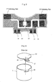
- FIG. 6 In order to reduce the man-hour of such a troublesome work, a printed board mounting method as shown in FIG. 6 is conventionally well known (refer to Japanese Utility Model Publication No. 63-127254).
- a printed board 25 to which an electric element (omitted in the drawing) is attached is structured such that it is mounted to a metal case 1 where the motor main body (omitted in the drawing) is contained, and after that, furthermore, it is covered by a case cover (omitted in the drawing).
- a projecting needle part 26 projected from an opening end edge is provided, and in the meantime, corresponding to this projecting needle part 26, to the printed board 25, an engaging part 28 which makes the projecting needle part 26 pass to an earth electrode part 27 is provided.
- the printed board 25 is mounted on the metal case 1, and after that, by performing the soldering of the projecting needle part 26 and the earth electrode part 27, the earth electrode part 27 of the printed board 25 and the metal case 1 are electrically connected through the solder.
- the small-sized motor of the present invention includes: a hollow cylindrical metal case with a bottom where a magnet is attached to an inside periphery; a synthetic resin case cover which is fitted to close an opening part of the above described case; and a rotor where a laminated core, a winding wound around the above described laminated core, and a commutator are attached on a shaft.
- a printed board where an electric circuit including an electric element is attached is mounted.
- the printed board has a soldering part which is connected to a member attached to the interior of the case cover for being connected to an electric power source supplied from the outside and a soldering part which is connected to a projection in a notch provided on the opening part side of the above described metal case for body-earthing the earth of the electric circuit.
- a pair of electrodes are brought into contact from the outside of the metal case near the above described soldering part to weld the above described soldering part by the principle of electric resistance welding, after fitting the case cover to the metal case opening part.
- a synthetic resin case cover is fitted to close an opening part of the above described case.
- a printed board where an electric circuit including an electric element is attached is mounted.
- the printed board has a soldering part which is connected to a member attached to the interior of the case cover for being connected to an electric power source supplied from the outside and a soldering part which is connected to a projection in a notch provided on the opening part side of the above described metal case for body-earthing the earth of the electric circuit.
- FIG. 1 is a vertical cross sectional view showing a total of a small-sized motor to which the present invention can be applied by an upper half cross section.
- a magnet 2 (refer to FIG. 4D) is attached to an inside periphery of a case 1 formed like a hollow cylinder with a bottom by a metal material.
- a synthetic resin case cover 11 is fitted, and the opening part is closed by the case cover 11.
- a bearing 3 for a shaft 21 is contained in a center of the case cover 11.
- the other end of the shaft 21 is supported by a bearing 3 provided at a center of the bottom part of the hollow cylindrical case 1 with a bottom.
- a laminated core 22, a winding 23 wound on the above described core 22, and a commutator 24 are usually provided to compose a rotor of a small-sized motor. Then, each of a pair of carbon brushes coming into contact with this commutator 24 is attached to the brush device fixed to the case cover 11.
- FIG. 3 is a view showing only a case cover of a small-sized motor shown in FIG. 1.
- FIG. 3A is a view of an interior seen from an inside direction of the case cover
- FIG. 3B is a cross sectional view made by cutting the case cover shown in FIG. 3A at the center.
- the brush device is made of a pair of carbon brushes 4 coming into sliding contact with the commutator, brush arms 5 where they are respectively pressed and held, and brush bases 6, 7 connected to these brush arms 5 by caulking or the like.
- the brush device structured like this is pressed and held in the concave place limited by the columned part integrally formed with that.
- the electric power source supply to this brush device is performed through a pair of brush springs 8 functioning as the receptacle terminals coming into electric contact with a pair of external terminals inserted from the outside through the external terminal inserting holes.
- one brush spring is connected to the brush base 6 electrically directly, and the other brush spring is connected to the brush base 7 in series through the choke coil 16.
- the above described attachment configuration of the brush device and electric power source supply configuration thereto can be made by a conventionally well known normal technique.
- the present invention is characterized by such a structure where to the case cover of a small-sized motor to which a brush device like this is attached, a printed board 12 to which an electric circuit element for the reduction of noise is attached is furthermore mounted, and in the meantime, the earth of this electric circuit is body-earthed to the metal case.
- FIG. 2 a typical electric circuit used for the reduction of noise is exemplified.
- Three circuits shown in (A) to (C) themselves are well known, but which circuit should be used (or whether another circuit should furthermore be used) is determined by the target value of how much the electric noise should be reduced.
- a choke coil L of the circuit element shown in the drawing can directly be attached to the case cover as mentioned above (refer to the choke coil 16 shown in FIG. 3 (A)). Chip capacitors C1 to C3 except for the choke coil L and the winding thereof are put into practice by using the printed circuit.
- FIG. 5 is a view exemplifying the printed board.
- the exemplified printed board in order to make the circuit shown in FIG. 2A, as an electric element, only one chip capacitor 15 is attached.
- the printed board for example, at the time of changing from the circuit shown in FIG. 2A to the circuit shown in FIG. 2B or FIG. 2C, or to another circuit, the changing can be performed only by changing the printed board itself where the circuit element is assembled without changing the assembled structure of the case cover at all.
- a slant hatching portion shows a winding portion on the printed board, and the soldering is performed at a black portion.
- soldering parts 17, 18, the soldering is performed with the extension parts 13 extending upward from the end parts of a pair of brush springs 8. Consequently, not only being electrically connected but also the printed board pressed and held in the concave place limited by the columned part formed integrally with the synthetic resin case cover is mechanically surely fixed in the case cover by this soldering. Consequently, the assembling of the case cover itself is finished, and after that, the step advances to the assembling step of the total of the small-sized motor.
- a metal case to which a magnet is attached, a rotor where the assembly is completed, and a case cover where the assembly is completed are prepared. Then, after letting one end of the rotor shaft pass through the bearing at the metal case bottom part, the case cover is fitted to the opening part of the metal case, and after that, not only the soldering part 14 on the printed board is mechanically connected to the projection in the notch provided to the case cover to be described later by soldering but also it is body-earthed, so that the assembling as the small-sized motor is completed.
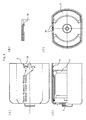
- FIG. 4 is a view showing the metal case
- FIG. 4D is a view made by seeing an interior from an opening part of the metal case, and a view made by seeing this drawing (FIG. 4D) from the upper side is FIG. 4A, and a view showing that by an upper half cross section seen from the side is FIG. 4C.
- FIG. 4B is a view showing an expanded projection 10 provided on the opening part side of the metal case.
- the projection 10 in the notch 9 provided to the metal case is provided at such a position where the soldering part 14 on the printed board comes into contact with this projection 10 when the case cover is fitted to the metal case opening part.
- solder of a specified amount is already heaped up in advance before fitting the case cover.
- the tip of the projection 10 is positioned at a place retreated from the metal case opening part end surface by an amount approximately equal to the amount by which the soldering part 14 is made higher with the heaped solder.
- two projections 10 are provided in the notches 9, and furthermore, corresponding thereto, the soldering parts 14 are provided at four places (refer to FIG.
- the projection 10 comes into contact with the soldering part 14 on the printed board, and even if part thereof bites in, the connection is not completed yet in this state.
- the solder is melted by the principle of the electric resistance welding to make the contact and the connection more stable.
- This electric resistance welding is performed by bringing a pair of electrodes for the electric resistance welding into contact with a part where heating is necessary, that is, a place near the projection 10 (refer to FIG. 4A). However, as mentioned above, the electric resistance welding is performed after fitting the case cover to the metal case.
- the heating is performed between the electrodes because of the electric resistance included in the steel metal case, and the heat thereof is transmitted to the projection 10, and consequently, the solder is melted by the principle of the electric resistance welding, and the welding is performed.
- the present invention makes it possible to easily and surely body-earth the earth of the electric circuit made of the electric element such as a chip capacitor attached on a printed board mounted to a case cover, to a metal case.
- the present invention makes it possible to reduce the number of motor assembling steps to perform the assembling with a good workability.
- the projection in the notch can prevent the solder from running over in the outside direction of the case by bending the tip side thereof in the metal case interior direction.
Landscapes
- Engineering & Computer Science (AREA)
- Power Engineering (AREA)
- Physics & Mathematics (AREA)
- Electromagnetism (AREA)
- Motor Or Generator Frames (AREA)
- Dc Machiner (AREA)
Applications Claiming Priority (2)
| Application Number | Priority Date | Filing Date | Title |
|---|---|---|---|
| JP2001308432 | 2001-10-04 | ||
| JP2001308432A JP2003116247A (ja) | 2001-10-04 | 2001-10-04 | 小型モータ及びその製造方法 |
Publications (3)
| Publication Number | Publication Date |
|---|---|
| EP1300928A2 true EP1300928A2 (de) | 2003-04-09 |
| EP1300928A3 EP1300928A3 (de) | 2006-04-26 |
| EP1300928B1 EP1300928B1 (de) | 2013-09-11 |
Family
ID=19127745
Family Applications (1)
| Application Number | Title | Priority Date | Filing Date |
|---|---|---|---|
| EP02022087.7A Expired - Lifetime EP1300928B1 (de) | 2001-10-04 | 2002-10-02 | Kleinmotors und Verfahren zur Herstellung desselben |
Country Status (4)
| Country | Link |
|---|---|
| US (2) | US6707219B2 (de) |
| EP (1) | EP1300928B1 (de) |
| JP (1) | JP2003116247A (de) |
| CN (1) | CN1276569C (de) |
Cited By (2)
| Publication number | Priority date | Publication date | Assignee | Title |
|---|---|---|---|---|
| WO2009000290A1 (en) * | 2007-06-25 | 2008-12-31 | Sintertechnik Gmbh | A device for noise suppression of a small electric motor |
| CN105337074A (zh) * | 2014-07-25 | 2016-02-17 | 博世汽车部件(长沙)有限公司 | 电驱动装置及其滤波组件 |
Families Citing this family (16)
| Publication number | Priority date | Publication date | Assignee | Title |
|---|---|---|---|---|
| EP1503484A3 (de) * | 2003-07-23 | 2006-03-15 | Sintertechnik GmbH | Vorrichtung zur Funkentstörung von Elektrokleinmotoren |
| US7109626B2 (en) * | 2004-02-06 | 2006-09-19 | Emerson Electric Co. | Compact dynamoelectric machine |
| GB0408868D0 (en) * | 2004-04-21 | 2004-05-26 | Level 5 Networks Ltd | Checking data integrity |
| JP4428640B2 (ja) * | 2004-04-27 | 2010-03-10 | アスモ株式会社 | ブラシホルダ及びブラシホルダへの半田付け方法 |
| JP4157092B2 (ja) * | 2004-11-29 | 2008-09-24 | Tdk株式会社 | モータ |
| JP4714812B2 (ja) * | 2004-11-30 | 2011-06-29 | 並木精密宝石株式会社 | 小型ブラシレスモータ構造 |
| DE102005057398A1 (de) * | 2005-11-30 | 2007-05-31 | Robert Bosch Gmbh | Bürstenträger-Bauteil mit Masse-Kontaktblech |
| US20070256391A1 (en) | 2006-04-14 | 2007-11-08 | Mifsud Vincent D | Framing table for building panel assembly |
| US20110018380A1 (en) * | 2008-03-28 | 2011-01-27 | Mabuchi Motor Co. Ltd. | Dc motor |
| CN102280962B (zh) * | 2011-06-12 | 2014-06-11 | 浙江盛越电子科技有限公司 | 一种端盖组件及包括该端盖组件的小型电机 |
| JP5802140B2 (ja) * | 2012-02-03 | 2015-10-28 | 株式会社村上開明堂 | 給電用コネクタ |
| US20160172942A1 (en) * | 2013-07-04 | 2016-06-16 | Linak A/S | Actuator system |
| CN104348323A (zh) * | 2014-10-29 | 2015-02-11 | 广东威灵电机制造有限公司 | 一种塑封直流无刷电机和电控设备 |
| US10348165B2 (en) * | 2015-10-07 | 2019-07-09 | Nidec Corporation | Noise suppression circuit |
| DE102020100988A1 (de) * | 2020-01-16 | 2021-07-22 | Ebm-Papst St. Georgen Gmbh & Co. Kg | Baugruppe mit orthogonal zur Montagerichtung der Baugruppe montierbaren Steckverbinder |
| CN116264431A (zh) | 2021-12-14 | 2023-06-16 | 美蓓亚三美株式会社 | 电机 |
Citations (2)
| Publication number | Priority date | Publication date | Assignee | Title |
|---|---|---|---|---|
| JPS63127254U (de) | 1987-02-09 | 1988-08-19 | ||
| US5196750A (en) | 1990-09-28 | 1993-03-23 | Johnson Electric S.A. | Electric motors with electromagnetic interference reduction |
Family Cites Families (6)
| Publication number | Priority date | Publication date | Assignee | Title |
|---|---|---|---|---|
| SE365666B (de) * | 1972-08-11 | 1974-03-25 | Asea Ab | |
| GB2181305B (en) * | 1985-10-04 | 1989-09-13 | Johnson Electric Ind Mfg | Electric motors |
| JP2585553B2 (ja) | 1986-11-17 | 1997-02-26 | 株式会社リコー | 静電潜像現像用トナ− |
| JPH0750863Y2 (ja) * | 1988-06-13 | 1995-11-15 | キヤノン株式会社 | 小型直流モータ |
| US6259180B1 (en) * | 1996-07-02 | 2001-07-10 | Schlenker Enterprises, Ltd. | Motor including embedded permanent magnet rotor and method for making the same |
| CN1143424C (zh) * | 1997-03-06 | 2004-03-24 | 株式会社电装 | 插入线圈条和槽型绝缘子组件的转子生产方法和装置 |
-
2001
- 2001-10-04 JP JP2001308432A patent/JP2003116247A/ja active Pending
-
2002
- 2002-08-28 US US10/233,090 patent/US6707219B2/en not_active Expired - Lifetime
- 2002-09-29 CN CNB021435596A patent/CN1276569C/zh not_active Expired - Lifetime
- 2002-10-02 EP EP02022087.7A patent/EP1300928B1/de not_active Expired - Lifetime
-
2003
- 2003-03-12 US US10/386,724 patent/US6944934B2/en not_active Expired - Lifetime
Patent Citations (2)
| Publication number | Priority date | Publication date | Assignee | Title |
|---|---|---|---|---|
| JPS63127254U (de) | 1987-02-09 | 1988-08-19 | ||
| US5196750A (en) | 1990-09-28 | 1993-03-23 | Johnson Electric S.A. | Electric motors with electromagnetic interference reduction |
Cited By (2)
| Publication number | Priority date | Publication date | Assignee | Title |
|---|---|---|---|---|
| WO2009000290A1 (en) * | 2007-06-25 | 2008-12-31 | Sintertechnik Gmbh | A device for noise suppression of a small electric motor |
| CN105337074A (zh) * | 2014-07-25 | 2016-02-17 | 博世汽车部件(长沙)有限公司 | 电驱动装置及其滤波组件 |
Also Published As
| Publication number | Publication date |
|---|---|
| EP1300928B1 (de) | 2013-09-11 |
| CN1411128A (zh) | 2003-04-16 |
| EP1300928A3 (de) | 2006-04-26 |
| CN1276569C (zh) | 2006-09-20 |
| US6944934B2 (en) | 2005-09-20 |
| JP2003116247A (ja) | 2003-04-18 |
| US20030067226A1 (en) | 2003-04-10 |
| US20030173848A1 (en) | 2003-09-18 |
| US6707219B2 (en) | 2004-03-16 |
Similar Documents
| Publication | Publication Date | Title |
|---|---|---|
| US6707219B2 (en) | Small-sized motor and manufacturing method thereof | |
| JP2608710B2 (ja) | 電動工具用整流子電動機における配線装置 | |
| US6992414B2 (en) | EMI suppression in permanent magnet DC motors having PCB outside motor in connector and overmolded | |
| US6768243B1 (en) | Small-size motor brush assembly with electrical noise suppression | |
| US5066878A (en) | Small-sized electric motor housing circuit breaker | |
| EP1732195B1 (de) | Bürstenloser Motor | |
| GB2248348A (en) | Supporting suppression elements on a brush holder | |
| JPH07194063A (ja) | 小型モータ及びモータ内蔵の電子部品の接続方法 | |
| US6057749A (en) | Structure and method for connection of an electrical component to an electromagnetic relay | |
| EP0607032A1 (de) | Miniaturmotor | |
| JPH0759288A (ja) | ブラシレスモータのステータ | |
| US20020121834A1 (en) | Rotor for small motors and manufacturing method therefor | |
| EP1009087B1 (de) | Elektrischer Kleinmotor | |
| CN114938695B (zh) | 具有一体式固定结构的用于定子绕组的电路板 | |
| JP3305241B2 (ja) | 小型モータ | |
| US6376962B1 (en) | Electric drive unit for vehicle systems | |
| JP2001008414A (ja) | モータ | |
| JPH1042504A (ja) | 回転電機のステータ | |
| JP3683222B2 (ja) | 小型モータ | |
| JP2669086B2 (ja) | 小形電動機 | |
| US6894419B2 (en) | Current passing circuit board for rotary electric machine inserted in molded resin | |
| US7362020B2 (en) | Commutator housing with an overcurrent protection device | |
| JP2000287413A (ja) | 小型モータ及びその製造方法 | |
| JPH10325842A (ja) | 回転速度センサー及びその製作方法 | |
| JPWO2001039354A1 (ja) | 小型モータ |
Legal Events
| Date | Code | Title | Description |
|---|---|---|---|
| PUAI | Public reference made under article 153(3) epc to a published international application that has entered the european phase |
Free format text: ORIGINAL CODE: 0009012 |
|
| AK | Designated contracting states |
Designated state(s): AT BE BG CH CY CZ DE DK EE ES FI FR GB GR IE IT LI LU MC NL PT SE SK TR Kind code of ref document: A2 Designated state(s): AT BE BG CH CY CZ DE DK EE ES FI FR GB GR IE IT LI LU MC NL PT SE SK TR |
|
| AX | Request for extension of the european patent |
Extension state: AL LT LV MK RO SI |
|
| PUAL | Search report despatched |
Free format text: ORIGINAL CODE: 0009013 |
|
| AK | Designated contracting states |
Kind code of ref document: A3 Designated state(s): AT BE BG CH CY CZ DE DK EE ES FI FR GB GR IE IT LI LU MC NL PT SE SK TR |
|
| AX | Request for extension of the european patent |
Extension state: AL LT LV MK RO SI |
|
| 17P | Request for examination filed |
Effective date: 20060505 |
|
| AKX | Designation fees paid |
Designated state(s): DE FR GB IT |
|
| 17Q | First examination report despatched |
Effective date: 20090507 |
|
| REG | Reference to a national code |
Ref country code: DE Ref legal event code: R079 Ref document number: 60245500 Country of ref document: DE Free format text: PREVIOUS MAIN CLASS: H02K0011000000 Ipc: H02K0005150000 |
|
| RIC1 | Information provided on ipc code assigned before grant |
Ipc: H02K 5/14 20060101ALN20130313BHEP Ipc: H02K 11/02 20060101ALI20130313BHEP Ipc: H02K 11/00 20060101ALI20130313BHEP Ipc: H02K 5/22 20060101ALN20130313BHEP Ipc: H02K 5/15 20060101AFI20130313BHEP |
|
| GRAP | Despatch of communication of intention to grant a patent |
Free format text: ORIGINAL CODE: EPIDOSNIGR1 |
|
| INTG | Intention to grant announced |
Effective date: 20130523 |
|
| GRAS | Grant fee paid |
Free format text: ORIGINAL CODE: EPIDOSNIGR3 |
|
| GRAA | (expected) grant |
Free format text: ORIGINAL CODE: 0009210 |
|
| AK | Designated contracting states |
Kind code of ref document: B1 Designated state(s): DE FR GB IT |
|
| REG | Reference to a national code |
Ref country code: GB Ref legal event code: FG4D |
|
| REG | Reference to a national code |
Ref country code: DE Ref legal event code: R096 Ref document number: 60245500 Country of ref document: DE Effective date: 20131107 |
|
| REG | Reference to a national code |
Ref country code: DE Ref legal event code: R097 Ref document number: 60245500 Country of ref document: DE |
|
| PLBE | No opposition filed within time limit |
Free format text: ORIGINAL CODE: 0009261 |
|
| STAA | Information on the status of an ep patent application or granted ep patent |
Free format text: STATUS: NO OPPOSITION FILED WITHIN TIME LIMIT |
|
| REG | Reference to a national code |
Ref country code: FR Ref legal event code: ST Effective date: 20140630 |
|
| 26N | No opposition filed |
Effective date: 20140612 |
|
| GBPC | Gb: european patent ceased through non-payment of renewal fee |
Effective date: 20131211 |
|
| PG25 | Lapsed in a contracting state [announced via postgrant information from national office to epo] |
Ref country code: FR Free format text: LAPSE BECAUSE OF NON-PAYMENT OF DUE FEES Effective date: 20131112 Ref country code: IT Free format text: LAPSE BECAUSE OF FAILURE TO SUBMIT A TRANSLATION OF THE DESCRIPTION OR TO PAY THE FEE WITHIN THE PRESCRIBED TIME-LIMIT Effective date: 20130911 |
|
| REG | Reference to a national code |
Ref country code: DE Ref legal event code: R097 Ref document number: 60245500 Country of ref document: DE Effective date: 20140612 |
|
| PG25 | Lapsed in a contracting state [announced via postgrant information from national office to epo] |
Ref country code: GB Free format text: LAPSE BECAUSE OF NON-PAYMENT OF DUE FEES Effective date: 20131211 |
|
| PGFP | Annual fee paid to national office [announced via postgrant information from national office to epo] |
Ref country code: DE Payment date: 20210831 Year of fee payment: 20 |
|
| REG | Reference to a national code |
Ref country code: DE Ref legal event code: R071 Ref document number: 60245500 Country of ref document: DE |