EP1302660B1 - Pumpaggregat mit einer Antriebskühlung mittels der zu fördernden Flüssigkeit - Google Patents
Pumpaggregat mit einer Antriebskühlung mittels der zu fördernden Flüssigkeit Download PDFInfo
- Publication number
- EP1302660B1 EP1302660B1 EP20020022584 EP02022584A EP1302660B1 EP 1302660 B1 EP1302660 B1 EP 1302660B1 EP 20020022584 EP20020022584 EP 20020022584 EP 02022584 A EP02022584 A EP 02022584A EP 1302660 B1 EP1302660 B1 EP 1302660B1
- Authority
- EP
- European Patent Office
- Prior art keywords
- chamber
- pump
- fluid
- housing
- motor
- Prior art date
- Legal status (The legal status is an assumption and is not a legal conclusion. Google has not performed a legal analysis and makes no representation as to the accuracy of the status listed.)
- Expired - Lifetime
Links
- 238000001816 cooling Methods 0.000 title description 8
- 230000007246 mechanism Effects 0.000 claims description 76
- LCGLNKUTAGEVQW-UHFFFAOYSA-N Dimethyl ether Chemical compound COC LCGLNKUTAGEVQW-UHFFFAOYSA-N 0.000 claims description 72
- 239000012530 fluid Substances 0.000 claims description 63
- 230000000740 bleeding effect Effects 0.000 claims description 18
- XEEYBQQBJWHFJM-UHFFFAOYSA-N Iron Chemical compound [Fe] XEEYBQQBJWHFJM-UHFFFAOYSA-N 0.000 claims description 6
- PXHVJJICTQNCMI-UHFFFAOYSA-N Nickel Chemical compound [Ni] PXHVJJICTQNCMI-UHFFFAOYSA-N 0.000 claims description 6
- 238000007747 plating Methods 0.000 claims description 6
- ATUOYWHBWRKTHZ-UHFFFAOYSA-N Propane Chemical compound CCC ATUOYWHBWRKTHZ-UHFFFAOYSA-N 0.000 claims description 4
- 239000000463 material Substances 0.000 claims description 4
- ATJFFYVFTNAWJD-UHFFFAOYSA-N Tin Chemical compound [Sn] ATJFFYVFTNAWJD-UHFFFAOYSA-N 0.000 claims description 3
- XAGFODPZIPBFFR-UHFFFAOYSA-N aluminium Chemical compound [Al] XAGFODPZIPBFFR-UHFFFAOYSA-N 0.000 claims description 3
- 229910052782 aluminium Inorganic materials 0.000 claims description 3
- 229910052742 iron Inorganic materials 0.000 claims description 3
- 229910052759 nickel Inorganic materials 0.000 claims description 3
- KYKAJFCTULSVSH-UHFFFAOYSA-N chloro(fluoro)methane Chemical compound F[C]Cl KYKAJFCTULSVSH-UHFFFAOYSA-N 0.000 claims description 2
- 239000001294 propane Substances 0.000 claims description 2
- 239000004411 aluminium Substances 0.000 claims 1
- 238000007599 discharging Methods 0.000 claims 1
- 239000000446 fuel Substances 0.000 description 80
- 239000002828 fuel tank Substances 0.000 description 39
- 238000002347 injection Methods 0.000 description 10
- 239000007924 injection Substances 0.000 description 10
- 230000000694 effects Effects 0.000 description 5
- 239000007788 liquid Substances 0.000 description 3
- 238000005086 pumping Methods 0.000 description 2
- 230000009471 action Effects 0.000 description 1
- 238000002485 combustion reaction Methods 0.000 description 1
- 230000008878 coupling Effects 0.000 description 1
- 238000010168 coupling process Methods 0.000 description 1
- 238000005859 coupling reaction Methods 0.000 description 1
- 230000007423 decrease Effects 0.000 description 1
- 238000010586 diagram Methods 0.000 description 1
- 238000010438 heat treatment Methods 0.000 description 1
- 230000001105 regulatory effect Effects 0.000 description 1
- 239000000126 substance Substances 0.000 description 1
Images

Classifications
-
- F—MECHANICAL ENGINEERING; LIGHTING; HEATING; WEAPONS; BLASTING
- F04—POSITIVE - DISPLACEMENT MACHINES FOR LIQUIDS; PUMPS FOR LIQUIDS OR ELASTIC FLUIDS
- F04B—POSITIVE-DISPLACEMENT MACHINES FOR LIQUIDS; PUMPS
- F04B1/00—Multi-cylinder machines or pumps characterised by number or arrangement of cylinders
- F04B1/12—Multi-cylinder machines or pumps characterised by number or arrangement of cylinders having cylinder axes coaxial with, or parallel or inclined to, main shaft axis
- F04B1/20—Multi-cylinder machines or pumps characterised by number or arrangement of cylinders having cylinder axes coaxial with, or parallel or inclined to, main shaft axis having rotary cylinder block
- F04B1/2014—Details or component parts
-
- F—MECHANICAL ENGINEERING; LIGHTING; HEATING; WEAPONS; BLASTING
- F04—POSITIVE - DISPLACEMENT MACHINES FOR LIQUIDS; PUMPS FOR LIQUIDS OR ELASTIC FLUIDS
- F04B—POSITIVE-DISPLACEMENT MACHINES FOR LIQUIDS; PUMPS
- F04B1/00—Multi-cylinder machines or pumps characterised by number or arrangement of cylinders
- F04B1/12—Multi-cylinder machines or pumps characterised by number or arrangement of cylinders having cylinder axes coaxial with, or parallel or inclined to, main shaft axis
- F04B1/128—Driving means
-
- F—MECHANICAL ENGINEERING; LIGHTING; HEATING; WEAPONS; BLASTING
- F04—POSITIVE - DISPLACEMENT MACHINES FOR LIQUIDS; PUMPS FOR LIQUIDS OR ELASTIC FLUIDS
- F04B—POSITIVE-DISPLACEMENT MACHINES FOR LIQUIDS; PUMPS
- F04B53/00—Component parts, details or accessories not provided for in, or of interest apart from, groups F04B1/00 - F04B23/00 or F04B39/00 - F04B47/00
- F04B53/08—Cooling; Heating; Preventing freezing
-
- Y—GENERAL TAGGING OF NEW TECHNOLOGICAL DEVELOPMENTS; GENERAL TAGGING OF CROSS-SECTIONAL TECHNOLOGIES SPANNING OVER SEVERAL SECTIONS OF THE IPC; TECHNICAL SUBJECTS COVERED BY FORMER USPC CROSS-REFERENCE ART COLLECTIONS [XRACs] AND DIGESTS
- Y10—TECHNICAL SUBJECTS COVERED BY FORMER USPC
- Y10T—TECHNICAL SUBJECTS COVERED BY FORMER US CLASSIFICATION
- Y10T137/00—Fluid handling
- Y10T137/8593—Systems
- Y10T137/85978—With pump
- Y10T137/86035—Combined with fluid receiver
Definitions
- the present invention relates to a pump for exerting pressure on fluid and particularly relates to a circulation of the fluid through the pump.
- Unexamined Japanese Patent Publication No. 9-88807 discloses a pump for exerting pressure on fluid.
- the pump has an integral structure that includes a hydraulic pump (a pump mechanism) and an electric motor (a motor mechanism) in the same unit housing.
- the pump also includes an oi! passage for draining oil from the hydraulic pump into the electric motor side and then to the outside of the housing.
- the drain oil cools the electric motor.
- an introducing port for introducing oil from the outside of the housing into the inside is not provided, and only the drain oil drained from the pump cools the motor. Since cooling is performed only by the drain oil, cooling efficiency is relatively low.
- Unexamined Japanese Utility Model Publication No. 4-57693 also discloses a fluid pump.
- the fluid pump includes a pump mechanism and a motor mechanism.
- the fluid pump also includes two communication passages bored through a casing of the fluid pump, and the communication passages are located adjacent the motor mechanism. The fluid enters into the casing through one passage and exits through the other to cool the motor mechanism.
- EP-A-1 024 287 discloses a pump wherein the fluid to be compressed is sucked from a suction port 4 of a motor housing through a ring channel 6 of the motor housing, an outlet port 5 into a flange chamber 16 and from the flange chamber 16 to an inlet port of the pump, i.e. the fluid to be compressed is sucked through the motor housing before it reaches the pumping chamber of the pump 40.
- a pump exerts pressure on fluid that has higher saturation pressure than atmospheric pressure at room temperature in a fluid reserving chamber in a fluid tank.
- the pump is located near the fluid tank.
- the pump has a housing and a heat generating mechanism.
- the housing defines a pump chamber, a motor chamber and a communication passage between the pump chamber and the motor chamber and includes at least one introducing port for introducing the fluid from the fluid reserving chamber into the housing and a bleeding port located above the introducing port for returning the fluid from the housing to the fluid reserving chamber.
- the heat generating mechanism is located in the housing. The fluid circulates into the housing through the introducing port and out of the housing through the bleeding port for substantially reducing the temperature in the housing.
- a pump exerts pressure on fluid that has higher saturation pressure than atmospheric pressure at room temperature in a fluid reserving chamber in a fluid tank.
- the pump is located near the fluid tank.
- the pump has a housing, a pump mechanism and a motor mechanism.
- the housing defines a pump chamber, a motor chamber and a communication passage between the pump chamber and the motor chamber and includes an introducing port for introducing the fluid into the pump chamber and a bleeding port located above the introducing port for returning the fluid from the motor chamber to the fluid reserving chamber.
- the pump mechanism is located in the pump chamber for exerting pressure on the fluid.
- the pump mechanism generates heat.
- the motor mechanism is located in the motor chamber for driving the pump mechanism.
- the motor mechanism generates heat.
- the fluid carries the heat.
- FIG. 2 is a schematic view of a fluid fuel supply system for supplying a fuel injection device F with dimethylether fuel (DME fuel) or fluid.
- the fuel injection device F is connected to a diesel type internal combustion engine E which is a drive source of a vehicle.
- This fluid fuel supply system includes a fuel tank 11 and a fuel pump 12.
- the fuel tank 11 functions as a fluid tank to reserve the DME.
- the fuel pump 12 is placed in the fuel tank 11 and functions as a pump for exerting pressure on the fluid to supply the fuel injection device F with the DME in the liquid form from the fuel tank 11.
- the above-mentioned DME has higher saturation pressure than atmospheric pressure at room temperature.
- the fuel tank 11 isolates the inside space of the tank 11 and maintains its inside pressure independent from the outside pressure.
- the fuel tank 11 and the fuel pump 12 constitute a fuel tank unit or a fluid tank unit.
- the fuel pump 12 is substantially accommodated in the fuel tank 11.
- the fuel pump 12 is fixed to the bottom end of the fuel tank 11.
- the fuel pump 12 communicates with the fuel injection device F through a supply conduit 13 for supplying the fuel injection device F with the DME discharged from the fuel pump 12.
- the fuel injection device F communicates with the fuel tank 11 through a return conduit 17 to the fuel tank 11.
- the redundant DME which was supplied from the fuel pump 12 to the fuel injection device F, but was not fully utilized by the fuel injection device F, returns through the return conduit 17.
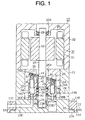
- a housing of the fuel pump 12 includes a center housing 21, a motor housing 22 and a base housing 23.
- the motor housing 22 is secured by bolts to the upper end of the center housing 21.
- the base housing 23 is secured by bolts to the lower end of the center housing 21. The bolts are not shown in the drawing.
- a through hole 11A is formed through the fuel tank 11.
- An annular mounting base 11B is welded to the through hole 11A of the fuel tank 11.
- the fuel pump 12 is secured to the fuel tank 11.
- the base housing 23 of the fuel pump 12 is secured to the mounting base 11B of the fuel tank 11 by bolts, which are not shown in the drawing.
- a gasket 15 is interposed between an upper surface of a flange 23A formed around an outer periphery of the base housing 23 and the mounting base 11B so as to seal a gap therebetween.
- the fuel pump 12 is placed in the fuel tank 11 in a manner that the lower end of the base housing 23 being exposed outside the fuel tank 11.
- a space outside the housing of the fuel pump 12 and in the fuel tank 11 is a fuel reserving chamber or a fluid reserving chamber of the fuel tank 11.
- a pump chamber 24 is defined in the center housing 21.
- a motor chamber 25 is defined in the motor housing 22.
- the motor chamber 25 is disposed vertically above the pump chamber 24.
- the pump chamber 24 and the motor chamber 25 are partitioned by a center block 26 in the center housing 21 and are interconnected by a communication passage 26A.
- the communication passage 26A located adjacent the upper side of the pump chamber 24 functions as a bleeding port for bleeding the DME in the pump chamber 24 to the motor chamber 25.
- the pump chamber 24 communicates with the outside of the housing or the fuel reserving chamber through a communication passage 21A which is formed in the center housing 21.
- the communication passage 21A is located adjacent to the lower side of the pump chamber 24.
- the communication passage 21A also interconnects an introducing port 24A for introducing the DME in the fuel reserving chamber into the pump chamber 24 and an opening 21B located adjacent to the introducing port 24A.
- a drive shaft 27 is rotatably supported in the housing so as to extend through the pump chamber 24, the communication passage 26A and the motor chamber 25. Even if the drive shaft 27 is inserted through the communication passage 26A, a clearance between the drive shaft 27 and the communication passage 26A is maintained to interconnect the pump chamber 24 and the motor chamber 25.
- the upper end of the drive shaft 27 is supported in the motor housing 22 by a ball bearing 28 fitted in a mounting hole or a bleeding port 22A which is located adjacent to the upper side of the motor chamber 25.
- the motor chamber 25 communicates with the outside of the housing or the fuel reserving chamber through the mounting hole 22A.
- the lower end of the drive shaft 27 is supported by a bearing 29 fitted in a mounting recess 23B which is formed in the base housing 23.
- a motor mechanism 30 is arranged in the motor chamber 25.
- the motor mechanism 30 in the motor chamber 25 includes a stator 31 that is secured to an inner circumferential surface of the motor housing 22.
- the motor mechanism 30 also includes a rotor 32 that is secured to the drive shaft 27 in the motor chamber 25 and is located to face the stator 31.
- the motor mechanism 30 is configured to drive the drive shaft 27 in accordance with the rotation of the rotor 32 by an electric current supplied from an outside to the stator 31.
- An axial piston pump mechanism 33 is arranged in the pump chamber 24.
- the piston pump mechanism 33 includes a cylinder block 34 that engages the drive shaft 27 by means of spline engagement to rotate integrally with the drive shaft 27 and to move in the axial direction relative to the drive shaft 27 in the pump chamber 24.
- the cylinder block 34 includes a plurality of cylinder bores 34A around the drive shaft 27. Two cylinder bores are illustrated in FIG.1.
- the pump mechanism 33 and the motor mechanism 30 correspond to a heat generating mechanism.
- a piston 35 is accommodated in each cylinder bore 34A so as to reciprocate therein.
- a cam surface 26B is formed on the center block 26 and is at a predetermined angle with respect to an axial direction of the drive shaft 27.
- a shoe 36 is slidable to face the cam surface 26B and is coupled to each piston 35 through a ball coupling 37.
- the bottom end of the pump chamber 24 is defined by a part of the upper end surface of the base housing 23.
- a valve port forming plate 38 is fixed to the upper end surface of the base housing 23.
- the upper end surface of the valve port forming plate 38 and the lower end surface of the cylinder block 34 are slidable to each other with the surfaces contacting to each other.
- a suction port 38A and a discharge port 38B each are formed in the valve port forming plate 38.
- the suction port 38A and the discharge port 38B respectively have an opening at the upper side and the lower side of the valve port forming plate 38.
- An inlet 11C is formed in the mounting base 11B, and a suction passage 23C is formed in the base housing 23.
- the suction passage 23C communicates the inlet 11C with the suction port 38A.
- the inlet 11C is located near the lowest position of the fuel reserving chamber.
- the supply conduit 13 as shown in FIG. 2 is connected to the discharge port 38B at an outlet 23D formed in the base housing 23.
- a chamber 34B is defined near the center of the cylinder block 34.
- a coil spring 39 is in the chamber 34B and surrounds the drive shaft 27.
- the urging force of the coil spring 39 is applied to the cylinder block 34 through a spring seat 40 fixed to the cylinder block 34 and is also applied to a shoe retainer 44 through a spring seat 41, a pin 42 and a pivot 43.
- the shoe retainer 44 engages the shoe 36, and the shoe 36 is pressed against the cam surface 26B by the urging force applied to the shoe retainer 44.
- the cylinder block 34 is pressed against the valve port forming plate 38 by the urging force applied to the spring seat 40.
- each piston 35 reciprocates within a predetermined stroke distance as it is regulated by an inclination angle of the cam surface 26B.
- Each cylinder bore 34A alternately communicates with the suction port 38A and the discharge port 38B of the valve port forming plate 38. Accordingly, the DME in the fuel reserving chamber is introduced into the cylinder bores 34A through the inlet 11C, the suction passage 23C and the suction port 38A, and the DME in the cylinder bores is subsequently discharged through the discharge port 38B by pumping action. The discharged DME is sent to the fuel injection device F through the outlet 23D and the supply conduit 13.
- the motor mechanism 30 drives the piston pump mechanism 33
- heat is generated by friction at each sliding portion of the piston pump mechanism 33, and by the rotation of the motor mechanism 30.
- the generated heat heats the DME in the pump chamber 24 and the motor chamber 25. Due to the heating, the DME flows from the lower side toward the upper side in the chambers 24 and 25 by an upward convection current of the heated DME and the vaporized DME bubbles.
- the DME in the fuel reserving chamber is introduced into the pump chamber 24 through the opening 21B, the communication passage 21A and the introducing port 24A.
- the DME in the pump chamber 24 is subsequently further introduced into the motor chamber 25 through the communication passage 26A.
- the DME in the motor chamber 25 passes through the clearance between the stator 31 and the rotor 32 of the motor mechanism 30 and finally returns to the fuel reserving chamber through the clearance in the ball bearing 28, and the mounting hole 22A. Due to the above-described flow of DME, the piston pump mechanism 33 and the motor mechanism 30 are effectively cooled.
- the DME in the motor chamber 25 is bled to outside the housing through the mounting hole 22A.
- the DME may be bled to outside the housing through another hole or a bleeding passage defined near the upper side of the motor chamber 25.
- the introducing port 24A does not require to be located near the lower side of the pump chamber 24.
- the introducing port 24A may be located near the center block 26 or the upper side of the pump chamber 24.
- a check valve is placed in either one of the communication passage 21A, the opening 21B and the introducing port 24A to permit the DME to flow from the fuel reserving chamber to the pump chamber 24 and to block the DME to flow from the pump chamber 24 to the fuel reserving chamber.
- the DME in the pump chamber 24 does not flow to the fuel reserving chamber through the introducing port 24A, the communication passage 21A and the opening 21B.
- the pump chamber 24 and the motor chamber 25 are readily filled with the DME that circulates for cooling, and the piston pump mechanism 33 and the motor mechanism 30 are effectively is maintained at a desirable temperature.
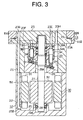
- the introducing port 25A is remotely located from the boundary between the pump chamber 24 and the motor chamber 25.
- the introducing port 25A is located at the opposite side of the center block 26 relative to the motor mechanism 30.
- the introducing port 25A and the opening 22B are omitted, and the DME in the fuel reserving chamber is introduced into the motor chamber 25 through the mounting hole 22A.
- the mounting hole 22A corresponds to an introducing port adjacent to the motor chamber 25.
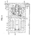
- the fuel pump 12 is arranged substantially outside the fuel tank 11, and the pump chamber 24 is located above the motor chamber 25. In an alternative embodiment, the fuel pump 12 is arranged substantially outside the fuel tank 11. However, the chambers 24 and 25 are disposed in a substantially horizontal manner.
- a filter is placed at the opening that communicates with the introducing port and that is defined on the outer circumferential surface of the housing. The filter prevents foreign substances from flowing into the housing.
- the cylinder block 34 and the piston 35 are respectively made of aluminum and iron.
- Aluminum has a higher thermal expansion coefficient than iron.
- the clearance between the cylinder block 34 and the piston 35 increases due to the above difference in thermal expansion coefficient.
- the lack of the difference in thermal expansion coefficient causes insufficient clearance at a high temperature and leads to undesirable seizure between the two components.
- the clearance is preferably 10 ⁇ m or below.
- sliding regions are optionally coated with frictional resistance reducing material such as fluororesin.
- the sliding regions include areas between the cylinder block 34 and the valve port forming plate 38, and between the piston 35, 37 and the shoe 36, and between the shoe 36 and the cam surface 26B of the center block 26. Thereby, seizure is effectively prevented in the sliding regions.
- pressure of a liquid coat of the DME prevents sliding resistance at the sliding regions from increasing, frictional resistance reducing material itself hardly abrades.
- a sliding region between the cylinder block 34 and the piston 35 is coated with frictional resistance reducing material such as nickel plating or tin plating.
- each sliding region of the bearings 28 and 29 is coated with frictional resistance reducing means such as nickel plating and tin plating.
- a piston pump instead of the axial piston pump mechanism 33, a piston pump employs other mechanisms such as a radial piston pump mechanism, a gear pump mechanism, a centrifugal pump mechanism, a screw pump mechanism and a roots pump mechanism.
- freon chlorofluorocarbon
- propane is employed as fluid that has higher saturation pressure than atmospheric pressure at room temperature.
Landscapes
- Engineering & Computer Science (AREA)
- Mechanical Engineering (AREA)
- General Engineering & Computer Science (AREA)
- Details Of Reciprocating Pumps (AREA)
- Reciprocating Pumps (AREA)
Claims (18)
- Pumpe, die einen Druck auf ein Fluid, das bei Raumtemperatur einen höheren Sättigungsdruck hat als ein Atmosphärendruck in einer Fluidvorratskammer eines Fluidbehälters (11), durch Einleiten des Fluids durch eine Ansauganschluss (38a) und Auslassen des komprimierten Fluids durch einen Auslassanschluss (38b) ausübt, wobei die Pumpe folgendes aufweist:ein Gehäuse, das eine Pumpenkammer (24) und eine Motorkammer (25) definiert,gekennzeichnet durch
wenigstens einen Einleitungsanschluss (24A, 25A, 25B) für ein Einleiten des Fluids von der Vorratskammer in das Gehäuse; und
einem Abzweiganschluss (22C, 21C, 23H), der oberhalb des Einleitungsanschlusses (24A, 25A, 25B) für ein Rückführen des Fluids von dem Gehäuse zu der Fluidvorratskammer gelegen ist, wobei die Pumpenkammer (24) und die Motorkammer (25) durch eine Verbindungspassage (26A) miteinander verbunden sind, so dass Wärme, die durch einen Wärmeerzeugungsmechanismus erzeugt wird, der in dem Gehäuse gelegen ist, das Fluid durch den Einleitungsanschluss (24A, 25A, 25B) in das Gehäuse hinein und durch den Abzweiganschluss (22A, 22C, 21C, 23H) aus dem Gehäuse heraus für ein wesentliches Verringern der Temperatur in dem Gehäuse zirkulieren lässt. - Pumpe gemäß Anspruch 1, wobei der Einleitungsanschluss (24A, 25A) an dem Gehäuse nahe einem Bodenabschnitt der Pumpenkammer (24) gelegen ist.
- Pumpe gemäß Anspruch 1, wobei der Einleitungsanschluss (25B) an dem Gehäuse nahe einem Bodenabschnitt der Motorkammer (25) gelegen ist.
- Pumpe gemäß Anspruch 1, wobei der Einleitungsanschluss (24A, 25A) die Fluidvorratskammer und die Pumpenkammer (24) mit einem minimalen Abstand für das Verringern des Strömungswiderstands des Fluids verbindet.
- Pumpe gemäß Anspruch 1, wobei der Einleitungsanschluss (25a, 25b) die Fluidvorratskammer und die Motorkammer (25) mit einem minimalen Abstand für ein Verringern des Strömungswiderstands des Fluids verbindet.
- Pumpe gemäß Anspruch 1, wobei das Gehäuse im Wesentlichen in dem Fluidbehälter (11) beherbergt ist.
- Pumpe gemäß Anspruch 1, wobei die Pumpenkammer (24) und die Motorkammer (25) in einer im Wesentlichen vertikalen Weise angeordnet sind, und der Einleitungsanschluss (24A) nur nahe einer Bodenseite des Gehäuses vorgesehen ist.
- Pumpe gemäß Anspruch 1, wobei die Pumpenkammer (24) und die Motorkammer (25) in einer im Wesentlichen horizontalen Weise angeordnet sind.
- Pumpe gemäß Anspruch 8, wobei der Einleitungsanschluss (25A) nahe einer Grenze zwischen der Pumpenkammer (24) und der Motorkammer (25) gelegen ist, wobei der Abzweiganschluss (22C, 21C) nahe jeder der Kammern gelegen ist, wobei das Fluid in jeder der Kammern zu der Fluidvorratskammer durch die Abzweiganschlüsse zurückgeführt wird.
- Pumpe gemäß Anspruch 1, wobei der Wärmeerzeugungsmechanismus ein Pumpmechanismus ist, der einen Pumpmechanismus (33) der Axialkolbenart umfasst.
- Pumpe gemäß Anspruch 1, wobei der Wärmeerzeugungsmechanismus ein Motormechanismus (30) ist.
- Pumpe gemäß Anspruch 1, wobei der Wärmeerzeugungsmechanismus ein Pumpenmechanismus (33) ist, der eine Zylinderblock (34), der aus Aluminium gemacht ist, und einen Kolben (35) hat, der aus Eisen gemacht ist.
- Pumpe gemäß Anspruch 12, wobei ein Abstand zwischen dem Zylinderblock (34) und dem Kolben (35) bei Raumtemperatur ungefähr 10 µm oder weniger ist.
- Pumpe gemäß Anspruch 12, wobei eine Gleitregion zwischen dem Zylinderblock (34) und dem Kolben (35) mit einem Reibungswiderstandverringernden Material bedeckt ist, das von der Gruppe gewählt ist, die aus einem Nickelüberzug und aus einem Zinnüberzug besteht.
- Pumpe gemäß Anspruch 1, wobei das Fluid von der Gruppe gewählt ist, die aus Dimethylether, Chlorfluorkohlenstoff und Propan besteht.
- Pumpe gemäß Anspruch 1, wobei die Pumpenkammer (24) oberhalb der Motorkammer (25) gelegen ist.
- Pumpe gemäß Anspruch 1, wobei die Motorkammer (25) oberhalb der Pumpenkammer (24) gelegen ist.
- Fluidbehältereinheit mit:einem Fluidbehälter (11), der eine Fluidvorratskammer für ein Bevorraten von Fluid hat, das bei Raumtemperatur einen höheren Sättigungsdruck hat als ein Atmosphärendruck; undeiner Pumpe gemäß einem der vorhergehenden Ansprüche, die mit dem Fluidbehälter verbunden ist.
Applications Claiming Priority (2)
| Application Number | Priority Date | Filing Date | Title |
|---|---|---|---|
| JP2001311522A JP4066633B2 (ja) | 2001-10-09 | 2001-10-09 | 流体加圧ポンプおよび流体タンクユニット |
| JP2001311522 | 2001-10-09 |
Publications (3)
| Publication Number | Publication Date |
|---|---|
| EP1302660A2 EP1302660A2 (de) | 2003-04-16 |
| EP1302660A3 EP1302660A3 (de) | 2005-03-30 |
| EP1302660B1 true EP1302660B1 (de) | 2006-12-20 |
Family
ID=19130343
Family Applications (1)
| Application Number | Title | Priority Date | Filing Date |
|---|---|---|---|
| EP20020022584 Expired - Lifetime EP1302660B1 (de) | 2001-10-09 | 2002-10-08 | Pumpaggregat mit einer Antriebskühlung mittels der zu fördernden Flüssigkeit |
Country Status (4)
| Country | Link |
|---|---|
| US (1) | US6913038B2 (de) |
| EP (1) | EP1302660B1 (de) |
| JP (1) | JP4066633B2 (de) |
| DE (1) | DE60216871T2 (de) |
Families Citing this family (15)
| Publication number | Priority date | Publication date | Assignee | Title |
|---|---|---|---|---|
| GB0226101D0 (en) * | 2002-11-08 | 2002-12-18 | Rhodia Cons Spec Ltd | White rust corrosion inhibitors |
| AT501235B1 (de) * | 2004-11-23 | 2006-12-15 | Hoerbiger Automatisierungstech | Hydraulisches kombinationsaggregat |
| DE102006042810A1 (de) * | 2006-09-08 | 2008-03-27 | Voith Turbo Gmbh & Co. Kg | Hydrostatische Energieerzeugungseinheit |
| US7428862B2 (en) * | 2006-12-08 | 2008-09-30 | Honeywell International Inc. | Cladded axial motor/pump piston and method of producing same |
| JP4833237B2 (ja) * | 2008-03-03 | 2011-12-07 | 川崎重工業株式会社 | 電動機一体型油圧モータ |
| JP4740983B2 (ja) * | 2008-06-18 | 2011-08-03 | 三菱電機株式会社 | 燃料供給装置 |
| JP2010233701A (ja) * | 2009-03-30 | 2010-10-21 | Maguna:Kk | 磁石製留め金具及び留め具製造方法 |
| KR101072363B1 (ko) | 2009-05-13 | 2011-10-12 | (주)모토닉 | 인-탱크 펌프 |
| KR20110021573A (ko) * | 2009-08-26 | 2011-03-04 | 현대자동차주식회사 | Lpi엔진의 연료 공급 시스템 |
| JP5682219B2 (ja) * | 2010-10-14 | 2015-03-11 | いすゞ自動車株式会社 | Dme自動車の燃料供給システム |
| ITRE20150032A1 (it) * | 2015-04-16 | 2016-10-16 | Annovi Reverberi Spa | Gruppo motopompa per idropulitrici |
| JP6550274B2 (ja) * | 2015-06-11 | 2019-07-24 | 株式会社ニッキ | 燃料供給装置 |
| US12196160B2 (en) | 2019-04-12 | 2025-01-14 | Auto Gas Services, LLC | Liquid injected propane fuel system |
| US11760228B2 (en) * | 2021-05-11 | 2023-09-19 | Hyundai Motor Company | Electric power and thermal management system |
| KR20220153400A (ko) | 2021-05-11 | 2022-11-18 | 현대자동차주식회사 | 프로펠러용 구동기를 이용한 오일 분산 시스템 |
Family Cites Families (18)
| Publication number | Priority date | Publication date | Assignee | Title |
|---|---|---|---|---|
| US1800833A (en) * | 1925-08-20 | 1931-04-14 | Universal Oil Prod Co | Method and means for cooling packing of hot-oil pumps |
| US2510632A (en) * | 1945-11-27 | 1950-06-06 | Gen Electric | Machine cooling system |
| US3175758A (en) * | 1962-04-30 | 1965-03-30 | Lennox Ind Inc | Compressor construction with inertial suction valve |
| US3610784A (en) * | 1970-03-19 | 1971-10-05 | Tecumseh Products Co | Electric motor and compressor construction |
| US4190402A (en) * | 1975-05-06 | 1980-02-26 | International Telephone And Telegraph Corporation | Integrated high capacity compressor |
| JPH0427157A (ja) | 1990-05-22 | 1992-01-30 | Seiko Epson Corp | 半導体装置 |
| JP2716046B2 (ja) | 1990-06-22 | 1998-02-18 | オリンパス光学工業株式会社 | ロボットハンド |
| JPH0988807A (ja) | 1995-09-28 | 1997-03-31 | Yuken Kogyo Co Ltd | モータ一体型油圧ポンプ装置 |
| DE19628781A1 (de) * | 1996-07-17 | 1998-01-22 | Voith Turbo Kg | Pumpaggregat mit einer Antriebskühlung mittels der zu fördernden Flüssigkeit |
| JPH1068396A (ja) | 1996-08-27 | 1998-03-10 | Ishikawajima Harima Heavy Ind Co Ltd | ターボポンプ |
| DE19711591A1 (de) * | 1997-03-20 | 1998-09-24 | Fluidtech Gmbh | Fluidkühlvorrichtung |
| JPH10331769A (ja) * | 1997-05-30 | 1998-12-15 | Zexel Corp | 冷媒圧縮機 |
| DE29809935U1 (de) * | 1998-06-03 | 1998-10-08 | Heilmeier & Weinlein Fabrik für Oel-Hydraulik GmbH & Co KG, 81673 München | Hydraulisches Motor-Pumpenaggregat |
| US6447270B1 (en) * | 1998-09-17 | 2002-09-10 | Walbro Corporation | Brushless coolant pump and cooling system |
| JP2000320907A (ja) | 1999-05-06 | 2000-11-24 | Hitachi Ltd | 密閉形電動圧縮機 |
| JP2001193639A (ja) * | 2000-01-11 | 2001-07-17 | Toyota Autom Loom Works Ltd | 電動斜板圧縮機 |
| JP2003028055A (ja) | 2001-07-18 | 2003-01-29 | Toyota Industries Corp | 流体圧送装置及び流体貯留用タンク |
| JP2003113780A (ja) | 2001-07-30 | 2003-04-18 | Toyota Industries Corp | 軸封装置 |
-
2001
- 2001-10-09 JP JP2001311522A patent/JP4066633B2/ja not_active Expired - Fee Related
-
2002
- 2002-10-07 US US10/265,987 patent/US6913038B2/en not_active Expired - Fee Related
- 2002-10-08 EP EP20020022584 patent/EP1302660B1/de not_active Expired - Lifetime
- 2002-10-08 DE DE2002616871 patent/DE60216871T2/de not_active Expired - Lifetime
Also Published As
| Publication number | Publication date |
|---|---|
| DE60216871T2 (de) | 2007-08-02 |
| JP4066633B2 (ja) | 2008-03-26 |
| EP1302660A3 (de) | 2005-03-30 |
| JP2003120451A (ja) | 2003-04-23 |
| US20030068239A1 (en) | 2003-04-10 |
| EP1302660A2 (de) | 2003-04-16 |
| DE60216871D1 (de) | 2007-02-01 |
| US6913038B2 (en) | 2005-07-05 |
Similar Documents
| Publication | Publication Date | Title |
|---|---|---|
| EP1302660B1 (de) | Pumpaggregat mit einer Antriebskühlung mittels der zu fördernden Flüssigkeit | |
| US5971717A (en) | Axial piston machine having a cooling circuit for the cylinders and pistons | |
| US8689581B2 (en) | Rotary-type fluid machine and refrigeration cycle apparatus | |
| US6296457B1 (en) | Discharge pulsation damping apparatus for compressor | |
| KR102913725B1 (ko) | 저압 챔버 회전식 압축기 및 에어컨 | |
| CN101680301B (zh) | 膨胀机一体型压缩机及具备其的制冷循环装置 | |
| JP2004138059A (ja) | 水平式二段階回転圧縮機 | |
| US6862975B2 (en) | Apparatus for lubricating piston type compressor | |
| CN116134224B (zh) | 压缩机和压缩机系统 | |
| JP2015504997A (ja) | 軸方向ピストンの高圧圧縮機/ポンプ | |
| US20020176785A1 (en) | Compressor provided with sliding bearing | |
| JP2002188566A (ja) | 圧縮機における冷却構造 | |
| JPH05231309A (ja) | ピストン型圧縮機における潤滑構造 | |
| US6318502B1 (en) | Compressor for producing oil-free compressed air | |
| US20030146053A1 (en) | Lubricating structure in piston type compressor | |
| JP5413850B2 (ja) | 冷媒圧縮機 | |
| JPWO2005005803A1 (ja) | エンジン | |
| EP1983191B1 (de) | Kupplungsloser verdichter mit variabler verdrängung | |
| JPH0214695Y2 (de) | ||
| JP2715553B2 (ja) | 斜板式圧縮機 | |
| JP2003083193A (ja) | 流体燃料加圧ポンプ | |
| CN119467268B (zh) | 一种轴向柱塞泵及液压系统 | |
| JPS63100285A (ja) | 圧縮機 | |
| CN1304755C (zh) | 用于向流体加压的泵以及具有该泵的流体箱装置 | |
| KR101059063B1 (ko) | 압축기의 오일분리구조 |
Legal Events
| Date | Code | Title | Description |
|---|---|---|---|
| PUAI | Public reference made under article 153(3) epc to a published international application that has entered the european phase |
Free format text: ORIGINAL CODE: 0009012 |
|
| 17P | Request for examination filed |
Effective date: 20021008 |
|
| AK | Designated contracting states |
Designated state(s): AT BE BG CH CY CZ DE DK EE ES FI FR GB GR IE IT LI LU MC NL PT SE SK TR |
|
| AX | Request for extension of the european patent |
Extension state: AL LT LV MK RO SI |
|
| PUAL | Search report despatched |
Free format text: ORIGINAL CODE: 0009013 |
|
| AK | Designated contracting states |
Kind code of ref document: A3 Designated state(s): AT BE BG CH CY CZ DE DK EE ES FI FR GB GR IE IT LI LU MC NL PT SE SK TR |
|
| AX | Request for extension of the european patent |
Extension state: AL LT LV MK RO SI |
|
| AKX | Designation fees paid |
Designated state(s): DE FR SE |
|
| GRAP | Despatch of communication of intention to grant a patent |
Free format text: ORIGINAL CODE: EPIDOSNIGR1 |
|
| GRAS | Grant fee paid |
Free format text: ORIGINAL CODE: EPIDOSNIGR3 |
|
| GRAA | (expected) grant |
Free format text: ORIGINAL CODE: 0009210 |
|
| AK | Designated contracting states |
Kind code of ref document: B1 Designated state(s): DE FR SE |
|
| REF | Corresponds to: |
Ref document number: 60216871 Country of ref document: DE Date of ref document: 20070201 Kind code of ref document: P |
|
| REG | Reference to a national code |
Ref country code: SE Ref legal event code: TRGR |
|
| ET | Fr: translation filed | ||
| PLBE | No opposition filed within time limit |
Free format text: ORIGINAL CODE: 0009261 |
|
| STAA | Information on the status of an ep patent application or granted ep patent |
Free format text: STATUS: NO OPPOSITION FILED WITHIN TIME LIMIT |
|
| 26N | No opposition filed |
Effective date: 20070921 |
|
| REG | Reference to a national code |
Ref country code: FR Ref legal event code: ST Effective date: 20080630 |
|
| PG25 | Lapsed in a contracting state [announced via postgrant information from national office to epo] |
Ref country code: FR Free format text: LAPSE BECAUSE OF NON-PAYMENT OF DUE FEES Effective date: 20071031 |
|
| PGFP | Annual fee paid to national office [announced via postgrant information from national office to epo] |
Ref country code: DE Payment date: 20101006 Year of fee payment: 9 |
|
| PGFP | Annual fee paid to national office [announced via postgrant information from national office to epo] |
Ref country code: SE Payment date: 20101012 Year of fee payment: 9 |
|
| REG | Reference to a national code |
Ref country code: SE Ref legal event code: EUG |
|
| PG25 | Lapsed in a contracting state [announced via postgrant information from national office to epo] |
Ref country code: DE Free format text: LAPSE BECAUSE OF NON-PAYMENT OF DUE FEES Effective date: 20120501 |
|
| REG | Reference to a national code |
Ref country code: DE Ref legal event code: R119 Ref document number: 60216871 Country of ref document: DE Effective date: 20120501 |
|
| PG25 | Lapsed in a contracting state [announced via postgrant information from national office to epo] |
Ref country code: SE Free format text: LAPSE BECAUSE OF NON-PAYMENT OF DUE FEES Effective date: 20111009 |