EP1306107A2 - Rechteckige Rahmenanordnung mit ein bis zwei scheibenförmigen Strahlungsfiltern und Bräunungsmodul - Google Patents
Rechteckige Rahmenanordnung mit ein bis zwei scheibenförmigen Strahlungsfiltern und Bräunungsmodul Download PDFInfo
- Publication number
- EP1306107A2 EP1306107A2 EP02022556A EP02022556A EP1306107A2 EP 1306107 A2 EP1306107 A2 EP 1306107A2 EP 02022556 A EP02022556 A EP 02022556A EP 02022556 A EP02022556 A EP 02022556A EP 1306107 A2 EP1306107 A2 EP 1306107A2
- Authority
- EP
- European Patent Office
- Prior art keywords
- frame arrangement
- rectangular frame
- side flank
- arrangement according
- floor
- Prior art date
- Legal status (The legal status is an assumption and is not a legal conclusion. Google has not performed a legal analysis and makes no representation as to the accuracy of the status listed.)
- Granted
Links
Images



Classifications
-
- A—HUMAN NECESSITIES
- A61—MEDICAL OR VETERINARY SCIENCE; HYGIENE
- A61N—ELECTROTHERAPY; MAGNETOTHERAPY; RADIATION THERAPY; ULTRASOUND THERAPY
- A61N5/00—Radiation therapy
- A61N5/06—Radiation therapy using light
- A61N5/0613—Apparatus adapted for a specific treatment
- A61N5/0614—Tanning
-
- A—HUMAN NECESSITIES
- A61—MEDICAL OR VETERINARY SCIENCE; HYGIENE
- A61N—ELECTROTHERAPY; MAGNETOTHERAPY; RADIATION THERAPY; ULTRASOUND THERAPY
- A61N5/00—Radiation therapy
- A61N5/06—Radiation therapy using light
- A61N2005/0664—Details
- A61N2005/0667—Filters
Definitions
- the invention relates to a rectangular frame arrangement with one or two disk-shaped Radiation filters for filtering a spectrum of a tanning lamp and a tanning module with such a frame arrangement.
- DE 29 41 467 A1 includes a tanning module with a rectangular housing of a heat filter in a housing wall.
- a reflector is arranged in the housing which there is a UV filter between the tanning lamp and the heat filter.
- DE 195 16 603 A1 discloses a low-pressure field of view for tanning devices, one of which rectangular housing including reflector and filter disc is used.
- the housing is suitable for the installation of several UVC tubes.
- the side of the filter disk that faces the tubes facing, is coated with a layer of UV light pigments.
- DE 36 31 427 C2 describes an irradiation device with a rectangular housing, one Reflector and a filter disc.
- a Pressure switch provided, which is held in its depressed position by the filter disc will, however, if the filter disc breaks out of this position and the radiation source off.
- the filter disc is partially fixed in the housing with an adhesive layer.
- DE 39 27 695 C2 discloses a tanning device with a pivotably arranged interference filter.
- An infrared filter is arranged downstream of the interference filter in the beam exit direction.
- the limit of the transmission spectrum depends on the inclination of the interference filter in the radiation exit shifted to the shorter-wave UV-B portion or to the longer-wave UV-A portion.
- the radiation spectrum is thus towards the skin type irradiating person adjustable.
- DE 40 37 483 C2 describes a UV radiation device with breakage protection for a filter glass pane, a current-carrying electrical conductor track being arranged on its circumference is. If the filter glass pane breaks, the conductor path and thus the current is interrupted and the tanning lamp switched off.
- the frame arrangement should be simple and can be used in a tanning module.
- a rectangular frame arrangement has four corners and four side edges and at least on a first side edge a first spring profile and on a second side edge opposite the first side edge has at least one second spring profile, the first and the second spring profile are connected to one another by at least one web and at least the first spring profile U-shaped with a first bottom, a first upper side flank and a first lower one Side flank is configured, with a first radiation filter in a first edge region between the at least one web and the first lower side flank is arranged.
- Such an arrangement enables quick and tool-free installation and removal of the Radiation filter, since the radiation filter is only clamped by the spring profiles but not are glued or screwed.
- the frame arrangement can be easily converted into a tanning module to get integrated.
- the second spring profile is preferably also U-shaped with a second bottom, one configured second upper side flank and a second lower side flank.
- the angle between the first floor and the first upper side flank and between the first floor and the first lower side flank are less than 90 °. This also applies to the angles between the second floor and the second upper floor Side flank and between the second floor and the second lower side flank.
- the generation of the clamping force is also possible in that the angles between the first floor and the first upper side flank and between the first floor and the first lower side flank are equal to 90 °, that the first upper and the first lower side flanks each have at least one slot and that in each case at least one area of the first upper and the first lower side flank in the area of the slots is angled with respect to the respective side flank.
- the angles between the second floor and the second upper side flank and between the second floor and the second lower side flank can be equal to 90 °, the second upper and the second lower side flanks each having at least one slot and at least a region of the second upper and the second lower side Side flank in the area of the slots is angled with respect to the respective side flank.
- the second one Floor is divided by a step into an upper and a lower second floor.
- the difference in length of the radiation filter can be easily compensated.
- the first radiation filter is preferably in a second edge area between the at least one arranged a web and the second lower side flank.
- a second radiation filter is preferably located in a first edge area between the at least one a web and the first upper side flank and between in a second edge region arranged the at least one web and the second upper side flank.
- a frame arrangement with two first spring profiles on the first side edge and two second spring profiles on the second side edge is preferred, each with a web connects one of the two first spring profiles with one of the two second spring profiles, and wherein the total of four spring profiles each arranged near one of the four corners of the frame arrangement are and the webs connected to each other via at least one connecting rod are.
- the first radiation filter is rectangular Has circumference.
- the first radiation filter is preferably an interference filter.
- a first radiation filter with a width and a length in the range of 210 mm is preferred up to 300mm.
- the first radiation filter preferably has a width of 220 mm and one Length of 290mm.
- the second radiation filter is ideally a UV filter or an infrared filter and preferably rectangular.
- a second radiation filter with a width and a length is preferred in the range of 210mm to 290mm.
- the second radiation filter has a width of 220mm and a length of 278mm.
- the web is preferably connected to the upper second floor between the second upper side flank and the step.
- the web can also be connected to the lower second floor between the second lower side flank and the step.
- the upper and / or the lower side flanks ideally have a kink.
- the side flanks become such a bend at their end facing away from the respective floor preferably angled so that the ends are at least partially not on a radiation filter lie on, but stand out somewhat from this. This will insert one Radiation filter in the spring profiles easier, because a radiation filter is less at the kink can get caught as compared to the rough end of a side flank.
- the frame arrangement To secure the first radiation filter in the frame arrangement is on the side edges the frame arrangement, on which there is no spring profile, preferably one each Slip protection arranged for the first radiation filter. Likewise is on the side edges the frame arrangement, on which there is no spring profile, a slip protection advantageous for the second radiation filter.
- the first radiation filter can have one on its side facing away from the second radiation filter Have printing or stickers. It is particularly advantageous if the print or sticker has an opaque edge area that the support structure the radiation filter is covered in front of a user's eye.
- a tanning module with a housing, an inside or arranged on the housing, three-dimensional reflector and one described above rectangular frame arrangement on one side of the housing, the first radiation filter covers the radiation exit surface of the reflector, the upper first side flank and the upper second side flank of the first spring profile faces the reflector while the lower first side flank and the lower second side flank of the second spring profile from Are facing away from the reflector.
- the rectangular frame arrangement is preferably detachable from the housing and thus interchangeable via a swivel mechanism.
- the pivoting mechanism is intended to enable the radiation filter to be tilted with respect to the housing, and the radiation filter should only be released from the housing after the tilted radiation filter has been displaced in the housing. This enables a user-friendly replacement of the radiation filter and also prevents the radiation filter from falling suddenly, since such a pivoting mechanism can effectively prevent the radiation filter from falling and thus breaking.
- the rectangular frame arrangement is ideally hooked into the housing. In particular, an opening according to FIG. 7 in the housing is suitable for hooking the frame arrangement according to the invention in this way.
- the rectangular frame arrangement is preferably fixed in position by means of a snap mechanism.
- a circumference of the reflector parallel to the radiation exit surface preferably describes one Circle, an ellipse, a rectangle or a polygon. It is particularly preferred if the Reflector is formed from facets and the circumference of the reflector parallel to the radiation exit surface describes a polygon with twelve corners.
- the reflector has a height of 90mm to 95mm, in particular of 93.6mm, and the pentagon in the plane of the radiation exit area has a maximum diameter (from corner to corner) in the range from 210mm to 230mm, in particular from 210mm, having.
- the reflector has a height in the range from 110mm to 125mm, especially of 118.7mm, and the dodecagon in the plane of the radiation exit surface a maximum diameter (from corner to corner) in the range of 170mm to 200mm, in particular of 184mm.
- a reflector has proven itself, which has a height in the range from 75 mm to 90 mm, in particular of 83.3mm and in which the twelve corner in the plane of the radiation exit surface a maximum diameter (from corner to corner) in the range of 205mm to 235mm, in particular of 220mm.
- first radiation filter 1 shows a rectangular frame arrangement in a three-dimensional view, with a first radiation filter 1 and a second radiation filter 2 are present. It should be added that even a first radiation filter 1 could be present.
- Two first spring profiles 3a, 3c are located on a side edge of the radiation filter and are over webs 4a, 4b (See also Figure 2) each connected to a second spring profile 3b, 3d.
- the two bridges 4a, 4b are connected to one another in parallel with one another via a connecting rod 13.
- the Connecting rod 13 projects beyond the webs 4a, 4b on both sides and is therefore included suitable to hook the frame assembly into the housing of a tanning module.
- Figure 2 shows the frame arrangement of Figure 1 with all hidden lines.
- Figure 3a shows a simple first spring profile with a first bottom 5a, a first upper Side flank 5b and a first lower side flank 5c.
- first floor 5a an opening 5d, via which the first spring profile is connected to a web 4a, 4b can.
- Figure 3b shows a simple second spring profile with a second bottom 6a, a second upper Side flank 6b and a second lower side flank 6c. Located in the second floor 6a there is an opening 6d via which the second spring profile is connected to a web 4a, 4b can be.
- the second floor 6a is through a step 11 into an upper second floor 12a and a lower second shelf 12b, with the opening 6d in the upper second shelf 12a is located.
- Figure 4a shows a further first spring profile, which is constructed somewhat more complicated. It points a first floor 5a, a first upper side flank 5b and a first lower side flank 5c on. In the first floor 5a there is an opening 5d, through which the first spring profile also a web 4a, 4b can be connected.
- the first upper side flank 5b has a slot 7 and the first lower side flank 5c has a slot 8.
- At least one each Area 5e of the first upper side flank 5b and area 5f of the first lower side flank 5c is starting from the end of the slots 7, 8 with respect to the respective side flank in FIG Angled towards the opening 5d.
- the angled area 5e, 5f each has one Kink 5g, 5h.
- the areas 5e, 5f show the first spring profiles 3a, 3c to each other. However, it is equally possible that the areas 5e, 5f show first spring profiles 3a, 3c away from each other or in the same direction.
- Figure 4b shows another second spring profile, which is constructed somewhat more complicated. It points a second floor 6a, a second upper side flank 6b and a second lower side flank 6c. In the second floor 6a there is an opening 6d, through which the second spring profile can be connected to a web 4a, 4b.
- the second upper side flank 6b has one Slot 9 and the second lower side flank 6c has a slot 10.
- an area 6e of the second upper side flank 6b and an area 6f of the second lower side Side flank 6c starts from the end of the slots 9, 10 with regard to the respective side flank angled towards the opening 6d.
- the angled area 6e, 6f one bend each 6g, 6h. This will insert a radiation filter into the spring profiles facilitated.
- the areas in the frame arrangement according to FIG. 1 or FIG. 2 show 6e, 6f of the first spring profiles 3b, 3d to each other. But it is equally possible that the areas 6e, 6f of the first spring profiles 3b, 3d point away from one another or in the same direction.
- FIG. 5 shows an imprint 15 with an opaque edge region 15a on the radiation filter 1, which is intended to cover the holder of the radiation filter in front of a user's eye.
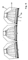
- FIG. 6 shows three side-by-side arranged browning modules, each module has a housing 20 and the frame arrangement according to the invention. It's the reflector 21 in the housing 20 and the first radiation filter 1 and the second radiation filter 2 can be seen.
- Figure 7 shows how the frame assembly with the connecting rod 13 in an opening 22 in Housing 20 is hooked on a swivel mechanism.
- a closure 23 fixes the Frame arrangement in its position (see also Figure 6).
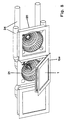
- FIG 8 shows a three-dimensional representation of three tanning modules.
- a Tanning module shown with closed frame arrangement.
- a tanning module shown with opened frame arrangement including tanning lamp, whereby the reflector 21, the first radiation filter 1 and the opaque frame 15a can be seen is.
- a tanning module without radiation filter in the frame arrangement and shown without tanning lamps are equipped with air extraction hoses 24 Mistake.
Landscapes
- Health & Medical Sciences (AREA)
- Engineering & Computer Science (AREA)
- Biomedical Technology (AREA)
- Pathology (AREA)
- Nuclear Medicine, Radiotherapy & Molecular Imaging (AREA)
- Radiology & Medical Imaging (AREA)
- Life Sciences & Earth Sciences (AREA)
- Animal Behavior & Ethology (AREA)
- General Health & Medical Sciences (AREA)
- Public Health (AREA)
- Veterinary Medicine (AREA)
- Filtering Of Dispersed Particles In Gases (AREA)
- Control Of Motors That Do Not Use Commutators (AREA)
- Ultra Sonic Daignosis Equipment (AREA)
- Optical Filters (AREA)
- Apparatus For Radiation Diagnosis (AREA)
- Radiation-Therapy Devices (AREA)
Abstract
Description
Ebenso können die Winkel zwischen zweitem Boden und zweiter oberer Seitenflanke sowie zwischen zweitem Boden und zweiter unterer Seitenflanke gleich 90° sein, wobei die zweite obere und die zweite untere Seitenflanke jeweils mindestens einen Schlitz aufweist und jeweils mindestens ein Bereich der zweiten oberen und der zweiten unteren Seitenflanke im Bereich der Schlitze im Hinblick auf die jeweilige Seitenflanke angewinkelt ist.
Dabei ist jedoch darauf zu achten, dass sich ein Strahlungsfilter leicht in die Federprofile einschieben lassen muss.
Außerdem ist es von Vorteil, wenn der Steg auf halber Höhe zwischen der zweiten oberen und der zweiten unteren Seitenflanke mit dem zweiten Boden verbunden ist.
Der Steg kann aber auch zwischen der zweiten unteren Seitenflanke und der Stufe mit dem unteren zweiten Boden verbunden sein.
Die rechteckige Rahmenanordnung wird dabei idealerweise in das Gehäuse eingehakt. Insbesondere eine Öffnung gemäß Figur 7 im Gehäuse ist geeignet, die erfindungsgemäße Rahmenanordnung derart einzuhaken.
Die rechteckige Rahmenanordnung wird vorzugsweise mittels eines Schnappmechanismus in der Position fixiert.
- Figur 1
- eine rechteckige Rahmenanordnung in dreidimensionaler Ansicht,
- Figur 2
- die Rahmenanordnung aus Figur 1 mit allen verdeckten Linien,
- Figur 3a
- ein erstes Federprofil,
- Figur 3b
- ein zweites Federprofil,
- Figur 4a
- ein weiteres erstes Federprofil,
- Figur 4b
- ein weiteres zweites Federprofil,
- Figur 5
- einen Aufdruck mit undurchsichtigem Randbereich,
- Figur 6
- drei Bräunungsmodule im Schnitt,
- Figur 7
- einen Schwenkmechanismus für die Rahmenanordnung,
- Figur 8
- eine dreidimensionale Darstellung von drei Bräunungsmodulen.
Claims (39)
- Rechteckige Rahmenanordnung mit ein bis zwei scheibenförmigen Strahlungsfiltern zum Abfiltern eines Spektrums eines Bräunungsstrahler, wobei die Rahmenanordnung vier Ecken und vier Seitenkanten aufweist und an einer ersten Seitenkante mindestens ein erstes Federprofil (3a, 3c) und an einer der ersten Seitenkante gegenüberliegenden zweiten Seitenkante mindestens ein zweites Federprofil (3b, 3d) aufweist, wobei das erste Federprofil (3a, 3c) und das zweite Federprofil (3b, 3d) durch mindestens einen Steg (4a, 4b) miteinander verbunden sind und zumindest das erste Federprofil (3a, 3c) U-förmig mit einem ersten Boden (5a), einer ersten oberen Seitenflanke (5b) und einer ersten unteren Seitenflanke (5c) ausgestaltet ist, wobei ein erster Strahlungsfilter (1) in einem ersten Randbereich zwischen dem mindestens einen Steg (4a, 4b) und der ersten unteren Seitenflanke (5c) angeordnet ist.
- Rechteckige Rahmenanordnung nach Anspruch 1, dadurch gekennzeichnet, dass das zweite Federprofil (3b, 3d) U-förmig mit einem zweiten Boden (6a), einer zweiten oberen Seitenflanke (6b) und einer zweiten unteren Seitenflanke (6c) ausgestaltet ist.
- Rechteckige Rahmenanordnung nach einem der Ansprüche 1 bis 2, dadurch gekennzeichnet, dass die Winkel zwischen erstem Boden (5a) und erster oberer Seitenflanke (5b) sowie zwischen erstem Boden (5a) und erster unterer Seitenflanke (5c) kleiner 90° sind.
- Rechteckige Rahmenanordnung nach einem der Ansprüche 2 bis 3, dadurch gekennzeichnet, dass die Winkel zwischen zweitem Boden (6a) und zweiter oberer Seitenflanke (6b) sowie zwischen zweitem Boden (6a) und zweiter unterer Seitenflanke (6c) kleiner 90° sind.
- Rechteckige Rahmenanordnung nach einem der Ansprüche 1 bis 2, dadurch gekennzeichnet, dass die Winkel zwischen erstem Boden (5a) und erster oberer Seitenflanke (5b) sowie zwischen erstem Boden (5a) und erster unterer Seitenflanke (5c) gleich 90° sind, dass die erste obere Seitenflanke (5b) und die erste untere Seitenflanke (5c) jeweils mindestens einen Schlitz (7, 8) aufweisen und dass jeweils mindestens ein Bereich (5e) der ersten oberen Seitenflanke (5b) und ein Bereich (5f) der ersten unteren Seitenflanke (5c) ausgehend vom Ende der Schlitze (7, 8) im Hinblick auf die jeweilige Seitenflanke angewinkelt ist.
- Rechteckige Rahmenanordnung nach einem der Ansprüche 1 bis 2, dadurch gekennzeichnet, dass die Winkel zwischen zweitem Boden (6a) und zweiter oberer Seitenflanke (6b) sowie zwischen zweitem Boden (6a) und zweiter unterer Seitenflanke (6c) gleich 90° sind, dass die zweite obere Seitenflanke (6b) und die zweite untere Seitenflanke (6c) jeweils mindestens einen Schlitz (9, 10) aufweisen und dass jeweils mindestens ein Bereich (6e) der zweiten oberen Seitenflanke (6b) und ein Bereich (5f) der zweiten unteren Seitenflanke (6c) ausgehend vom Ende der Schlitze (9, 10) im Hinblick auf die jeweilige Seitenflanke angewinkelt ist.
- Rechteckige Rahmenanordnung nach einem der Ansprüche 2 oder 6, dadurch gekennzeichnet, dass der zweite Boden (6a) durch eine Stufe (11) in einen oberen zweiten Boden (12a) und einen unteren zweiten Boden (12b) geteilt ist.
- Rechteckige Rahmenanordnung nach Anspruch 7, dadurch gekennzeichnet, dass der obere zweite Boden (12a) und der untere zweite Boden (12b) ungleich breit sind.
- Rechteckige Rahmenanordnung nach einem der Ansprüche 2 bis 3, dadurch gekennzeichnet, dass der erste Strahlungsfilter (1) in einem zweiten Randbereich zwischen dem mindestens einen Steg (4a, 4b) und der zweiten unteren Seitenflanke (6c) angeordnet ist.
- Rechteckige Rahmenanordnung nach einem der Ansprüche 2 bis 9, dadurch gekennzeichnet, dass ein zweiter Strahlungsfilter (2) in einem ersten Randbereich zwischen dem mindestens einen Steg (4a, 4b) und der ersten oberen Seitenflanke (5b) und in einem zweiten Randbereich zwischen dem mindestens einen Steg (4a, 4b) und der zweiten oberen Seitenflanke (6b) angeordnet ist.
- Rechteckige Rahmenanordnung nach einem der Ansprüche 1 bis 10, dadurch gekennzeichnet, dass die Federprofile (3a, 3b, 3c, 3d) aus Federblech gebildet sind
- Rechteckige Rahmenanordnung nach einem der Ansprüche 1 bis 11, dadurch gekennzeichnet, dass zwei erste Federprofile (3a, 3c) an der ersten Seitenkante und zwei zweite Federprofile (3b, 3d) an der zweiten Seitenkante angeordnet sind, wobei jeweils ein Steg (4a, 4b) eines der zwei ersten Federprofile (3a, 3c) mit einem der zwei zweiten Federprofile (3b, 3d) verbindet, und wobei die insgesamt vier Federprofile (3a, 3b, 3c, 3d) jeweils nahe einer der vier Ecken der Rahmenanordnung angeordnet sind und die Stege (4a, 4b) über mindestens eine Verbindungsstange (13) miteinander verbunden sind.
- Rechteckige Rahmenanordnung nach einem der Ansprüche 1 bis 12, dadurch gekennzeichnet, dass der erste Strahlungsfilter (1) einen rechteckigen Umfang aufweist.
- Rechteckige Rahmenanordnung nach einem der Ansprüche 1 bis 13, dadurch gekennzeichnet, dass der erste Strahlungsfilter (1) ein Interferenzfilter ist.
- Rechteckige Rahmenanordnung nach einem der Ansprüche 13 bis 14, dadurch gekennzeichnet, dass der erste Strahlungsfilter (1) eine Breite und eine Länge im Bereich von 210mm bis 300mm aufweist.
- Rechteckige Rahmenanordnung nach Anspruch 15, dadurch gekennzeichnet, dass der erste Strahlungsfilter (1) eine Breite von 220mm und eine Länge von 290mm aufweist.
- Rechteckige Rahmenanordnung nach einem der Ansprüche 10 bis 16, dadurch gekennzeichnet, dass der zweite Strahlungsfilter (2) ein UV-Filter oder ein Infrarotfilter ist.
- Rechteckige Rahmenanordnung nach einem der Ansprüche 10 bis 17, dadurch gekennzeichnet, dass der zweite Strahlungsfilter (2) rechteckig ausgebildet ist.
- Rechteckige Rahmenanordnung nach Anspruch 18, dadurch gekennzeichnet, dass der zweite Strahlungsfilter 82) eine Breite und eine Länge im Bereich von 210mm bis 290mm aufweist.
- Rechteckige Rahmenanordnung nach Anspruch 19, dadurch gekennzeichnet, dass der zweite Strahlungsfilter (2) eine Breite von 220mm und eine Länge von 278mm aufweist
- Rechteckige Rahmenanordnung nach einem der Ansprüche 1 bis 20, dadurch gekennzeichnet, dass der Steg (4a, 4b) auf halber Höhe zwischen der ersten oberen Seitenflanke (5b) und der ersten unteren Seitenflanke (5c) mit dem ersten Boden (5a) verbunden ist.
- Rechteckige Rahmenanordnung nach einem der Ansprüche 1 bis 6, dadurch gekennzeichnet, dass der Steg (4a, 4b) auf halber Höhe zwischen der zweiten oberen Seitenflanke (6b) und der zweiten unteren Seitenflanke (6c) mit dem zweiten Boden (6a) verbunden ist.
- Rechteckige Rahmenanordnung nach einem der Ansprüche 7 bis 22, dadurch gekennzeichnet, dass der Steg (4a, 4b) zwischen der zweiten oberen Seitenflanke (6b) und der Stufe (11) mit dem oberen zweiten Boden (12a) verbunden ist.
- Rechteckige Rahmenanordnung nach einem der Ansprüche 7 bis 23, dadurch gekennzeichnet, dass der Steg (4a, 4b) zwischen der zweiten unteren Seitenflanke (6c) und der Stufe (11) mit dem unteren zweiten Boden (12b) verbunden ist.
- Rechteckige Rahmenanordnung nach einem der Ansprüche 1 bis 24, dadurch gekennzeichnet, dass die oberen Seitenflanken (5b, 6b) und/oder die unteren Seitenflanken (5c, 6c) einen Knick (5g, 5f, 6g, 6f) aufweisen.
- Rechteckige Rahmenanordnung nach einem der Ansprüche 1 bis 25, dadurch gekennzeichnet, dass an den Seitenkanten der Rahmenanordnung, an denen kein Federprofil vorhanden ist, jeweils eine Rutschsicherung für den ersten Strahlungsfilter (1) angeordnet ist.
- Rechteckige Rahmenanordnung nach einem der Ansprüche 10 bis 26, dadurch gekennzeichnet, dass an den Seitenkanten der Rahmenanordnung, an denen kein Federprofil vorhanden ist, jeweils eine Rutschsicherung für den zweiten Strahlungsfilter (2) angeordnet ist.
- Rechteckige Rahmenanordnung nach einem der Ansprüche 1 bis 27, dadurch gekennzeichnet, dass der erste Strahlungsfilter (1) auf seiner dem zweiten Strahlungsfilter (2) abgewandten Seite einen Aufdruck oder Aufkleber (15) aufweist.
- Rechteckige Rahmenanordnung nach Anspruch 28, dadurch gekennzeichnet, dass der Aufdruck oder Aufkleber (15) einen undurchsichtigen Randbereich (15a) aufweist.
- Bräunungsmodul mit einem Gehäuse (20), einem im oder am Gehäuse (20) angeordneten, dreidimensionalen Reflektor (21) sowie einer rechteckigen Rahmenanordnung nach einem der Ansprüche 1 bis 29 an einer Seite des Gehäuses (20), wobei der erste Strahlungsfilter (1) die Strahlungsaustrittsfläche des Reflektors (21) überdeckt, wobei die obere erste Seitenflanke (5b) und die obere zweite Seitenflanke (6b) des Federprofils (3a, 3b, 3c, 3d) dem Reflektor (21) zugewandt sind, während die untere erste Seitenflanke (5c) und die untere zweite Seitenflanke (6c) des Federprofils (3a, 3b, 3c, 3d) vom Reflektor (21) abgewandt sind.
- Bräunungsmodul nach Anspruch 30, dadurch gekennzeichnet, dass die rechteckige Rahmenanordnung über einen Schwenkmechanismus vom Gehäuse (20) lösbar ist.
- Bräunungsmodul nach Anspruch 31, dadurch gekennzeichnet, dass die rechteckige Rahmenanordnung in das Gehäuse (20) eingehakt ist.
- Bräunungsmodul nach Anspruch 31, dadurch gekennzeichnet, dass die rechteckige Rahmenanordnung in eine Öffnung (22) gemäß Figur 7 im Gehäuse (20) eingehakt ist.
- Bräunungsmodul nach einem der Ansprüche 28 bis 31, dadurch gekennzeichnet, dass die rechteckige Rahmenanordnung mittels eines Schnappmechanismus (23) in der Position fixiert wird.
- Bräunungsmodul nach einem der Ansprüche 30 bis 34, dadurch gekennzeichnet, dass ein Umfang des Reflektors (21) parallel zur Strahlungsaustrittsfläche einen Kreis, eine Ellipse, ein Rechteck oder ein Vieleck beschreibt.
- Bräunungsmodul nach Anspruch 35, dadurch gekennzeichnet, dass der Reflektor (21) aus Facetten gebildet ist und der Umfang des Reflektors (21) parallel zur Strahlungsaustrittsfläche ein Vieleck mit zwölf Ecken beschreibt.
- Bräunungsmodul nach Anspruch 36, dadurch gekennzeichnet, dass der Reflektor (21) eine Höhe von 90mm bis 95mm, insbesondere von 93,6mm, und das Zwölfeck in der Ebene der Strahlungsaustrittsfläche einen maximalen Durchmesser ( von Ecke zu Ecke ) im Bereich von 210mm bis 230mm, insbesondere von 210mm, aufweist.
- Bräunungsmodul nach Anspruch 36, dadurch gekennzeichnet, dass der Reflektor (21) eine Höhe im Bereich von 110mm bis 125mm, insbesondere von 118,7mm, und das Zwölfeck in der Ebene der Strahlungsaustrittsfläche einen maximalen Durchmesser ( von Ecke zu Ecke ) im Bereich von 170mm bis 200mm, insbesondere von 184mm, aufweist.
- Bräunungsmodul nach Anspruch 36, dadurch gekennzeichnet, dass der Reflektor (21) eine Höhe im Bereich von 75mm bis 90mm, insbesondere von 83,3mm, und das Zwölfeck in der Ebene der Strahlungsaustrittsfläche einen maximalen Durchmesser ( von Ecke zu Ecke ) im Bereich von 205mm bis 235mm, insbesondere von 220mm, aufweist.
Priority Applications (1)
| Application Number | Priority Date | Filing Date | Title |
|---|---|---|---|
| DK02022556T DK1306107T3 (da) | 2001-10-24 | 2002-10-08 | Rektangulær rammeindretning med et til to skiveformede strålingsfiltre og bruningsmodul |
Applications Claiming Priority (2)
| Application Number | Priority Date | Filing Date | Title |
|---|---|---|---|
| DE10151841 | 2001-10-24 | ||
| DE10151841A DE10151841B4 (de) | 2001-10-24 | 2001-10-24 | Rechteckige Rahmenanordnung mit ein bis zwei scheibenförmigen Strahlungsfiltern und Bräunungsmodul |
Publications (3)
| Publication Number | Publication Date |
|---|---|
| EP1306107A2 true EP1306107A2 (de) | 2003-05-02 |
| EP1306107A3 EP1306107A3 (de) | 2003-12-10 |
| EP1306107B1 EP1306107B1 (de) | 2005-06-01 |
Family
ID=7703166
Family Applications (1)
| Application Number | Title | Priority Date | Filing Date |
|---|---|---|---|
| EP02022556A Expired - Lifetime EP1306107B1 (de) | 2001-10-24 | 2002-10-08 | Rechteckige Rahmenanordnung mit ein bis zwei scheibenförmigen Strahlungsfiltern und Bräunungsmodul |
Country Status (6)
| Country | Link |
|---|---|
| US (1) | US6918923B2 (de) |
| EP (1) | EP1306107B1 (de) |
| AT (1) | ATE296667T1 (de) |
| DE (2) | DE10151841B4 (de) |
| DK (1) | DK1306107T3 (de) |
| ES (1) | ES2240629T3 (de) |
Cited By (1)
| Publication number | Priority date | Publication date | Assignee | Title |
|---|---|---|---|---|
| EP1916017A1 (de) * | 2006-10-27 | 2008-04-30 | Tecnova di Ciccarello Spitaleri Angelo | Vorrichtung zur Halterung von Filtern für Bräunungslampen |
Families Citing this family (2)
| Publication number | Priority date | Publication date | Assignee | Title |
|---|---|---|---|---|
| CN101469841B (zh) * | 2007-12-28 | 2011-03-30 | 富士迈半导体精密工业(上海)有限公司 | 照明装置 |
| US20240366957A1 (en) * | 2023-05-05 | 2024-11-07 | Randy Mersky | Customizable tanning apparatus |
Citations (5)
| Publication number | Priority date | Publication date | Assignee | Title |
|---|---|---|---|---|
| DE2941467A1 (de) | 1979-10-12 | 1981-04-23 | Hans Robert Dr. Innsbruck Sellmeier | Braeunungsgeraet fuer direktpigmentierung |
| DE3927695C2 (de) | 1989-08-22 | 1995-04-20 | Kratz Josef Gmbh | Bräunungsgerät |
| DE3631427C2 (de) | 1985-09-17 | 1996-02-15 | Philips Electronics Nv | Bestrahlungsgerät |
| DE19516603A1 (de) | 1995-05-09 | 1996-11-14 | Imab Stiftung | Niederdruckgesichtsfeld für Bräunungsgeräte |
| DE4037483C2 (de) | 1990-11-24 | 2000-06-29 | Uwe Unterwasser Electric Gmbh | UV-Bestrahlungsgerät, insbesondere an einer Bräunnungsliege |
Family Cites Families (8)
| Publication number | Priority date | Publication date | Assignee | Title |
|---|---|---|---|---|
| US5034866A (en) * | 1989-12-28 | 1991-07-23 | Altman Stage Lighting Co., Inc. | Multilamp strip light luminaire system |
| US5091835A (en) * | 1991-02-25 | 1992-02-25 | Leonetti Company | High intensity lamp with improved air flow ventilation |
| US5620478A (en) * | 1992-10-20 | 1997-04-15 | Esc Medical Systems Ltd. | Method and apparatus for therapeutic electromagnetic treatment |
| DE29705097U1 (de) * | 1997-03-05 | 1997-12-11 | Schättgen, Horst, 51069 Köln | Farbfiltervorsatz mit Farbfilterwechseleinrichtung |
| US6406509B1 (en) * | 1999-07-01 | 2002-06-18 | 3M Innovative Properties Company | Extruded profile filter framing |
| DE20107299U1 (de) * | 2001-04-23 | 2001-08-09 | Arnold & Richter Cine Technik GmbH & Co Betriebs KG, 80799 München | Scheinwerfer mit einem Gehäuse mit Halteklauen |
| DE20117228U1 (de) * | 2001-10-24 | 2002-01-17 | Heraeus Noblelight Gmbh, 63450 Hanau | Rechteckige Rahmenanordnung mit ein bis zwei scheibenförmigen Strahlungsfiltern und Bräunungsmodul |
| DE10151850A1 (de) * | 2001-10-24 | 2003-05-15 | Heraeus Noblelight Gmbh | Bräunungsmodul mit einem Gehäuse |
-
2001
- 2001-10-24 DE DE10151841A patent/DE10151841B4/de not_active Expired - Fee Related
-
2002
- 2002-09-30 US US10/261,240 patent/US6918923B2/en not_active Expired - Fee Related
- 2002-10-08 DE DE50203251T patent/DE50203251D1/de not_active Expired - Fee Related
- 2002-10-08 ES ES02022556T patent/ES2240629T3/es not_active Expired - Lifetime
- 2002-10-08 EP EP02022556A patent/EP1306107B1/de not_active Expired - Lifetime
- 2002-10-08 DK DK02022556T patent/DK1306107T3/da active
- 2002-10-08 AT AT02022556T patent/ATE296667T1/de not_active IP Right Cessation
Patent Citations (5)
| Publication number | Priority date | Publication date | Assignee | Title |
|---|---|---|---|---|
| DE2941467A1 (de) | 1979-10-12 | 1981-04-23 | Hans Robert Dr. Innsbruck Sellmeier | Braeunungsgeraet fuer direktpigmentierung |
| DE3631427C2 (de) | 1985-09-17 | 1996-02-15 | Philips Electronics Nv | Bestrahlungsgerät |
| DE3927695C2 (de) | 1989-08-22 | 1995-04-20 | Kratz Josef Gmbh | Bräunungsgerät |
| DE4037483C2 (de) | 1990-11-24 | 2000-06-29 | Uwe Unterwasser Electric Gmbh | UV-Bestrahlungsgerät, insbesondere an einer Bräunnungsliege |
| DE19516603A1 (de) | 1995-05-09 | 1996-11-14 | Imab Stiftung | Niederdruckgesichtsfeld für Bräunungsgeräte |
Cited By (1)
| Publication number | Priority date | Publication date | Assignee | Title |
|---|---|---|---|---|
| EP1916017A1 (de) * | 2006-10-27 | 2008-04-30 | Tecnova di Ciccarello Spitaleri Angelo | Vorrichtung zur Halterung von Filtern für Bräunungslampen |
Also Published As
| Publication number | Publication date |
|---|---|
| ES2240629T3 (es) | 2005-10-16 |
| EP1306107B1 (de) | 2005-06-01 |
| US6918923B2 (en) | 2005-07-19 |
| ATE296667T1 (de) | 2005-06-15 |
| EP1306107A3 (de) | 2003-12-10 |
| DE10151841A1 (de) | 2003-05-15 |
| DE10151841B4 (de) | 2007-02-08 |
| DK1306107T3 (da) | 2005-08-01 |
| US20030078636A1 (en) | 2003-04-24 |
| DE50203251D1 (de) | 2005-07-07 |
Similar Documents
| Publication | Publication Date | Title |
|---|---|---|
| DE102011085289A1 (de) | Lichtbeeinflussungselement zur Beeinflussung der Lichtabgabe von im Wesentlichen punktförmigen Lichtquellen sowie Leuchte mit Lichtbeeinflussungselement | |
| EP1306107B1 (de) | Rechteckige Rahmenanordnung mit ein bis zwei scheibenförmigen Strahlungsfiltern und Bräunungsmodul | |
| WO2012041792A1 (de) | Leuchtmodulanordnung mit einer led auf einer platine | |
| EP0116909B1 (de) | Halterung einer absenkbaren Leuchtenabdeckung | |
| EP1314928A1 (de) | Lichtverteiler, Leuchteinrichtung mit mindestens einem Lichtverteiler und Verfahren zur Herstellung eines Lichtverteilers | |
| WO1999045313A2 (de) | Vorrichtung zur ausbildung aktiv leuchtender leuchtwegesysteme | |
| EP0645105B1 (de) | Tisch und Tischsystem | |
| EP2295851A2 (de) | Lichtbeeinflussungselement | |
| EP2175188B1 (de) | Leuchte | |
| DE3103175C2 (de) | Rückfahrscheinwerfer für Kraftfahrzeuge | |
| EP3385608A1 (de) | Beleuchtungsvorrichtung für fahrzeuge | |
| DE20117228U1 (de) | Rechteckige Rahmenanordnung mit ein bis zwei scheibenförmigen Strahlungsfiltern und Bräunungsmodul | |
| EP1257005A1 (de) | Klemmvorrichtung zum Befestigen von Platten und insbesondere transparenten Glasscheiben | |
| EP3446031B1 (de) | Schaltschrankleuchte mit verstellbarer leuchtmittelplatine | |
| DE2947719C2 (de) | Retroreflektorplatte | |
| DE2912766B1 (de) | Tischleuchte für röhrenförmige Leuchtstofflampen | |
| DE2501790C3 (de) | Strahlerleuchte | |
| DE20121495U1 (de) | Mastleuchte | |
| DE102018123128B4 (de) | Leuchte mit plattenförmigem Lichtleitelement | |
| DE4102199A1 (de) | Lichtdiffusor | |
| DE19859279C2 (de) | Anordnung zum Anbringen einer Kennzeichnungskarte | |
| DE102005021694B4 (de) | Kraftfahrzeugleuchte mit einem Reflektor, umfassend erste Reflektorsegmente für erzeugtes Licht und zweite Reflektorsegmente für einfallendes Licht | |
| EP1843082B1 (de) | Deckenleuchte, insbesondere zur Verwendung in einem Flur | |
| EP0503126B1 (de) | Lampenfuss | |
| EP0316532A2 (de) | Beleuchtungsvorrichtung |
Legal Events
| Date | Code | Title | Description |
|---|---|---|---|
| PUAI | Public reference made under article 153(3) epc to a published international application that has entered the european phase |
Free format text: ORIGINAL CODE: 0009012 |
|
| 17P | Request for examination filed |
Effective date: 20021017 |
|
| AK | Designated contracting states |
Designated state(s): AT BE BG CH CY CZ DE DK EE ES FI FR GB GR IE IT LI LU MC NL PT SE SK TR |
|
| AX | Request for extension of the european patent |
Extension state: AL LT LV MK RO SI |
|
| PUAL | Search report despatched |
Free format text: ORIGINAL CODE: 0009013 |
|
| AK | Designated contracting states |
Kind code of ref document: A3 Designated state(s): AT BE BG CH CY CZ DE DK EE ES FI FR GB GR IE IT LI LU MC NL PT SE SK TR |
|
| AX | Request for extension of the european patent |
Extension state: AL LT LV MK RO SI |
|
| AKX | Designation fees paid |
Designated state(s): AT BE BG CH CY CZ DE DK EE ES FI FR GB GR IE IT LI LU MC NL PT SE SK TR |
|
| GRAP | Despatch of communication of intention to grant a patent |
Free format text: ORIGINAL CODE: EPIDOSNIGR1 |
|
| GRAS | Grant fee paid |
Free format text: ORIGINAL CODE: EPIDOSNIGR3 |
|
| GRAA | (expected) grant |
Free format text: ORIGINAL CODE: 0009210 |
|
| AK | Designated contracting states |
Kind code of ref document: B1 Designated state(s): AT BE BG CH CY CZ DE DK EE ES FI FR GB GR IE IT LI LU MC NL PT SE SK TR |
|
| PG25 | Lapsed in a contracting state [announced via postgrant information from national office to epo] |
Ref country code: EE Free format text: LAPSE BECAUSE OF FAILURE TO SUBMIT A TRANSLATION OF THE DESCRIPTION OR TO PAY THE FEE WITHIN THE PRESCRIBED TIME-LIMIT Effective date: 20050601 Ref country code: IE Free format text: LAPSE BECAUSE OF FAILURE TO SUBMIT A TRANSLATION OF THE DESCRIPTION OR TO PAY THE FEE WITHIN THE PRESCRIBED TIME-LIMIT Effective date: 20050601 Ref country code: TR Free format text: LAPSE BECAUSE OF FAILURE TO SUBMIT A TRANSLATION OF THE DESCRIPTION OR TO PAY THE FEE WITHIN THE PRESCRIBED TIME-LIMIT Effective date: 20050601 Ref country code: SK Free format text: LAPSE BECAUSE OF FAILURE TO SUBMIT A TRANSLATION OF THE DESCRIPTION OR TO PAY THE FEE WITHIN THE PRESCRIBED TIME-LIMIT Effective date: 20050601 Ref country code: FI Free format text: LAPSE BECAUSE OF FAILURE TO SUBMIT A TRANSLATION OF THE DESCRIPTION OR TO PAY THE FEE WITHIN THE PRESCRIBED TIME-LIMIT Effective date: 20050601 Ref country code: CZ Free format text: LAPSE BECAUSE OF FAILURE TO SUBMIT A TRANSLATION OF THE DESCRIPTION OR TO PAY THE FEE WITHIN THE PRESCRIBED TIME-LIMIT Effective date: 20050601 |
|
| REG | Reference to a national code |
Ref country code: GB Ref legal event code: FG4D Free format text: NOT ENGLISH |
|
| REG | Reference to a national code |
Ref country code: CH Ref legal event code: EP |
|
| REF | Corresponds to: |
Ref document number: 50203251 Country of ref document: DE Date of ref document: 20050707 Kind code of ref document: P |
|
| REG | Reference to a national code |
Ref country code: IE Ref legal event code: FG4D Free format text: LANGUAGE OF EP DOCUMENT: GERMAN |
|
| REG | Reference to a national code |
Ref country code: DK Ref legal event code: T3 |
|
| REG | Reference to a national code |
Ref country code: SE Ref legal event code: TRGR |
|
| PG25 | Lapsed in a contracting state [announced via postgrant information from national office to epo] |
Ref country code: GR Free format text: LAPSE BECAUSE OF FAILURE TO SUBMIT A TRANSLATION OF THE DESCRIPTION OR TO PAY THE FEE WITHIN THE PRESCRIBED TIME-LIMIT Effective date: 20050901 Ref country code: BG Free format text: LAPSE BECAUSE OF FAILURE TO SUBMIT A TRANSLATION OF THE DESCRIPTION OR TO PAY THE FEE WITHIN THE PRESCRIBED TIME-LIMIT Effective date: 20050901 |
|
| GBT | Gb: translation of ep patent filed (gb section 77(6)(a)/1977) |
Effective date: 20050902 |
|
| PG25 | Lapsed in a contracting state [announced via postgrant information from national office to epo] |
Ref country code: AT Free format text: LAPSE BECAUSE OF NON-PAYMENT OF DUE FEES Effective date: 20051008 Ref country code: CY Free format text: LAPSE BECAUSE OF FAILURE TO SUBMIT A TRANSLATION OF THE DESCRIPTION OR TO PAY THE FEE WITHIN THE PRESCRIBED TIME-LIMIT Effective date: 20051008 |
|
| REG | Reference to a national code |
Ref country code: ES Ref legal event code: FG2A Ref document number: 2240629 Country of ref document: ES Kind code of ref document: T3 |
|
| PG25 | Lapsed in a contracting state [announced via postgrant information from national office to epo] |
Ref country code: LU Free format text: LAPSE BECAUSE OF NON-PAYMENT OF DUE FEES Effective date: 20051031 Ref country code: MC Free format text: LAPSE BECAUSE OF NON-PAYMENT OF DUE FEES Effective date: 20051031 |
|
| PG25 | Lapsed in a contracting state [announced via postgrant information from national office to epo] |
Ref country code: PT Free format text: LAPSE BECAUSE OF FAILURE TO SUBMIT A TRANSLATION OF THE DESCRIPTION OR TO PAY THE FEE WITHIN THE PRESCRIBED TIME-LIMIT Effective date: 20051103 |
|
| REG | Reference to a national code |
Ref country code: IE Ref legal event code: FD4D |
|
| PLBE | No opposition filed within time limit |
Free format text: ORIGINAL CODE: 0009261 |
|
| STAA | Information on the status of an ep patent application or granted ep patent |
Free format text: STATUS: NO OPPOSITION FILED WITHIN TIME LIMIT |
|
| 26N | No opposition filed |
Effective date: 20060302 |
|
| EN | Fr: translation not filed | ||
| PG25 | Lapsed in a contracting state [announced via postgrant information from national office to epo] |
Ref country code: CH Free format text: LAPSE BECAUSE OF NON-PAYMENT OF DUE FEES Effective date: 20061031 Ref country code: LI Free format text: LAPSE BECAUSE OF NON-PAYMENT OF DUE FEES Effective date: 20061031 |
|
| REG | Reference to a national code |
Ref country code: CH Ref legal event code: PL |
|
| PG25 | Lapsed in a contracting state [announced via postgrant information from national office to epo] |
Ref country code: FR Free format text: LAPSE BECAUSE OF NON-PAYMENT OF DUE FEES Effective date: 20051031 |
|
| PG25 | Lapsed in a contracting state [announced via postgrant information from national office to epo] |
Ref country code: FR Free format text: LAPSE BECAUSE OF NON-PAYMENT OF DUE FEES Effective date: 20050601 |
|
| PGFP | Annual fee paid to national office [announced via postgrant information from national office to epo] |
Ref country code: NL Payment date: 20081015 Year of fee payment: 7 |
|
| PGFP | Annual fee paid to national office [announced via postgrant information from national office to epo] |
Ref country code: DE Payment date: 20081022 Year of fee payment: 7 Ref country code: DK Payment date: 20081015 Year of fee payment: 7 |
|
| PGFP | Annual fee paid to national office [announced via postgrant information from national office to epo] |
Ref country code: ES Payment date: 20081027 Year of fee payment: 7 |
|
| PGFP | Annual fee paid to national office [announced via postgrant information from national office to epo] |
Ref country code: SE Payment date: 20081014 Year of fee payment: 7 Ref country code: IT Payment date: 20081022 Year of fee payment: 7 Ref country code: BE Payment date: 20081120 Year of fee payment: 7 |
|
| PGFP | Annual fee paid to national office [announced via postgrant information from national office to epo] |
Ref country code: GB Payment date: 20081021 Year of fee payment: 7 |
|
| BERE | Be: lapsed |
Owner name: *HERAEUS NOBLELIGHT G.M.B.H. Effective date: 20091031 |
|
| REG | Reference to a national code |
Ref country code: NL Ref legal event code: V1 Effective date: 20100501 |
|
| EUG | Se: european patent has lapsed | ||
| REG | Reference to a national code |
Ref country code: DK Ref legal event code: EBP |
|
| PG25 | Lapsed in a contracting state [announced via postgrant information from national office to epo] |
Ref country code: DE Free format text: LAPSE BECAUSE OF NON-PAYMENT OF DUE FEES Effective date: 20100501 Ref country code: NL Free format text: LAPSE BECAUSE OF NON-PAYMENT OF DUE FEES Effective date: 20100501 |
|
| PG25 | Lapsed in a contracting state [announced via postgrant information from national office to epo] |
Ref country code: BE Free format text: LAPSE BECAUSE OF NON-PAYMENT OF DUE FEES Effective date: 20091031 |
|
| PG25 | Lapsed in a contracting state [announced via postgrant information from national office to epo] |
Ref country code: GB Free format text: LAPSE BECAUSE OF NON-PAYMENT OF DUE FEES Effective date: 20091008 |
|
| PG25 | Lapsed in a contracting state [announced via postgrant information from national office to epo] |
Ref country code: DK Free format text: LAPSE BECAUSE OF NON-PAYMENT OF DUE FEES Effective date: 20091031 |
|
| PG25 | Lapsed in a contracting state [announced via postgrant information from national office to epo] |
Ref country code: IT Free format text: LAPSE BECAUSE OF NON-PAYMENT OF DUE FEES Effective date: 20091008 |
|
| REG | Reference to a national code |
Ref country code: ES Ref legal event code: FD2A Effective date: 20110401 |
|
| PG25 | Lapsed in a contracting state [announced via postgrant information from national office to epo] |
Ref country code: SE Free format text: LAPSE BECAUSE OF NON-PAYMENT OF DUE FEES Effective date: 20091009 |
|
| PG25 | Lapsed in a contracting state [announced via postgrant information from national office to epo] |
Ref country code: ES Free format text: LAPSE BECAUSE OF NON-PAYMENT OF DUE FEES Effective date: 20110322 |
|
| PG25 | Lapsed in a contracting state [announced via postgrant information from national office to epo] |
Ref country code: ES Free format text: LAPSE BECAUSE OF NON-PAYMENT OF DUE FEES Effective date: 20091009 |