EP1306132A2 - Dispositif de connection de lignes d'alimentation pour laboratoire - Google Patents
Dispositif de connection de lignes d'alimentation pour laboratoire Download PDFInfo
- Publication number
- EP1306132A2 EP1306132A2 EP02021949A EP02021949A EP1306132A2 EP 1306132 A2 EP1306132 A2 EP 1306132A2 EP 02021949 A EP02021949 A EP 02021949A EP 02021949 A EP02021949 A EP 02021949A EP 1306132 A2 EP1306132 A2 EP 1306132A2
- Authority
- EP
- European Patent Office
- Prior art keywords
- cell according
- media cell
- installation
- elements
- lines
- Prior art date
- Legal status (The legal status is an assumption and is not a legal conclusion. Google has not performed a legal analysis and makes no representation as to the accuracy of the status listed.)
- Withdrawn
Links
- 238000009434 installation Methods 0.000 claims abstract description 77
- XLYOFNOQVPJJNP-UHFFFAOYSA-N water Substances O XLYOFNOQVPJJNP-UHFFFAOYSA-N 0.000 claims abstract description 13
- 230000005611 electricity Effects 0.000 claims abstract description 7
- 238000007789 sealing Methods 0.000 claims description 12
- 239000007789 gas Substances 0.000 description 12
- 239000002351 wastewater Substances 0.000 description 6
- 230000008901 benefit Effects 0.000 description 5
- 229920003023 plastic Polymers 0.000 description 4
- 238000012360 testing method Methods 0.000 description 4
- 229910052782 aluminium Inorganic materials 0.000 description 3
- XAGFODPZIPBFFR-UHFFFAOYSA-N aluminium Chemical compound [Al] XAGFODPZIPBFFR-UHFFFAOYSA-N 0.000 description 3
- 229910052751 metal Inorganic materials 0.000 description 3
- 239000002184 metal Substances 0.000 description 3
- 238000000034 method Methods 0.000 description 3
- 238000004140 cleaning Methods 0.000 description 2
- 238000011109 contamination Methods 0.000 description 2
- 230000002349 favourable effect Effects 0.000 description 2
- 238000009428 plumbing Methods 0.000 description 2
- 230000001681 protective effect Effects 0.000 description 2
- 238000003860 storage Methods 0.000 description 2
- 229910000838 Al alloy Inorganic materials 0.000 description 1
- VVQNEPGJFQJSBK-UHFFFAOYSA-N Methyl methacrylate Chemical compound COC(=O)C(C)=C VVQNEPGJFQJSBK-UHFFFAOYSA-N 0.000 description 1
- 229920005372 Plexiglas® Polymers 0.000 description 1
- 230000008859 change Effects 0.000 description 1
- 238000006243 chemical reaction Methods 0.000 description 1
- 230000008878 coupling Effects 0.000 description 1
- 238000010168 coupling process Methods 0.000 description 1
- 238000005859 coupling reaction Methods 0.000 description 1
- 238000013461 design Methods 0.000 description 1
- 238000010616 electrical installation Methods 0.000 description 1
- 238000002474 experimental method Methods 0.000 description 1
- 238000004519 manufacturing process Methods 0.000 description 1
- 230000008569 process Effects 0.000 description 1
- 238000012545 processing Methods 0.000 description 1
- 238000010079 rubber tapping Methods 0.000 description 1
- 238000000926 separation method Methods 0.000 description 1
- 230000009897 systematic effect Effects 0.000 description 1
- 230000007704 transition Effects 0.000 description 1
Images


Classifications
-
- B—PERFORMING OPERATIONS; TRANSPORTING
- B01—PHYSICAL OR CHEMICAL PROCESSES OR APPARATUS IN GENERAL
- B01L—CHEMICAL OR PHYSICAL LABORATORY APPARATUS FOR GENERAL USE
- B01L9/00—Supporting devices; Holding devices
- B01L9/02—Laboratory benches or tables; Fittings therefor
Definitions
- the invention relates to a media cell for a laboratory or the like Installation connections for gas and / or air and / or water and / or electricity and / or data lines.
- Energy cells or media cells of the type mentioned are in Laboratory facilities behind a one-sided laboratory table or between two opposite laboratory tables arranged and serve to Supply and discharge energy and media.
- a So-called installation channel is provided, in which connection elements and controls are permanently installed in a mixed arrangement.
- the lines leading to and from experimental setups and devices are usually placed on the laboratory table. If for a try or the like different lines for the supply and discharge of gas, air (compressed air, vacuum), electricity, water and data there is often a tangled position of these lines, which is not is more clear.
- the set-ups for the analyzes and tests often have to be rebuilt in today's laboratories. If for Energy or media not enough connections on the outside of the installation duct complex conversions must be made are often the job of an installer requires.
- the invention has for its object a media cell of the beginning mentioned type to create a clear line permitted and in particular also the possibility for a laboratory technician offers, connecting elements and / or controls according to his Arrange wishes.
- connection elements and / or control elements has connectable to distributor connections by means of connecting elements are.
- the invention enables a laboratory technician to arrange the Connection elements and controls that he chooses for the to be carried out Analysis or trial to be carried out for the cheapest holds. This makes it possible to route the necessary cables that the clarity is not lost.
- the use of a wall-shaped installation element allows good use of space, so that the table depth is usually at an ergonomically favorable level can be reduced by about 0.75m.
- the installation lines and / or the distributor connections in several rows one above the other are arranged. This results in a very good use of space, without losing table depth. Because the rows are natural not all are equally accessible, it makes sense if permanent or connecting elements or operating elements that can only rarely be changed on the more distant rows, i.e. the top rows, are attached, while the frequently changing connection elements or controls on the lower row, which is within easy reach be attached.
- the installation element on the user side with partially openable and / or removable closure parts is provided. That way they are Installation lines and manifold connections easily accessible, however you can behind the locking parts during a test be hidden so that they are protected against damage and / or Contamination are protected.
- connection elements and / or controls that do not require cable lengths to accommodate the installation element, so that the clarity the establishment of an analysis or experiment is further improved. It is further advantageous if the joints have deformable sealing elements are provided. This eliminates the risk of contamination reduced and cleaning easier.
- connection elements and / or control elements combined into modules are.
- Such modules can be easily assembled and also with connect the corresponding distributor connections.
- connection elements and / or control elements are provided with connecting cables on the back. These lines can then be largely within the installation element accommodate.
- Such modules also have the advantage that they can be produced inexpensively in large quantities.
- one module each contains only one type of connection element or control element. Thereby can a laboratory technician combine the connecting elements and Control elements in the number and arrangement desired by him choose.
- the installation element on the user side with a table height to the outside projecting connection bracket is provided.
- a laboratory table can be set up or put on.
- connection console is provided with a water drain pipe.
- a wastewater basin on the console over the drain pipe with a drain or a waste water tank or the like is connected.
- connection console has a vertical and a horizontal section, the merge into one another over a rounded section.
- the installation element with holders for console-like holders for additional devices is equipped. This gives the advantage that these additional devices can be attached to the installation element, so that no shelf space on the laboratory table is required for these additional devices becomes.
- these additional devices are in a further embodiment stationary between openable and / or removable closure parts arranged closure parts provided that designed as recordings are.
- At least a stationary closure part is designed as a profile rail, the at least one, preferably running in the horizontal direction, preferably has an undercut groove.
- connection elements and / or control elements can be groove attach very easily, keeping the position in the longitudinal direction the groove is changeable.
- At least a stationary closure part is designed as a console for User side protrudes from the installation element.
- This console can be used in a standing or hanging arrangement record, for example a measuring device or a monitor Computer.
- the consoles can also be designed in this way be that they have connection elements or controls in addition be able to record.
- At least one is stationary Closure part with a spaced from its front surface preferably horizontally directed rod.
- This Pole can be used as a recording in very different ways become.
- the connecting elements and / or attached to the rod Control elements and / or additional devices such as tripod holders or The like can be done in a simple manner with clip elements on the rod be attached. Their position in the longitudinal direction of the bar is simple variable.
- Poles attached to substructures and / or cabinet structures can, for example, on drawers or doors of the Serve substructure or on wall units as handle strips. About that in addition, they are also used as brackets for consoles or the like used.
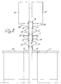
- the most important component of the laboratory equipment shown in FIG. 1 is a media cell made of a wall-shaped, vertically aligned Installation element 20, the one above the height of a table top 21 Laboratory tables with installation lines and distributor connections is equipped, as explained in particular with reference to FIGS. 3 to 5 becomes.
- the installation element 20 has two side stands Metal pipes or metal profiles are.
- the installation lines and distributor connections are arranged within the contour of the side stand, on their narrow sides facing the user side, i.e. that of Table top 21 facing narrow sides, locking parts 22, 23, 24, 25, 26 are attached. This is in a grid dimension arranged, alternating successive stationary closure parts 22, 24, 26 and interposed openable closure parts 23, 25.
- the stationary closure parts are, for example, with screws attached to the front of the side stand.
- the openable locking parts 23 are horizontal in the embodiment of FIG. 1 Swiveling axes foldable.
- the swivel axes are by means of Bearing blocks formed on the narrow sides of the side stand are attached, for example, by means of screws.
- By opening the locking parts 23, 25 are the one behind it within the installation element 20 horizontal installation lines and distributor connections good accessible so that connection elements and / or controls in can be connected in a simple way, like that later will be explained.
- the stationary closure element 22 has a flush with the table top 21 extending section and a vertically aligned thereto Section that merge into one another via a curve.
- the vertical Section of the closure part 22 is aligned with the openable closure parts 23, 25 (when in the closed position) and the stationary locking parts 24, 26.
- the stationary locking parts 24, 26 serve as support elements for connection elements and / or control elements, as will be explained later. In the embodiment 1, they are provided with brackets 27, 28, the Support arms are attached to the closure parts 24, 26.
- the entire space is not above the table top for installation lines and distributor connections exploited.
- the side panels up to the ceiling of a laboratory room, i.e. even more locking parts to be provided, i.e. both openable and stationary locking parts.
- the installation space is above the usage area covered by a traverse 29, which is between the side stands extends.
- the installation element 20 arranged in the area of the back of a laboratory table and is only used on one side.
- the installation element 20 can also be arranged between two laboratory tables, so that it can be used from both sides, i.e. has two user pages.
- the two user sides are mirror images designed, i.e. the closure parts 22, 23, 24, 25 and 26 correspondingly opposite closure parts 22 ', 23', 24 ', 25' and 26 ' arranged.
- they are mirror images of each other Consoles 27, 27 'and 28, 28' are provided. This is of course not necessary because the two sides of the installation element can be equipped differently.
- the openable closure elements 23, 23 'and 25, 25' offer the advantage that when they are are opened at the same time, a hatch is created by means of which Items from the area of the table top 21 to the area of the Table top 21 'or vice versa can be passed. As well can pass lines through the column from side to side be performed.
- Fig. 3 is the arrangement of installation lines and manifold connections shown schematically within an installation element 20.
- the installation lines are in several horizontal, one above the other arranged rows 31, 32, 33, 34, 35 and 36 arranged.
- the procedure is such that these installation lines and distributor connections in the most accessible rows 31, 32 are arranged on which the most common is a change of connections must take place during analyzes or tests.
- These are, for example electrical distributor connections arranged in the bottom row 31, connected to the electrical tapping devices (sockets) are arranged on the outside of the installation element 20 are.
- the distributor connections can also be electrical power strips be, for example, in the row 32, and to the Terminals 39 to be arranged on the outside of the installation element 20 become.
- the sanitary pipes for gas, air (compressed air, vacuum) and water can be arranged further up be, for example in the rows 35, 36.
- an operating device 40 is connected to the plumbing.
- a condensate collecting channel 41 To on plumbing Any condensate that occurs is below this Sanitary lines arranged in the row 35 a condensate collecting channel 41, which leads to a process.
- a protective hood e.g. a protective hood Covered in plexiglass, which is preferred on side rope or rod guides is raised and lowered guided.
- Protection class JP 44 are granted, although the socket elements, for example, only have protection class JP 22.
- a drain connection is preferably provided in the stationary closure part 22 42 provided to a waste water tank, not shown or an installation drain. In this way it is then possible insert a water basin 43 into the stationary closure part 22, the bottom and rear wall expediently to the contour of the stationary closure part 22 is adapted.
- Fig. 3 is between the installation lines and distributor connections and the closure parts assigned to the user side leave a distance. It is therefore possible to have excess Lengths of cables and connecting lines within the installation element 20 to stow. Between the stationary locking parts and the removable or openable closure parts are left with gaps, which are closed with elastic sealing elements. This elastic sealing elements allow cables to be led out or other lines without the installation element 20 must remain open. If the installation element 20 is used on both sides will, i.e. is placed between two laboratory tables, so the Sidestand slightly wider so that this distance on both Pages.
- the side parts of the installation element are provided with base plates 44, which are equipped with adjusting screws 45. How in particular 3, these footplates are somewhat towards the user side offset, so that it is possible to install the element immediately to be placed on a wall, even if this wall has a fillet merges into the ground.
- installation elements 20 In a laboratory there are usually several such installation elements 20 arranged in a row next to each other. The installation lines are then with the adjacent installation elements 20th connected by suitable coupling or connecting elements, why notches in the side stands in a manner not shown available.
- One of the installation elements 20 is in with installation lines connected to the building, which consist of a Wall, or the floor or the ceiling of the laboratory room are.
- the stationary closure parts 24, 26 are as Profile rails designed, for example as extruded profile rails made of plastic or aluminum.
- the closure part 23 is by means of a Hinge hinged to the stationary closure part 22. It is as one Plate formed, which is preferably made of plastic or aluminum.
- the closure part 25 is a folded sheet metal profile.
- On the top stationary closure part 26 a continuous shelf 28 is attached.
- On the lower closure part 24 is a console-like shelf 27 attached, which is only part of the width of the Installation element 20 extends.
- the acceptance and control elements are designed as modules, each with only one type of this acceptance or control element included and optionally on the lower or the upper stationary closure part 24, 26 are attachable and which also in the width of the installation element 20 can be positioned anywhere.
- On the upper closure part 26 is a Module 46 made of two electrical acceptance elements attached.
- These modules 46, 47 are at a distance from the stationary closure part 26 attached rod 48 held in the width direction the position of the installation element 20 can be changed.
- This rod 48 are also attached tripod holder 49.
- the lower stationary closure part also carries a module on a rod 50 51 for electrical controls and a module 52 for controls for sanitary facilities, for example water. Below this module 52 a waste water basin 43 is provided.
- the modules 46, 52 each have on the user side, the connection elements or the operating elements. On the back they are provided with connecting lines 53, 54, which lead to plugs 55 or screw connections 56 which connect to the corresponding Manifold connections within the installation element 20 can be connected.
- Sealing profiles 57 provided in the longitudinal grooves of the closure parts are inserted by means of webs.
- the sealing strips designed as hollow profiles 57 corresponding sealing strips are assigned to the the movable locking parts are attached so that the between the joints left on the sealing parts sealed on the one hand are, while on the other hand cables or other lines easily can be led out of the joints.
- Hollow profile shaped sealing profiles 57 can also use other sealing elements are provided, for example strip-like elastic Sealing elements attached to the adjacent closure parts be attached so that they overlap each other. You can also brush-shaped sealing elements are provided.
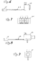
- FIGS. 10 and 11 there is the closure part from two extruded profile strips 58, 59, which are folded by means of a Sheets 60 are interconnected.
- the profile strips 58, 59 exist made of plastic or an aluminum alloy.
- the profile bar 59 is provided with an undercut longitudinal groove 62 in the corresponding profiled heads provided holder 63 are held. At least two such holders 63 hold a rod 48 (or 50).
- the modules 46, 47, 51 or 52 are with holders that can be attached to the rod 48 provided, which are clipped onto the rod 48, for example.
- the modules 46, 47 are fixed by means of permanent magnets 64.
- the stationary closure part is an extruded profile made of plastic or aluminum is made. It also has an undercut groove 65 in which the holder 63 of the rod 48 are inserted. These rods 48 (or also 50) carry the modules 46 or 47. The fixation of the modules 46, 47 takes place in this embodiment by means of a detent spring 66 which in an undercut of the closure part engages. In the undercut Groove 65 can be arranged further holders that another Wear rod 67. The shelves 27 or 28 are supported, which are bent against the legs Support the locking part.
- FIG. 15 shows a modified embodiment of a profile rail 68, which is used as a stationary closure part.
- This profile rail 68 is also an extruded profile that is integral with a bracket 69 is trained.
- This console 69 is used to receive a terminal 39, as shown in Fig. 3, or for receiving a Screen or a printer of a data processing system.
- On a guide groove 70 is provided in the underside of the console, in which Modules of acceptance elements and / or control elements can be moved can be performed.
- FIG. 16 shows a further embodiment of a profile rail 71 which is suitable as a stationary locking part and below the console 69 forms a chamber, on the bottom of which the guide profile 70 is provided is. Closure elements can be placed in the front of this chamber 72 are used, the connection elements or controls take up.
- rods 75, 77 correspond to the rods 48, 50 and 67 also used in the area of the base of the laboratory tables can be used as handle elements.
- rod 75 attached to a drawer 74 that serves as a handle.
- This also offers the advantage of being at this Rod a console 76 hung and on the front of the drawer 74 can be supported, for example to accommodate a keyboard serves a computer unit.
- a similar handle element in shape A rod 77 can then also on a door 78 of the base of the laboratory table be attached.
- connection or removal elements On the user side between connection or removal elements, operating elements, display elements, Storage or storage elements and functional elements different types, such as lights, screen consoles, Keyboard panels, template holders, test tube holders, Paper roll holder or the like.
- These elements are called Modules housed in suitable boxes or housings or the like and with a few standardized fastening techniques on the installation element appropriate.
- the individual electrical modules or sanitary modules as well as controls and display fields can be from the Laboratory technicians are placed where they are needed. The Laboratory technicians can combine and coordinate the modules in such a way that results in an optimum for him, especially with regard to the shortest gripping distances and directly viewable ads.
- the separation into modules forms the basis for series production of similar modules with cables, Cables and connectors.
- the horizontal routing of the installation lines takes place in a systematic way Grid on top of each other in an upper installation room, i.e. in an installation room above the table surface.
- the space below the table top can be used for Waste water discharge or waste water tanks can be used.
- the installation lines can both on installation lines coming from the ceiling connected, so that then an upper feed takes place or a feed from below.
- the openable or removable closure parts on the user side of the media cell those in the manner of sliding doors or as swing or rotary flaps can be designed, allow the inside of the media cell at any time and accessible without tools.
- the media cell is easy to decontaminate, especially also in the area of the transition from the table top 21, 21 'to that of the stationary and openable closure parts User side.
- the wall-like installation element 20 can reach the bottom of the laboratory be closed like a wall. But it can also come from up to the Free-standing side supports exist on the top of the table top. About that it is of course also possible to use the wall-like installation element hanging on the underside of the ceiling of a laboratory room.
- the installation element 20 can also be set up free-standing, so that movable laboratory tables are delivered to him if necessary.
Landscapes
- Health & Medical Sciences (AREA)
- Clinical Laboratory Science (AREA)
- Chemical & Material Sciences (AREA)
- Chemical Kinetics & Catalysis (AREA)
- Devices For Use In Laboratory Experiments (AREA)
- Apparatus Associated With Microorganisms And Enzymes (AREA)
Applications Claiming Priority (2)
| Application Number | Priority Date | Filing Date | Title |
|---|---|---|---|
| DE10154128 | 2001-10-25 | ||
| DE2001154128 DE10154128B4 (de) | 2001-10-25 | 2001-10-25 | Medienzelle für ein Labor oder dergleichen |
Publications (2)
| Publication Number | Publication Date |
|---|---|
| EP1306132A2 true EP1306132A2 (fr) | 2003-05-02 |
| EP1306132A3 EP1306132A3 (fr) | 2004-03-24 |
Family
ID=7704575
Family Applications (1)
| Application Number | Title | Priority Date | Filing Date |
|---|---|---|---|
| EP02021949A Withdrawn EP1306132A3 (fr) | 2001-10-25 | 2002-09-28 | Dispositif de connection de lignes d'alimentation pour laboratoire |
Country Status (2)
| Country | Link |
|---|---|
| EP (1) | EP1306132A3 (fr) |
| DE (1) | DE10154128B4 (fr) |
Cited By (2)
| Publication number | Priority date | Publication date | Assignee | Title |
|---|---|---|---|---|
| WO2010119134A3 (fr) * | 2009-04-17 | 2011-04-21 | Waldner Laboreinrichtungen Gmbh & Co. Kg | Canal d'énergie pour une installation de laboratoire |
| DE102010056066A1 (de) | 2010-12-23 | 2012-06-28 | Köttermann Gmbh & Co. Kg | Verbindungselement zur Erstellung von Medienzellen |
Families Citing this family (5)
| Publication number | Priority date | Publication date | Assignee | Title |
|---|---|---|---|---|
| DE102005047194B3 (de) * | 2005-09-23 | 2007-04-19 | GfP (Gesellschaft für Produktivitätsplanung und Produktentwicklung) mbH | Moduleinheit zur Bildung eines Tischabzugs und deren Verwendung |
| DE202008016891U1 (de) * | 2008-12-19 | 2010-05-12 | VS Vereinigte Spezialmöbelfabriken GmbH & Co. KG | Laborarbeitsplatz |
| DE102009020726A1 (de) * | 2009-05-11 | 2010-11-25 | Wesemann Gmbh & Co. Kg | Versorgungssystem zum Bereitstellen einer Medienversorgung |
| DE102013013389A1 (de) * | 2013-08-13 | 2015-02-19 | Wesemann Gmbh | Medienversorgungseinrichtung und Versorgungssystem mit einer solchen Medienversorgungseinrichtung |
| DE102020113461A1 (de) | 2020-05-19 | 2021-11-25 | seiwo Technik GmbH | Modularer Schutzraum, Bausatz zur Herstellung eines modularen Schutzraumes und Bausatz zur Umrüstung bestehender Räume, sowie Durchreiche für einen Schutzraum |
Citations (1)
| Publication number | Priority date | Publication date | Assignee | Title |
|---|---|---|---|---|
| EP0486789A2 (fr) | 1990-11-21 | 1992-05-27 | ARREDI TECNICI VILLA S.p.A. | Système modulaire pour obtenir des murs équipés et tables de travail, surtout pour utilisation dans des laboratoires |
Family Cites Families (11)
| Publication number | Priority date | Publication date | Assignee | Title |
|---|---|---|---|---|
| FR2411633A1 (fr) * | 1977-12-16 | 1979-07-13 | Alsthom Atlantique | Dispositif de support pour equipement de salles de laboratoire et de fabrication |
| GB2104375B (en) * | 1981-08-14 | 1985-11-06 | Francois Prosper Fernand Drake | Laboratory equipment |
| US4544214A (en) * | 1982-12-15 | 1985-10-01 | Architectural Resources Cambridge, Inc. | Laboratory furniture system |
| DE3739815A1 (de) * | 1986-11-27 | 1988-06-09 | Waldner Electronics Gmbh & Co | Leitungskanalbord |
| DE9316330U1 (de) * | 1993-10-26 | 1994-01-13 | Erfi Ernst Fischer GmbH & Co, 72250 Freudenstadt | Aufbau für Labor- oder Arbeitstische |
| DE4338428C2 (de) * | 1993-11-10 | 1998-05-20 | Wrt Laborbau Gmbh & Co Kg | Laboreinrichtung |
| DE9406097U1 (de) * | 1994-04-13 | 1994-06-09 | Wesemann Gmbh & Co., 28857 Syke | Laboreinrichtungsgegenstand, beispielsweise Labortisch, Laborregal, Steharbeitsplatz o.dgl. |
| DE19619027A1 (de) * | 1996-03-18 | 1997-12-04 | Wilfried Poellet | Stromversorgung |
| DE19614370C1 (de) * | 1996-04-11 | 1997-12-18 | Waldner Laboreinrichtungen | Laborarbeitsplatz |
| DE19618724A1 (de) * | 1996-05-09 | 1997-12-11 | Waldner Laboreinrichtungen | Medienverteiler |
| DE29909492U1 (de) * | 1999-05-31 | 1999-08-12 | Knürr-Mechanik für die Elektronik AG, 81829 München | Arbeitsmöbel |
-
2001
- 2001-10-25 DE DE2001154128 patent/DE10154128B4/de not_active Expired - Fee Related
-
2002
- 2002-09-28 EP EP02021949A patent/EP1306132A3/fr not_active Withdrawn
Patent Citations (1)
| Publication number | Priority date | Publication date | Assignee | Title |
|---|---|---|---|---|
| EP0486789A2 (fr) | 1990-11-21 | 1992-05-27 | ARREDI TECNICI VILLA S.p.A. | Système modulaire pour obtenir des murs équipés et tables de travail, surtout pour utilisation dans des laboratoires |
Cited By (3)
| Publication number | Priority date | Publication date | Assignee | Title |
|---|---|---|---|---|
| WO2010119134A3 (fr) * | 2009-04-17 | 2011-04-21 | Waldner Laboreinrichtungen Gmbh & Co. Kg | Canal d'énergie pour une installation de laboratoire |
| DE102010056066A1 (de) | 2010-12-23 | 2012-06-28 | Köttermann Gmbh & Co. Kg | Verbindungselement zur Erstellung von Medienzellen |
| WO2012089191A1 (fr) | 2010-12-23 | 2012-07-05 | Köttermann Gmbh & Co. Kg | Élément d'assemblage permettant de créer des cellules d'énergie |
Also Published As
| Publication number | Publication date |
|---|---|
| EP1306132A3 (fr) | 2004-03-24 |
| DE10154128B4 (de) | 2009-09-03 |
| DE10154128A1 (de) | 2003-05-15 |
Similar Documents
| Publication | Publication Date | Title |
|---|---|---|
| EP0107162B1 (fr) | Bureau | |
| EP0681439B1 (fr) | Meuble de travail | |
| DE69121522T2 (de) | Modulares System um ausgestattete Mauer und Arbeitstische zu erreichen, besonders für Laboratoriumsanwendung | |
| EP2419979A2 (fr) | Canal d'énergie pour une installation de laboratoire | |
| EP0398014B1 (fr) | Système d'ameublement variable pour atelier | |
| DE10154128B4 (de) | Medienzelle für ein Labor oder dergleichen | |
| EP0800865B1 (fr) | Poste de travail de laboratoire | |
| DE10107912B4 (de) | Einrichtung zum Installieren von Versorgungsleitungen | |
| DE10057556A1 (de) | Stativkopf, insbesondere für eine medizinische Überwachungs- und Versorgungseinrichtung, Trägerprofil für einen solchen und Gerätewagen | |
| AT407945B (de) | Vorrichtung zum aufnehmen eines monitors, einer eingabetastatur und eines diskettenlaufwerkes | |
| EP2241220B1 (fr) | Placard de hauteur d'étage | |
| AT412520B (de) | Einrichtung zum installieren von versorgungsleitungen | |
| AT414142B (de) | Einrichtung zum zu- und/oder abführen von medien und/oder energie zu laborarbeitsplätzen | |
| DE3439626A1 (de) | Arbeits-mobiliar | |
| CH677179A5 (fr) | ||
| DE202007018425U1 (de) | Arbeitsplatzsystem | |
| DE10165022B4 (de) | Einrichtung zum Installieren von Versorgungsleitungen | |
| EP0582945A2 (fr) | Elément de mur multifonctionnel pour équipements de bureau et d'autres équipements de poste de travail | |
| DE10164886B4 (de) | Einrichtung zum Installieren von Versorgungsleitungen | |
| DE60315580T2 (de) | Labormöbel-Konstruktionssystem | |
| WO1995005103A1 (fr) | Appareil de distribution de courant pour meubles de bureau | |
| DE202013102386U1 (de) | Vorrichtung zur Durchführung oder Befestigung von Leitungen und Verteilerschrank | |
| EP1705303B1 (fr) | Système pour aménagement intérieur | |
| DE102010049219A1 (de) | Mediensäule | |
| DE202008016891U1 (de) | Laborarbeitsplatz |
Legal Events
| Date | Code | Title | Description |
|---|---|---|---|
| PUAI | Public reference made under article 153(3) epc to a published international application that has entered the european phase |
Free format text: ORIGINAL CODE: 0009012 |
|
| AK | Designated contracting states |
Designated state(s): AT BE BG CH CY CZ DE DK EE ES FI FR GB GR IE IT LI LU MC NL PT SE SK TR |
|
| AX | Request for extension of the european patent |
Extension state: AL LT LV MK RO SI |
|
| PUAL | Search report despatched |
Free format text: ORIGINAL CODE: 0009013 |
|
| AK | Designated contracting states |
Kind code of ref document: A3 Designated state(s): AT BE BG CH CY CZ DE DK EE ES FI FR GB GR IE IT LI LU MC NL PT SE SK TR |
|
| AX | Request for extension of the european patent |
Extension state: AL LT LV MK RO SI |
|
| 17P | Request for examination filed |
Effective date: 20040724 |
|
| AKX | Designation fees paid |
Designated state(s): AT BE BG CH CY CZ DE DK EE ES FI FR GB GR IE IT LI LU MC NL PT SE SK TR |
|
| STAA | Information on the status of an ep patent application or granted ep patent |
Free format text: STATUS: THE APPLICATION IS DEEMED TO BE WITHDRAWN |
|
| 18D | Application deemed to be withdrawn |
Effective date: 20140401 |