EP1306193B1 - Mit elektrischen Betätigungseinrichtungen versehene Vorrichtung zum Blasformen von Kunststoff-Behältern - Google Patents
Mit elektrischen Betätigungseinrichtungen versehene Vorrichtung zum Blasformen von Kunststoff-Behältern Download PDFInfo
- Publication number
- EP1306193B1 EP1306193B1 EP02079099A EP02079099A EP1306193B1 EP 1306193 B1 EP1306193 B1 EP 1306193B1 EP 02079099 A EP02079099 A EP 02079099A EP 02079099 A EP02079099 A EP 02079099A EP 1306193 B1 EP1306193 B1 EP 1306193B1
- Authority
- EP
- European Patent Office
- Prior art keywords
- machine according
- moulds
- assembly
- actuating
- longitudinal direction
- Prior art date
- Legal status (The legal status is an assumption and is not a legal conclusion. Google has not performed a legal analysis and makes no representation as to the accuracy of the status listed.)
- Expired - Lifetime
Links
- 239000000463 material Substances 0.000 title claims abstract description 10
- 238000000071 blow moulding Methods 0.000 title description 2
- 238000007664 blowing Methods 0.000 claims abstract description 8
- 238000000465 moulding Methods 0.000 claims abstract description 7
- 238000001125 extrusion Methods 0.000 claims abstract description 3
- 230000008878 coupling Effects 0.000 claims description 14
- 238000010168 coupling process Methods 0.000 claims description 14
- 238000005859 coupling reaction Methods 0.000 claims description 14
- 238000006073 displacement reaction Methods 0.000 claims description 7
- 239000003638 chemical reducing agent Substances 0.000 claims description 6
- 230000005540 biological transmission Effects 0.000 claims description 5
- 238000011109 contamination Methods 0.000 description 2
- 238000004519 manufacturing process Methods 0.000 description 2
- 230000001419 dependent effect Effects 0.000 description 1
- 238000007599 discharging Methods 0.000 description 1
- 239000012263 liquid product Substances 0.000 description 1
- 238000004806 packaging method and process Methods 0.000 description 1
- 238000011144 upstream manufacturing Methods 0.000 description 1
Images

Classifications
-
- B—PERFORMING OPERATIONS; TRANSPORTING
- B29—WORKING OF PLASTICS; WORKING OF SUBSTANCES IN A PLASTIC STATE IN GENERAL
- B29C—SHAPING OR JOINING OF PLASTICS; SHAPING OF MATERIAL IN A PLASTIC STATE, NOT OTHERWISE PROVIDED FOR; AFTER-TREATMENT OF THE SHAPED PRODUCTS, e.g. REPAIRING
- B29C49/00—Blow-moulding, i.e. blowing a preform or parison to a desired shape within a mould; Apparatus therefor
- B29C49/42—Component parts, details or accessories; Auxiliary operations
- B29C49/56—Opening, closing or clamping means
- B29C49/5607—Electrically operated, e.g. the closing or opening is done with an electrical motor direct drive
-
- B—PERFORMING OPERATIONS; TRANSPORTING
- B29—WORKING OF PLASTICS; WORKING OF SUBSTANCES IN A PLASTIC STATE IN GENERAL
- B29C—SHAPING OR JOINING OF PLASTICS; SHAPING OF MATERIAL IN A PLASTIC STATE, NOT OTHERWISE PROVIDED FOR; AFTER-TREATMENT OF THE SHAPED PRODUCTS, e.g. REPAIRING
- B29C49/00—Blow-moulding, i.e. blowing a preform or parison to a desired shape within a mould; Apparatus therefor
- B29C49/02—Combined blow-moulding and manufacture of the preform or the parison
- B29C49/04—Extrusion blow-moulding
-
- B—PERFORMING OPERATIONS; TRANSPORTING
- B29—WORKING OF PLASTICS; WORKING OF SUBSTANCES IN A PLASTIC STATE IN GENERAL
- B29C—SHAPING OR JOINING OF PLASTICS; SHAPING OF MATERIAL IN A PLASTIC STATE, NOT OTHERWISE PROVIDED FOR; AFTER-TREATMENT OF THE SHAPED PRODUCTS, e.g. REPAIRING
- B29C49/00—Blow-moulding, i.e. blowing a preform or parison to a desired shape within a mould; Apparatus therefor
- B29C49/28—Blow-moulding apparatus
- B29C49/30—Blow-moulding apparatus having movable moulds or mould parts
- B29C49/32—Blow-moulding apparatus having movable moulds or mould parts moving "to and fro"
-
- B—PERFORMING OPERATIONS; TRANSPORTING
- B29—WORKING OF PLASTICS; WORKING OF SUBSTANCES IN A PLASTIC STATE IN GENERAL
- B29C—SHAPING OR JOINING OF PLASTICS; SHAPING OF MATERIAL IN A PLASTIC STATE, NOT OTHERWISE PROVIDED FOR; AFTER-TREATMENT OF THE SHAPED PRODUCTS, e.g. REPAIRING
- B29C49/00—Blow-moulding, i.e. blowing a preform or parison to a desired shape within a mould; Apparatus therefor
- B29C49/42—Component parts, details or accessories; Auxiliary operations
- B29C49/56—Opening, closing or clamping means
- B29C49/5601—Mechanically operated, i.e. closing or opening of the mould parts is done by mechanic means
- B29C49/5603—Mechanically operated, i.e. closing or opening of the mould parts is done by mechanic means using toggle mechanism
Definitions
- the present invention relates to a machine for blowing plastic containers, with electric means for moving the mould.
- said containers are formed in suitable blow-moulding machines provided with associated moulds (formed by two movable half-moulds) into which a tube of plastic material extruded upstream is introduced.
- the technical problem which is posed, therefore, is that of providing a machine for blowing plastic containers which does not cause contamination of the various parts of the machine and the surrounding environment.
- the machine should ensure the possibility of adjusting in a precise and simple manner the distance of the two half-moulds with respect to a reference axis of symmetry, in order to ensure precision in closing of the mould and a constant closing force thereof, also upon variation in the thickness of the two half-moulds in relation to the container models to be blown.
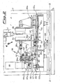
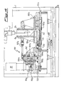
- the machine comprises a support frame 1 which has, constrained thereto, the means 2 for extrusion of the tube 3 of plastic material, the means 100 for moving the mould 4 in the longitudinal direction X-X, the means 200 for moving the mould 4 in the transverse direction Y-Y, the blowing nozzles 5 and the means 6 for removal of the moulded containers 3a.
- Said mould 4 is formed by two half-moulds 4a,4b symmetrically arranged with respect to a fixed reference axis of symmetry Z-Z.
- said means 100 for performing movement in the longitudinal direction comprise an electric motor 101 which is arranged parallel to the axis Z-Z and the shaft 101a of which carries a gear 101b suitable for engagement with a corresponding toothed wheel 102b mounted on a shaped sleeve 102 in turn arranged parallel to the axis Z-Z.
- the sleeve 102 has suitable opposite and externally open seats 102a which receive internally respective spindles 103 having, mounted at their free end, the small end of a respective connecting rod 104a,104b, the big end of which is pivotably mounted on one end of a respective rod 105a,105b.
- the lower rod 105a is connected to the carriage 106b supporting the half-mould 4b and sliding on the said rail 107 by means of the arrangement, in between, of a device 110 for adjusting the distance of the two half-moulds with respect to the fixed axis of symmetry Z-Z.
- Said adjustment device 110 comprises a bracket 111 to which the other free end of the rod 105b is fastened; the bracket 111 is in turn connected to one end of a sleeve 112, the other end of which is constrained to the base of the carriage 106b of the half-mould 4b by means of a screw/internal thread coupling 112a.
- the sleeve 112 has passing through it a splined shaft 113 extending parallel to the longitudinal axis of the machine.
- the rear end of the splined shaft 113 is provided with a screw/internal thread coupling 122a connecting the splined shaft itself and a support 122 in turn joined to a slide 120 movable on longitudinal rails 121, which slide carries all of the part of the actuating assembly 100 formed by the kinematic chain comprising motor 101 and rods 105a,105b.
- the pitch of the front screw/internal thread coupling 122a is double the pitch of the rear screw/internal thread coupling 122a and the two couplings operate in the opposite sense to each other so as to ensure the correct relative displacement of the two carriages 106a,106b, as will appear more clearly below.
- a hexagonal member 113a is provided for actuation of the said shaft by suitable means (not shown).
- Said devices 200 for displacement of the moulding assembly in the transverse direction Y-Y consist of a motor-reducer unit 210, the shaft 210a of which supports the small end of a connecting rod 211, the big end of which is pivotably mounted on the first end of a rod 212, the other end of which is pivotably mounted on the mould-support assembly.
- the rod 212 is interrupted and its continuity is ensured by a sleeved joint 213, the ends of which are coupled to the respective rod portions 212 by means of a screw/internal thread coupling operating in the opposite sense.
- the connecting rods, the rods, the splined shafts and the associated accessories may be duplicated so as to ensure an improved alignment and supporting and actuating capacity using elements which, although greater in number, may nevertheless be made with smaller dimensions which comply with normal production standards.
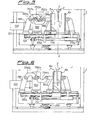
- Figures 5 and 6 show a second embodiment of the machine according to the invention, in which the actuating motor 1101 is arranged with its axis horizontal and operates a reducer 1102, the horizontal shaft of which supports a flat member 1102a to which two pins 1102b arranged at 180° with respect to each other are constrained.
- One end of a connecting rod 1104a, 1104b is pivotably mounted on each pin 1102b, the other end thereof being respectively joined to:
Landscapes
- Engineering & Computer Science (AREA)
- Manufacturing & Machinery (AREA)
- Mechanical Engineering (AREA)
- Blow-Moulding Or Thermoforming Of Plastics Or The Like (AREA)
- Moulds For Moulding Plastics Or The Like (AREA)
- Processing And Handling Of Plastics And Other Materials For Molding In General (AREA)
- Table Devices Or Equipment (AREA)
Claims (15)
- Maschine zum Formen von Behältern (3a), die aus Kunststoffmaterial bestehen, umfassend eine Anordnung (2) zum Extrudieren von Röhren (3) aus Kunststoffmaterial, eine Blasformungsanordnung (5), eine Form zur Aufnahme von Behältern (3a), die aus zwei Halbformen (4a, 4b) gebildet ist, die mit einem entsprechenden Schlitten (6a, 6b) verbunden sind, der bei Betätigung zugehöriger erster Mittel (100) in eine Längsrichtung (X-X) und symmetrisch in Bezug auf eine feststehende Achse (Z-Z) senkrecht zu der Längsrichtung bewegbar ist, wobei die Anordnung, die durch die Form (4) und die zugehörigen ersten Betätigungsmittel (100) gebildet ist, bei Betätigung zweiter Betätigungsmittels (200) in einer Querrichtung (Y-Y) aus einer Position, die der Extrusionsanordnung entspricht, in eine Position, die der Blasformungsanordnung entspricht, und umgekehrt bewegbar ist, wobei die ersten Mittel zur Betätigung der Halbformen (4a, 4b) in die Längsrichtung von der elektrischen Art sind, und Mittel (110) zum symmetrischen Einstellen des Abstandes der zwei Halbformen (4a, 4b) zu der feststehenden Achse (Z-Z) bereitgestellt sind,
dadurch gekennzeichnet, dass
die Schlitten (6a, 6b) entlang einer feststehenden Schiene (107) symmetrisch bewegbar sind,
die ersten Betätigungsmittel (100) auf einem Gleiter (120) montiert sind, der in die Längsrichtung auf zugehörigen feststehenden Schienen (121) bewegbar ist,
die Mittel (110) zum Einstellen des relativen Abstandes der zwei Halbformen (4a, 4b) zwischen dem Gleiter (120) und dem vorderen Schlitten (106b) angeordnet sind,
ein solches Einstellmittel eine Muffe (112) umfasst, die parallel zu der Längsrichtung (X-X) liegt, und von der ein erstes Ende mit der Stange (105b) verbunden ist, die den vorderen Schlitten (106b) betätigt, und von der das andere Ende auf die Basis des Schlittens (106b) mit Hilfe einer Schrauben-/Innengewinde-Anordnung (112a) gespannt ist,
und dadurch, dass
die zweiten Mittel (200) zum Betätigen der Formungsanordnung (4) in die Querrichtung vom elektrischen Typ sind. - Maschine nach Anspruch 1, dadurch gekennzeichnet, dass die ersten Mittel (100) zum Bewegen der zwei Halbformen aus einem Elektromotor (101) bestehen, dessen Welle (101) mit einer Übertragungsanordnung verbunden ist, die an die zugehörigen Schlitten (6a, 6b) angeschlossen ist, die die zwei Halbformen tragen.
- Maschine nach Anspruch 2, dadurch gekennzeichnet, dass die Übertragungsanordnung mindestens zwei Stangen (105a, 105b) umfasst, die jeweils an den Schlitten (106a, 106b) und an entsprechenden Verbindungsstangen (104a, 104b; 1104a, 1104b) angeordnet sind.
- Maschine nach Anspruch 3, dadurch gekennzeichnet, dass die Verbindungsstangen (104a, 104b; 1104a, 1104b) in Längsrichtung (X-X) einander gegenüber liegend angeordnet sind.
- Maschine nach Anspruch 4, dadurch gekennzeichnet, dass die Verbindungsstangen (104a, 104b) eine Drehachse parallel zu der Symmetrieachse (Z-Z) aufweisen und durch ein Zahnrad (103) betätigt werden, an dem sie schwenkbar montiert sind und das durch die Antriebswelle (101a) in Drehung versetzt wird.
- Maschine nach Anspruch 3, dadurch gekennzeichnet, dass die Verbindungsstangen (1104a, 1104b) durch ein flaches Element (1102a) betätigt werden, das mit der Welle eines Getriebes (1102) verbunden ist.
- Maschine nach Anspruch 6, dadurch gekennzeichnet, dass das flache Element (1102a) um eine horizontale Achse dreht.
- Maschine nach Anspruch 6, dadurch gekennzeichnet, dass der Motor (1101), der das Getriebe (1102) betätigt, eine Achse parallel zu der Richtung (X-X) der Verschiebung der zwei Halbmodule (4a, 4b) aufweist.
- Maschine nach Anspruch 1, dadurch gekennzeichnet, dass durch die Muffe (112) eine Keilwelle (113) hindurchgeht, die sich parallel zu der Längsachse der Maschine erstreckt.
- Maschine nach Anspruch 9, dadurch gekennzeichnet, dass eine Schrauben-/Innengewinde-Kopplung (122a) an dem hinteren Ende der Keilwelle (112) bereitgestellt ist, zwischen der Keilwelle und einem Träger (122), der seinerseits mit dem Gleiter verbunden ist.
- Maschine nach Anspruch 10, dadurch gekennzeichnet, dass die Steigung der vorderen Schrauben-/Innengewinde-Kopplung (122a) die doppelte Steigung der hinteren Schrauben-/Innengewinde-Kopplung (122a) ist und die beiden Kopplungen in entgegen gesetzter Richtung zueinander arbeiten.
- Maschine nach Anspruch 11, dadurch gekennzeichnet, dass das vordere Ende der Keilwelle (113) mit einem hexagonalen Element (113a) zur Betätigung der Welle bereitgestellt ist.
- Maschine nach Anspruch 1, dadurch gekennzeichnet, dass das zweite Mittel (200) zum Betätigen der Form (4) in die Querrichtung aus einer Motorgetriebeeinheit (210, 210a) besteht, die an eine Bewegungsübertragungsanordnung angeschlossen ist.
- Maschine nach Anspruch 13, dadurch gekennzeichnet, dass die Übertragungsanordnung eine Verbindungsstange (211) umfasst, deren kleines Ende schwenkbar an der Welle (210a) des Getriebes montiert ist und deren großes Ende schwenkbar an dem ersten Ende einer Stange (212) montiert ist, deren anderes Ende schwenkbar an der Formenträgeranordnung montiert ist.
- Maschine nach Anspruch 14, dadurch gekennzeichnet, dass die Stange (212) unterbrochen ist und ihre Kontinuität mit Hilfe einer Muffenverbindung (213) wiederhergestellt wird, deren Enden an die entsprechenden Stangenabschnitte (212) mit Hilfe einer Schrauben-/Innengewinde-Kopplung gekoppelt sind, die in die entgegen gesetzte Richtung arbeitet.
Applications Claiming Priority (2)
| Application Number | Priority Date | Filing Date | Title |
|---|---|---|---|
| ITMI20012230 | 2001-10-24 | ||
| IT2001MI002230A ITMI20012230A1 (it) | 2001-10-24 | 2001-10-24 | Macchina per la formatura a soffiaggio di contenitori in materiale plastico dotata di dispositivi di azionamento di tipo elettrico |
Publications (3)
| Publication Number | Publication Date |
|---|---|
| EP1306193A2 EP1306193A2 (de) | 2003-05-02 |
| EP1306193A3 EP1306193A3 (de) | 2003-10-15 |
| EP1306193B1 true EP1306193B1 (de) | 2008-12-31 |
Family
ID=11448539
Family Applications (1)
| Application Number | Title | Priority Date | Filing Date |
|---|---|---|---|
| EP02079099A Expired - Lifetime EP1306193B1 (de) | 2001-10-24 | 2002-10-02 | Mit elektrischen Betätigungseinrichtungen versehene Vorrichtung zum Blasformen von Kunststoff-Behältern |
Country Status (12)
| Country | Link |
|---|---|
| US (1) | US6884059B2 (de) |
| EP (1) | EP1306193B1 (de) |
| JP (1) | JP2003159740A (de) |
| AT (1) | ATE419106T1 (de) |
| AU (1) | AU2002301179B2 (de) |
| BR (1) | BR0203872B1 (de) |
| DE (1) | DE60230574D1 (de) |
| DK (1) | DK1306193T3 (de) |
| ES (1) | ES2319391T3 (de) |
| IT (1) | ITMI20012230A1 (de) |
| NZ (1) | NZ521537A (de) |
| PT (1) | PT1306193E (de) |
Cited By (1)
| Publication number | Priority date | Publication date | Assignee | Title |
|---|---|---|---|---|
| EP3717199B1 (de) * | 2017-11-28 | 2023-01-04 | Weiler Engineering, Inc. | Blasformvorrichtung |
Families Citing this family (12)
| Publication number | Priority date | Publication date | Assignee | Title |
|---|---|---|---|---|
| ITMI20040835A1 (it) * | 2004-04-27 | 2004-07-27 | Magic Mp Spa | Macchina per la formatura di contenitori plastici con motore lineare di movimentazione del gruppo porta stampo |
| DE102004026450B4 (de) * | 2004-05-29 | 2007-10-25 | Krauss Maffei Gmbh | Schließeinheit mit Doppelkurbelantrieb |
| ITBO20050401A1 (it) * | 2005-06-14 | 2006-12-15 | Techne Technipack Engineering | Apparato con motore elettrico per l'azionamento in chiusura ed in apertura dei gruppi a stampo ed a controstampo nelle macchine termoformatrici di prodotti in materia plastica e relativo metodo d'impiego |
| ITMI20060253A1 (it) | 2006-02-13 | 2007-08-14 | Magic Mp S R L | Macchina per la formatura di contenitori plastici con mezzi di movimentazione del gruppo porta stampo a cremagliera lineare |
| ITMI20061982A1 (it) | 2006-10-16 | 2008-04-17 | Magic Mp Spa | Macchina per la formatutra di contentori plastici con mezzi di movimentazione del gruppo porta stampo a doppia biella in linea |
| US20080233229A1 (en) * | 2007-03-22 | 2008-09-25 | The Procter & Gamble Company | Apparatus and method for producing containers |
| EP2263854B1 (de) * | 2008-12-19 | 2013-05-01 | Krones AG | Elektrisch betriebene Blasformmaschine und das Verfahren |
| ITMI20131557A1 (it) * | 2013-09-20 | 2015-03-21 | Magic Mp Spa | Macchina per la realizzazione di contenitori in materiale termoplastico |
| WO2016208895A1 (ko) * | 2015-06-26 | 2016-12-29 | 신우코스텍(주) | 용기 제조 장치 |
| ITUA20163867A1 (it) * | 2016-05-27 | 2016-08-27 | Cristian Andreon | Pressa compatta e veloce per processi di stiro-soffiaggio |
| IT201700035363A1 (it) * | 2017-03-30 | 2018-09-30 | Lanfranchi Srl | Dispositivo per la produzione di contenitori in materiale plastico |
| EP4344852A1 (de) * | 2022-09-30 | 2024-04-03 | BEKUM Maschinenfabriken GmbH | Vorrichtung zum herstellen von hohlkörpern |
Family Cites Families (12)
| Publication number | Priority date | Publication date | Assignee | Title |
|---|---|---|---|---|
| DE2030488A1 (de) * | 1969-01-10 | 1972-01-05 | Mehnert J | Vorrichtung zur Herstellung von Hohlkörpern aus thermoplastischem Kunststoff |
| US3883286A (en) * | 1972-03-08 | 1975-05-13 | Ethyl Dev Corp | Blow molding method and apparatus |
| US4421472A (en) * | 1981-08-31 | 1983-12-20 | R & B Machine Tool Company | Clamp for blow molding machine |
| DE4032659A1 (de) * | 1990-10-15 | 1992-04-16 | Kautex Maschinenbau Gmbh | Verfahren und vorrichtung zur herstellung von hohlkoerpern aus thermoplastischen kunststoff |
| JP2561776B2 (ja) * | 1992-06-17 | 1996-12-11 | 株式会社日本製鋼所 | 中空成形機の型締装置 |
| DE4223314A1 (de) * | 1992-07-13 | 1994-01-20 | Gonzalez Augusto E Salvo | Einrichtung zum Schließen und Öffnen von Formen |
| US5478229A (en) * | 1993-01-29 | 1995-12-26 | The Japan Steel Works, Ltd. | Apparatus for forming hollow article |
| JP2988809B2 (ja) * | 1993-07-21 | 1999-12-13 | 株式会社タハラ | 中空成形機の型締装置 |
| WO1998038025A1 (fr) * | 1995-11-08 | 1998-09-03 | Kao Corporation | Dispositif de serrage pour machines de soufflage |
| DE69740164D1 (de) * | 1997-02-25 | 2011-05-19 | Kao Corp | Blasformmaschine |
| JP3914632B2 (ja) * | 1998-04-02 | 2007-05-16 | 株式会社タハラ | 中空成形機 |
| DE19927138C2 (de) * | 1999-06-15 | 2002-02-28 | Fischer W Mueller Blasformtech | Verfahren und Vorrichtung zum Schließen und Öffnen der Formwerkzeuge einer Kunststoffverarbeitungsmaschine |
-
2001
- 2001-10-24 IT IT2001MI002230A patent/ITMI20012230A1/it unknown
-
2002
- 2002-09-23 NZ NZ521537A patent/NZ521537A/en not_active IP Right Cessation
- 2002-09-24 BR BRPI0203872-2A patent/BR0203872B1/pt not_active IP Right Cessation
- 2002-09-24 AU AU2002301179A patent/AU2002301179B2/en not_active Ceased
- 2002-10-02 DE DE60230574T patent/DE60230574D1/de not_active Expired - Lifetime
- 2002-10-02 AT AT02079099T patent/ATE419106T1/de not_active IP Right Cessation
- 2002-10-02 EP EP02079099A patent/EP1306193B1/de not_active Expired - Lifetime
- 2002-10-02 PT PT02079099T patent/PT1306193E/pt unknown
- 2002-10-02 ES ES02079099T patent/ES2319391T3/es not_active Expired - Lifetime
- 2002-10-02 DK DK02079099T patent/DK1306193T3/da active
- 2002-10-02 US US10/262,917 patent/US6884059B2/en not_active Expired - Fee Related
- 2002-10-24 JP JP2002309462A patent/JP2003159740A/ja active Pending
Cited By (1)
| Publication number | Priority date | Publication date | Assignee | Title |
|---|---|---|---|---|
| EP3717199B1 (de) * | 2017-11-28 | 2023-01-04 | Weiler Engineering, Inc. | Blasformvorrichtung |
Also Published As
| Publication number | Publication date |
|---|---|
| JP2003159740A (ja) | 2003-06-03 |
| ATE419106T1 (de) | 2009-01-15 |
| US6884059B2 (en) | 2005-04-26 |
| NZ521537A (en) | 2004-06-25 |
| ITMI20012230A1 (it) | 2003-04-24 |
| PT1306193E (pt) | 2009-02-25 |
| DK1306193T3 (da) | 2009-03-16 |
| US20030077352A1 (en) | 2003-04-24 |
| BR0203872A (pt) | 2003-07-15 |
| ES2319391T3 (es) | 2009-05-07 |
| BR0203872B1 (pt) | 2010-11-16 |
| EP1306193A3 (de) | 2003-10-15 |
| AU2002301179B2 (en) | 2007-10-04 |
| DE60230574D1 (de) | 2009-02-12 |
| EP1306193A2 (de) | 2003-05-02 |
Similar Documents
| Publication | Publication Date | Title |
|---|---|---|
| AU2002301179B2 (en) | Machine For Blow-Moulding Containers Made Of Plastic Material, With Actuating Devices Of The Electric Type | |
| JP4112658B2 (ja) | ブロー成形機 | |
| AU698516B2 (en) | Composite molding device applied for stretch blow molding | |
| EP1626903B1 (de) | Vorrichtung zum blasformen, füllen und verschliessen von kunststoffbehältern | |
| RU2481948C2 (ru) | Устройство для изготовления резервуаров из синтетического материала, формуемых методом выдувания | |
| US5030083A (en) | Apparatus for manufacturing a hollow synthetic resin product | |
| KR900007347B1 (ko) | 합성수지의 중공성형장치 | |
| BRPI0811255B1 (pt) | aparelho para abertura e fechamento de braços de moldes em máquina modeladora de artefatos de vidro | |
| KR20010040743A (ko) | 목부분을 포함하는 중공체 이동 장치 | |
| US5464635A (en) | Blow molding machine | |
| JPS61500657A (ja) | プラスチック管製造装置 | |
| US4648831A (en) | Blow molding apparatus | |
| US7874828B2 (en) | Machine for moulding plastic containers using means for moving the mould-support unit comprising two in-line connecting rods | |
| EP0913244B1 (de) | Blasformmaschine | |
| CN107297884B (zh) | 吹塑模开合装置和吹塑机 | |
| US4569651A (en) | Blow molding apparatus | |
| EP1591226A1 (de) | Apparat zum Herstellen von Plastikbehältern mit linearem Schrittmotor zum Bewegen der Werkzeughalter | |
| AU773060B2 (en) | I.S. machine | |
| EP1818158B1 (de) | Maschine zum Formen von Kunststoffbehältern mit geradlinigen Haltemitteln zum Bewegen der Formträgereinheit | |
| US4673347A (en) | Multiple station, multiple clamp assembly blow molding machines | |
| EP1588824B1 (de) | Vorrichtung zur Einstellung der Dicke eines extrudierten Vorformlings in einer Blasformvorrichtung | |
| RU2096176C1 (ru) | Устройство для изготовления полых изделий из термопластов | |
| CN116766561B (zh) | 塑料容器吹塑成型装置 | |
| KR0115664Y1 (ko) | 블로우 성형기의 금형 개폐장치 | |
| CN115042397B (zh) | 一种注塑模具 |
Legal Events
| Date | Code | Title | Description |
|---|---|---|---|
| PUAI | Public reference made under article 153(3) epc to a published international application that has entered the european phase |
Free format text: ORIGINAL CODE: 0009012 |
|
| AK | Designated contracting states |
Designated state(s): AT BE BG CH CY CZ DE DK EE ES FI FR GB GR IE IT LI LU MC NL PT SE SK TR |
|
| AX | Request for extension of the european patent |
Extension state: AL LT LV MK RO SI |
|
| PUAL | Search report despatched |
Free format text: ORIGINAL CODE: 0009013 |
|
| AK | Designated contracting states |
Kind code of ref document: A3 Designated state(s): AT BE BG CH CY CZ DE DK EE ES FI FR GB GR IE IT LI LU MC NL PT SE SK TR |
|
| AX | Request for extension of the european patent |
Extension state: AL LT LV MK RO SI |
|
| 17P | Request for examination filed |
Effective date: 20040405 |
|
| 17Q | First examination report despatched |
Effective date: 20040430 |
|
| AKX | Designation fees paid |
Designated state(s): AT BE BG CH CY CZ DE DK EE ES FI FR GB GR IE IT LI LU MC NL PT SE SK TR |
|
| 17Q | First examination report despatched |
Effective date: 20040430 |
|
| GRAP | Despatch of communication of intention to grant a patent |
Free format text: ORIGINAL CODE: EPIDOSNIGR1 |
|
| GRAS | Grant fee paid |
Free format text: ORIGINAL CODE: EPIDOSNIGR3 |
|
| GRAA | (expected) grant |
Free format text: ORIGINAL CODE: 0009210 |
|
| AK | Designated contracting states |
Kind code of ref document: B1 Designated state(s): AT BE BG CH CY CZ DE DK EE ES FI FR GB GR IE IT LI LU MC NL PT SE SK TR |
|
| REG | Reference to a national code |
Ref country code: CH Ref legal event code: EP Ref country code: GB Ref legal event code: FG4D |
|
| REG | Reference to a national code |
Ref country code: CH Ref legal event code: NV Representative=s name: DR. LUSUARDI AG |
|
| REF | Corresponds to: |
Ref document number: 60230574 Country of ref document: DE Date of ref document: 20090212 Kind code of ref document: P |
|
| REG | Reference to a national code |
Ref country code: IE Ref legal event code: FG4D |
|
| REG | Reference to a national code |
Ref country code: PT Ref legal event code: SC4A Free format text: AVAILABILITY OF NATIONAL TRANSLATION Effective date: 20090216 |
|
| REG | Reference to a national code |
Ref country code: DK Ref legal event code: T3 |
|
| REG | Reference to a national code |
Ref country code: GR Ref legal event code: EP Ref document number: 20090400787 Country of ref document: GR |
|
| REG | Reference to a national code |
Ref country code: SE Ref legal event code: TRGR |
|
| REG | Reference to a national code |
Ref country code: ES Ref legal event code: FG2A Ref document number: 2319391 Country of ref document: ES Kind code of ref document: T3 |
|
| PG25 | Lapsed in a contracting state [announced via postgrant information from national office to epo] |
Ref country code: BE Free format text: LAPSE BECAUSE OF FAILURE TO SUBMIT A TRANSLATION OF THE DESCRIPTION OR TO PAY THE FEE WITHIN THE PRESCRIBED TIME-LIMIT Effective date: 20081231 Ref country code: EE Free format text: LAPSE BECAUSE OF FAILURE TO SUBMIT A TRANSLATION OF THE DESCRIPTION OR TO PAY THE FEE WITHIN THE PRESCRIBED TIME-LIMIT Effective date: 20081231 |
|
| PG25 | Lapsed in a contracting state [announced via postgrant information from national office to epo] |
Ref country code: AT Free format text: LAPSE BECAUSE OF FAILURE TO SUBMIT A TRANSLATION OF THE DESCRIPTION OR TO PAY THE FEE WITHIN THE PRESCRIBED TIME-LIMIT Effective date: 20081231 Ref country code: CZ Free format text: LAPSE BECAUSE OF FAILURE TO SUBMIT A TRANSLATION OF THE DESCRIPTION OR TO PAY THE FEE WITHIN THE PRESCRIBED TIME-LIMIT Effective date: 20081231 |
|
| PLBE | No opposition filed within time limit |
Free format text: ORIGINAL CODE: 0009261 |
|
| STAA | Information on the status of an ep patent application or granted ep patent |
Free format text: STATUS: NO OPPOSITION FILED WITHIN TIME LIMIT |
|
| 26N | No opposition filed |
Effective date: 20091001 |
|
| PG25 | Lapsed in a contracting state [announced via postgrant information from national office to epo] |
Ref country code: BG Free format text: LAPSE BECAUSE OF FAILURE TO SUBMIT A TRANSLATION OF THE DESCRIPTION OR TO PAY THE FEE WITHIN THE PRESCRIBED TIME-LIMIT Effective date: 20090331 |
|
| PG25 | Lapsed in a contracting state [announced via postgrant information from national office to epo] |
Ref country code: MC Free format text: LAPSE BECAUSE OF NON-PAYMENT OF DUE FEES Effective date: 20091031 |
|
| PG25 | Lapsed in a contracting state [announced via postgrant information from national office to epo] |
Ref country code: IE Free format text: LAPSE BECAUSE OF NON-PAYMENT OF DUE FEES Effective date: 20091002 |
|
| PGFP | Annual fee paid to national office [announced via postgrant information from national office to epo] |
Ref country code: TR Payment date: 20100930 Year of fee payment: 9 |
|
| PGFP | Annual fee paid to national office [announced via postgrant information from national office to epo] |
Ref country code: DK Payment date: 20101015 Year of fee payment: 9 Ref country code: FR Payment date: 20101112 Year of fee payment: 9 Ref country code: NL Payment date: 20101028 Year of fee payment: 9 |
|
| PGFP | Annual fee paid to national office [announced via postgrant information from national office to epo] |
Ref country code: CH Payment date: 20100930 Year of fee payment: 9 Ref country code: DE Payment date: 20101025 Year of fee payment: 9 Ref country code: FI Payment date: 20101022 Year of fee payment: 9 Ref country code: PT Payment date: 20100930 Year of fee payment: 9 Ref country code: SK Payment date: 20101001 Year of fee payment: 9 |
|
| PGFP | Annual fee paid to national office [announced via postgrant information from national office to epo] |
Ref country code: GR Payment date: 20101101 Year of fee payment: 9 Ref country code: GB Payment date: 20101027 Year of fee payment: 9 Ref country code: IT Payment date: 20101028 Year of fee payment: 9 Ref country code: SE Payment date: 20101021 Year of fee payment: 9 |
|
| PG25 | Lapsed in a contracting state [announced via postgrant information from national office to epo] |
Ref country code: LU Free format text: LAPSE BECAUSE OF NON-PAYMENT OF DUE FEES Effective date: 20091002 |
|
| PGFP | Annual fee paid to national office [announced via postgrant information from national office to epo] |
Ref country code: ES Payment date: 20100930 Year of fee payment: 9 |
|
| PG25 | Lapsed in a contracting state [announced via postgrant information from national office to epo] |
Ref country code: CY Free format text: LAPSE BECAUSE OF FAILURE TO SUBMIT A TRANSLATION OF THE DESCRIPTION OR TO PAY THE FEE WITHIN THE PRESCRIBED TIME-LIMIT Effective date: 20081231 |
|
| REG | Reference to a national code |
Ref country code: PT Ref legal event code: MM4A Free format text: LAPSE DUE TO NON-PAYMENT OF FEES Effective date: 20120402 |
|
| REG | Reference to a national code |
Ref country code: NL Ref legal event code: V1 Effective date: 20120501 |
|
| REG | Reference to a national code |
Ref country code: CH Ref legal event code: PL |
|
| REG | Reference to a national code |
Ref country code: GR Ref legal event code: ML Ref document number: 20090400787 Country of ref document: GR Effective date: 20120503 |
|
| GBPC | Gb: european patent ceased through non-payment of renewal fee |
Effective date: 20111002 |
|
| REG | Reference to a national code |
Ref country code: DK Ref legal event code: EBP |
|
| REG | Reference to a national code |
Ref country code: SE Ref legal event code: EUG Ref country code: SK Ref legal event code: MM4A Ref document number: E 5155 Country of ref document: SK Effective date: 20111002 |
|
| REG | Reference to a national code |
Ref country code: FR Ref legal event code: ST Effective date: 20120629 |
|
| PG25 | Lapsed in a contracting state [announced via postgrant information from national office to epo] |
Ref country code: NL Free format text: LAPSE BECAUSE OF NON-PAYMENT OF DUE FEES Effective date: 20120501 Ref country code: LI Free format text: LAPSE BECAUSE OF NON-PAYMENT OF DUE FEES Effective date: 20111031 Ref country code: SK Free format text: LAPSE BECAUSE OF NON-PAYMENT OF DUE FEES Effective date: 20111002 Ref country code: CH Free format text: LAPSE BECAUSE OF NON-PAYMENT OF DUE FEES Effective date: 20111031 Ref country code: DE Free format text: LAPSE BECAUSE OF NON-PAYMENT OF DUE FEES Effective date: 20120501 |
|
| REG | Reference to a national code |
Ref country code: DE Ref legal event code: R119 Ref document number: 60230574 Country of ref document: DE Effective date: 20120501 |
|
| PG25 | Lapsed in a contracting state [announced via postgrant information from national office to epo] |
Ref country code: GR Free format text: LAPSE BECAUSE OF NON-PAYMENT OF DUE FEES Effective date: 20120503 Ref country code: GB Free format text: LAPSE BECAUSE OF NON-PAYMENT OF DUE FEES Effective date: 20111002 Ref country code: FI Free format text: LAPSE BECAUSE OF NON-PAYMENT OF DUE FEES Effective date: 20111002 Ref country code: FR Free format text: LAPSE BECAUSE OF NON-PAYMENT OF DUE FEES Effective date: 20111102 Ref country code: IT Free format text: LAPSE BECAUSE OF NON-PAYMENT OF DUE FEES Effective date: 20111002 Ref country code: PT Free format text: LAPSE BECAUSE OF NON-PAYMENT OF DUE FEES Effective date: 20120402 |
|
| PG25 | Lapsed in a contracting state [announced via postgrant information from national office to epo] |
Ref country code: DK Free format text: LAPSE BECAUSE OF NON-PAYMENT OF DUE FEES Effective date: 20111031 Ref country code: SE Free format text: LAPSE BECAUSE OF NON-PAYMENT OF DUE FEES Effective date: 20111003 |
|
| REG | Reference to a national code |
Ref country code: ES Ref legal event code: FD2A Effective date: 20131023 |
|
| PG25 | Lapsed in a contracting state [announced via postgrant information from national office to epo] |
Ref country code: TR Free format text: LAPSE BECAUSE OF NON-PAYMENT OF DUE FEES Effective date: 20111002 |
|
| PG25 | Lapsed in a contracting state [announced via postgrant information from national office to epo] |
Ref country code: ES Free format text: LAPSE BECAUSE OF NON-PAYMENT OF DUE FEES Effective date: 20111003 |