EP1306201B1 - Presse - Google Patents
Presse Download PDFInfo
- Publication number
- EP1306201B1 EP1306201B1 EP02256826A EP02256826A EP1306201B1 EP 1306201 B1 EP1306201 B1 EP 1306201B1 EP 02256826 A EP02256826 A EP 02256826A EP 02256826 A EP02256826 A EP 02256826A EP 1306201 B1 EP1306201 B1 EP 1306201B1
- Authority
- EP
- European Patent Office
- Prior art keywords
- shaped main
- plates
- ring
- plate
- main plate
- Prior art date
- Legal status (The legal status is an assumption and is not a legal conclusion. Google has not performed a legal analysis and makes no representation as to the accuracy of the status listed.)
- Expired - Lifetime
Links
Images


Classifications
-
- B—PERFORMING OPERATIONS; TRANSPORTING
- B30—PRESSES
- B30B—PRESSES IN GENERAL
- B30B15/00—Details of, or accessories for, presses; Auxiliary measures in connection with pressing
- B30B15/04—Frames; Guides
- B30B15/048—Laminated frame structures
-
- B—PERFORMING OPERATIONS; TRANSPORTING
- B30—PRESSES
- B30B—PRESSES IN GENERAL
- B30B15/00—Details of, or accessories for, presses; Auxiliary measures in connection with pressing
- B30B15/04—Frames; Guides
Definitions
- the present invention relates to a machine press.
- machine press refers to those press machines wherein a press is driven by a mechanical drive mechanism. This includes presses driven by a crank mechanism, knuckle mechanism, or other link mechanism but excludes oil-pressure presses and other hydraulic presses.
- the crankshaft of a machine press is oriented horizontally to harness the power to drive an automated device.
- the horizontal orientation is for reasons of position, rotational direction, and other factors.
- the crankshaft is integrated with a connecting rod so as to form a crank mechanism.
- one drawback is that the connecting rod undulates vertically.
- vertical movement by the connecting rod causes the thrust load to be displaced vertically.
- the frame of the machine press is required to be much stronger longitudinally, usually by increasing the thickness of the press, so as to assure sufficient rigidity.
- a gear driven press which comprises a framework for mounting a drive shaft which has a belt drive to drive gears connected to one or more crankshaft.
- a press frame in which is mounted a hydraulic press.
- JP 11267897 there is disclosed a hydraulic press.
- US 2,860,571 discloses a laminated press in which the frame is comprised of a plurality of one-piece frame members aligned side-by-side in a laminated-like manner. The frame members have identical configurations to provide a press having a variable size. In one embodiment, C-shaped frame members are aligned side by side.
- the individual laminated press units may be linked together to form a larger press.
- the frame members are instead rectangular.
- Bolster plates are secured to the surface of a bed portion.
- Document US 2,860,571 discloses a press in accordance with the preamble of claim 1.
- An aspect of the present invention configures a crank mechanism wherein the crankshaft is oriented longitudinally and integrated with a connecting rod.
- the crankshaft has an axis of rotation which is disposed in the anteroposterior direction.
- the connecting rod undulates in the lateral direction and therefore generate thrust load in the lateral direction, thereby eliminating the need for frame rigidity longitudinally.
- the invention provides a machine press as claimed in Claim 1.
- a simple structure for the frame is provided by changing the orientation of the crank mechanism so as to orient the crankshaft longitudinally. More specifically, a structure is disclosed as having two ring-shaped main plates which are provided in the front and back and are connected by means of connector plates. An upwardly and downwardly movable slide for the machine press is provided in a space demarcated by four column portions of the ring-shaped main plates and a bolster is provided atop a bed of the ring-shaped main plates. A crankshaft oriented longitudinally is provided at the crown portion of the ring-shaped main plates, and the slide is moved upward and downward by a drive mechanism that includes the crankshaft.
- a link mechanism is also provided in the drive mechanism.
- drive mechanisms that, when the crankshaft is oriented longitudinally, integrates various links along the crankshaft. The lateral thrust load that is generated by such drive mechanisms is addressed by the present device.
- the present device also includes welding bed plates on the inside of the bed portion of the ring-shaped main plates.
- the bed plate increases the rigidity of the bed portion and thereby enables high-precision pressing.
- Holes are provided for material insertion and extraction and affixing reinforcing plates to the ring-shaped main plates around the holes. These holes are located in a left portion and a right portion of the connector plates of the ring-shaped main plates. These holes minimize the extensions of the frame.
- a further embodiment provides a stay that laterally connects the column portions of the ring-shaped main plates, thereby minimizing deformation of the frame and enabling the slide to be moved up and down with high precision.
- the above arrangements may further provide a stay that laterally connects the column portions of the ring-shaped main plates.
- a frame 2 for a machine press 1 includes a crown portion 2b, column portions 2c, and a bed portion 2a.
- Frame 2 also includes main plates 2d, multiple connector plates 2g, 2h, 2i, and reinforcement plates 2e.
- frame 2 is fabricated by providing two main plates 2d, a front main plate 20 and a back main plate 22, connecting main plates 2d with connector plates 2g, 2h, 2i, providing reinforcing plates 2e, and affixing a stay 4.
- frame 2 is made of steel, and connector plates 2g, 2h, 2i are welded between front main plate 20 and back main plate 22 and reinforcing plates 2e are welded to an outside of the front main plate 20 and the back main plate 22.
- Stay 4 may be affixed to the main plates 2d by welding. However, in a preferred arrangement stay 4 is affixed by bolts.
- reinforcing plates 2e serve as legs to secure the machine press 1 to a foundation during installation.
- Other arrangements may omit one or more of connector plates 2g, 2h, 2i, reinforcing plates 2e, and stay 4 depending on the load requirements and design of machine press 1.
- each connector plate 2i has a hole 8 for either the placement of feeding equipment or material insertion and extraction. Holes 8 reduce the longitudinal rigidity of the frame, so reinforcing plates 2e are welded to main plates 2d.
- a control panel 9 is affixed to the outside of reinforcing plate 2e that is affixed to front main plate 20.
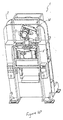
- Figure 4 illustrates an upwardly and downwardly movable slide 5 that is provided in a space demarcated by four column portions 2c.
- Slide 5 is guided by means of guides (not illustrated) provided on column portions 2c and slide 5 moves up and down with high precision.
- Slide 5 is connected to a crankshaft 3 by connecting rods (not illustrated) and moved up and down by a crank mechanism (not illustrated).
- the crankshaft is mounted for rotation about an axis which extends in the anteroposterior direction, i.e. from front to back of the frame 2.
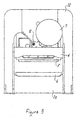
- Figures 1 and 5 illustrate a bolster 6 affixed to bed portion 2a and an upper die (not illustrated) and a lower die (not illustrated) are affixed to a bottom of slide 5 and a top of bolster 6, respectfully. An article is then supplied between slide 5 and bolster 6 is pressed as a result of the movement of slide 5.
- side plates 11 and a bottom plate 12 are provided on the back main plate 22, and a rear plate 10 is provided on the side plates 11 and bottom plate 12.
- Side plates 11, bottom plate 12, rear plate 10 and back main plate 22 form an interior space that contains shafts (not illustrated) and reduction gears (not illustrated) adapted to drive crankshaft 3.
- Side plates 11, bottom plate 12, rear plate 10 and back main plate 22 are affixed by welding.
- flywheel 7 On the outside of the rear plate 10 is a flywheel 7 and a drive motor (not illustrated). Inside flywheel 7 is a clutch brake and although a combined clutch brake is employed in the present arrangement, it is apparent to those of skill in the art that a separate clutch brake may be employed. Additionally, a crank angle indicator (not illustrated) may be included on a front of crankshaft 3.
- Figure 10 illustrates a link drive mechanism 14.
- Link drive mechanism 14 is described in Unexamined Japanese Patent Application publication JP 2002 03 5992 .
- a pair of sliders 5, which support the eccentric portion of the crankshaft 3, are guided along grooves (not illustrated) provided in the arm (not illustrated) so as to allow slide 5 to slide.
- One end of the arm is attached by a pin (not illustrated) to frame 2 of machine press 1 allow the arm to rotate.
- An upper end and lower end of a rod (not illustrated) are respectively connected to the lower end of the arm and to slide 5. The upper and lower ends of the rod are connected to the respective members so as to swivel.
- Figures 4 and 5 illustrate connector plates 2g, 2h, 2i and the other members of the machine press 1 are shown exposed but a preferred arrangement they would be covered to prevent entry of dust and debris.
- Main plates 2d are ring-shaped, a single plate with a hole in the center thereof.
- the shape of main plates 2d are designed to naturally bear the press load.
- a single plate is welded to the inside of main plates 2d to further increase the rigidity of bed portion 2a.
- a bed plate 13 is welded to the inside of main plate 2d and bolster 6 is affixed atop the bed plate 13
- ring-shaped main plates 2d are now an inverted U-shaped plate 102d, and a bed 102a is welded to the inside of a front inverted U-shaped plate 102e and a back inverted U-shaped plate 102f.
- bed 102a is located between inverted U-shaped plates 102d.
- bed 102a is welded to inverted U-shaped plates 102d.
- the thickness of the plates for bed 102a may be selected without being restricted by the thickness of inverted U-shaped plates 102d.
- Bolster 6 is secured atop bed 102a and the longitudinal span defined by bolster 6, located inside inverted U-shaped plates 102d, may be made shorter than the span in the first or second arrangements.
- inverted U-shaped plates 102d are the same as ring-shaped main plates 2d. Therefore, inverted U-shaped plates 102d have a crown 102b and columns 102c similar to those of the ring-shaped main plates 2d.
- the present device is capable of providing a simple machine press capable of withstanding the thrust load of the drive mechanism and the eccentric load of the press.
- the device according to this arrangement has a narrow longitudinal span in the bed and is capable of minimizing deformation of the bolster.
Landscapes
- Engineering & Computer Science (AREA)
- Mechanical Engineering (AREA)
- Presses And Accessory Devices Thereof (AREA)
- Press Drives And Press Lines (AREA)
Claims (6)
- Presse (1) comprenant :un bâti (2) comprenant :une plaque principale avant de forme annulaire (2d, 20),une plaque principale arrière de forme annulaire (2d, 22),etdans laquelle les plaques principales avant et arrière de forme annulaire comprennent des parties de colonnes (2c) qui définissent une ouverture du bâti, les plaques principales avant et arrière de forme annulaire présentant une partie de chapiteau (2b) et une partie de banc (2a), les plaques principales avant et arrière de forme annulaire étant formées sous forme de plaques uniques,un coulisseau (5) disposé dans l'ouverture du bâti entre les parties de colonnes,une plaque d'appui (6) disposée au-dessus de la partie de banc, etun mécanisme d'entraînement (14) comprenant un vilebrequin (3) destiné à entraîner le coulisseau dans des directions vers le haut et vers le bas, le vilebrequin étant disposé à proximité de la partie de chapiteau et étant orienté perpendiculairement à un axe transversal de l'ouverture du bâti qui s'étend à travers les parties de colonnes, caractérisée en ce qu'une pluralité de plaques de raccordement (2g, 2h, 2i) est disposée entre la plaque principale avant de forme annulaire et la plaque principale arrière de forme annulaire pour relier la plaque principale avant de forme annulaire à la plaque principale arrière de forme annulaire et en ce que la partie de banc comprend un socle (13) qui est disposé pour venir en butée contre une surface intérieure de la partie de banc, où chaque plaque de raccordement comporte une ouverture (8) formée à travers celle-ci qui communique avec l'ouverture du bâti pour permettre une insertion et une extraction de matériaux et où des plaques de renfort (2e) sont fixées aux plaques principales avant et arrière de forme annulaire autour de l'ouverture formée dans la plaque de raccordement.
- Presse selon la revendication 1, comprenant en outre : une entretoise (4) reliant latéralement les parties de colonnes.
- Presse selon l'une quelconque des revendications précédentes, dans laquelle le mécanisme d'entraînement comprend un mécanisme de liaison.
- Presse selon l'une quelconque des revendications précédentes, dans laquelle la plaque principale avant de forme angulaire, la plaque principale arrière de forme annulaire et les plaques de raccordement sont soudées ensemble afin de former une structure solidaire.
- Presse selon l'une quelconque des revendications précédentes, dans laquelle la plaque principale avant de forme annulaire, la plaque principale arrière de forme annulaire et les plaques de raccordement sont boulonnées ensemble.
- Presse selon la revendication 1, dans laquelle le socle est soudé à la surface intérieure de la partie de banc.
Priority Applications (1)
| Application Number | Priority Date | Filing Date | Title |
|---|---|---|---|
| EP07023736A EP1894709B1 (fr) | 2001-10-24 | 2002-10-01 | Presse de machines |
Applications Claiming Priority (2)
| Application Number | Priority Date | Filing Date | Title |
|---|---|---|---|
| JP2001325942A JP3897562B2 (ja) | 2001-10-24 | 2001-10-24 | 機械プレス |
| JP2001325942 | 2001-10-24 |
Related Child Applications (2)
| Application Number | Title | Priority Date | Filing Date |
|---|---|---|---|
| EP07023736A Division EP1894709B1 (fr) | 2001-10-24 | 2002-10-01 | Presse de machines |
| EP07023736.7 Division-Into | 2007-12-07 |
Publications (3)
| Publication Number | Publication Date |
|---|---|
| EP1306201A2 EP1306201A2 (fr) | 2003-05-02 |
| EP1306201A3 EP1306201A3 (fr) | 2003-11-12 |
| EP1306201B1 true EP1306201B1 (fr) | 2011-06-22 |
Family
ID=19142407
Family Applications (2)
| Application Number | Title | Priority Date | Filing Date |
|---|---|---|---|
| EP02256826A Expired - Lifetime EP1306201B1 (fr) | 2001-10-24 | 2002-10-01 | Presse |
| EP07023736A Expired - Lifetime EP1894709B1 (fr) | 2001-10-24 | 2002-10-01 | Presse de machines |
Family Applications After (1)
| Application Number | Title | Priority Date | Filing Date |
|---|---|---|---|
| EP07023736A Expired - Lifetime EP1894709B1 (fr) | 2001-10-24 | 2002-10-01 | Presse de machines |
Country Status (3)
| Country | Link |
|---|---|
| US (1) | US6871587B2 (fr) |
| EP (2) | EP1306201B1 (fr) |
| JP (1) | JP3897562B2 (fr) |
Families Citing this family (24)
| Publication number | Priority date | Publication date | Assignee | Title |
|---|---|---|---|---|
| DE202007015149U1 (de) * | 2007-10-30 | 2008-03-27 | Bögle, Michael | Stanzautomat |
| ITBO20100448A1 (it) * | 2010-07-14 | 2012-01-15 | Form Impianti S P A | Telaio per macchine per la produzione di manufatti di calcestruzzo vibrato |
| USD715340S1 (en) * | 2012-10-03 | 2014-10-14 | Zapadoceska Univerzita V Plzni | Press side plate |
| CN105466764B (zh) * | 2016-01-11 | 2019-01-18 | 北京汽车研究总院有限公司 | 一种反力支架结构 |
| USD826999S1 (en) * | 2017-03-07 | 2018-08-28 | Citta International LLC | Manual heat press machine |
| USD826297S1 (en) * | 2017-03-07 | 2018-08-21 | Citta International LLC | Manual heat press machine |
| USD873313S1 (en) * | 2017-03-23 | 2020-01-21 | Stahls' Inc. | Heat press |
| CN107297537B (zh) * | 2017-06-21 | 2018-11-27 | 中钢集团西安重机有限公司 | 一种加强型冷剪机机架 |
| CN107855391A (zh) * | 2017-10-16 | 2018-03-30 | 佛山海格利德机器人智能设备有限公司 | 一种全自动智能板材冲压装置 |
| USD854061S1 (en) * | 2017-11-29 | 2019-07-16 | Jerry Huang | Heat press temperature controller |
| USD867410S1 (en) * | 2017-11-30 | 2019-11-19 | Amerta LLC | Heat press machine |
| USD832897S1 (en) * | 2017-12-05 | 2018-11-06 | Jerry Huang | Press frame with integrated hydraulic ram and return springs |
| USD828412S1 (en) * | 2017-12-05 | 2018-09-11 | Jerry Huang | Press frame with integrated hydraulic ram and return springs |
| USD857065S1 (en) * | 2018-05-17 | 2019-08-20 | Anthony Rebholz | Rosin press |
| USD875149S1 (en) * | 2018-06-22 | 2020-02-11 | Stahls' Inc. | Heat press with flat design |
| USD875148S1 (en) * | 2018-06-22 | 2020-02-11 | Stahls' Inc. | Heat press with cap design |
| USD858591S1 (en) * | 2018-06-22 | 2019-09-03 | Biocut, Llc | Press housing |
| USD894245S1 (en) | 2018-08-06 | 2020-08-25 | Amerta LLC | Heat press machine |
| DE102019001285A1 (de) * | 2019-02-23 | 2020-08-27 | AlDA EUROPE GmbH | System eines Gestells für Pressen und Pressengestell |
| USD935501S1 (en) | 2019-05-13 | 2021-11-09 | Amerta, Llc | Heat press |
| CN110802140B (zh) * | 2019-10-14 | 2025-04-29 | 青岛海德马克智能装备有限公司 | 一种洗衣机外箱料片折弯装置 |
| CN111360508B (zh) * | 2020-03-13 | 2022-04-26 | 诸暨市超前泵业科技有限公司 | 一种水泵铜齿轮砸击装置 |
| USD935493S1 (en) * | 2020-11-04 | 2021-11-09 | Zhi-Gang Cheng | Heat transfer machine |
| USD952009S1 (en) * | 2021-06-30 | 2022-05-17 | Hunan Sijiu Technology Co., Ltd. | Heat press |
Family Cites Families (23)
| Publication number | Priority date | Publication date | Assignee | Title |
|---|---|---|---|---|
| US3523444A (en) * | 1968-01-05 | 1970-08-11 | Cameron Iron Works Inc | Hydraulic press |
| US3858432A (en) * | 1972-09-05 | 1975-01-07 | Minster Machine Co | Press structure |
| US4095522A (en) * | 1977-07-01 | 1978-06-20 | Verson Allsteel Press Company | Sound abatement device for mechanical presses |
| US4169412A (en) * | 1978-09-25 | 1979-10-02 | Owatonna Tool Company | Shop press |
| JPS5584299A (en) * | 1978-12-18 | 1980-06-25 | Aida Eng Ltd | Special knuckle press |
| US4397232A (en) * | 1981-09-08 | 1983-08-09 | The Minster Machine Company | Mechanical press having a drop in drive assembly |
| DE3149243A1 (de) | 1981-12-11 | 1983-06-16 | Maschinenfabrik J. Dieffenbacher Gmbh & Co, 7519 Eppingen | "heizplattenpresse in fensterrahmenkonstruktion" |
| US4615208A (en) * | 1984-03-02 | 1986-10-07 | Hailey Robert W | Hydraulic press frame |
| DD237953A3 (de) * | 1984-12-27 | 1986-08-06 | Warnke Umformtech Veb K | Pressenkoerper geschlossener bauform in schweisskonstruktion fuer zweistaenderpressen |
| IT1196506B (it) | 1986-07-16 | 1988-11-16 | Nassetti Ettore Spa | Incastellatura perfezionata per presa,in particolare per lo stampaggio di materiali ceramici |
| EP0262593B1 (fr) * | 1986-09-29 | 1992-01-08 | Aida Engineering Ltd. | Bâti pour une presse |
| US4947673A (en) * | 1989-04-13 | 1990-08-14 | Connell Limited Partnership | Removable slide presses |
| CH679471A5 (fr) * | 1989-05-03 | 1992-02-28 | Bruderer Ag | |
| US5027638A (en) * | 1990-06-22 | 1991-07-02 | Friestad Roland W | Force-resisting structure |
| JPH08174295A (ja) | 1994-12-27 | 1996-07-09 | Komatsu Ltd | プレス機械 |
| DE59500682D1 (de) * | 1995-01-21 | 1997-10-23 | Bruderer Ag | Stanzpresse mit langem Werkzeugeinbauraum |
| DE19506519A1 (de) | 1995-02-24 | 1996-08-29 | Schuler Pressen Gmbh & Co | Exzenterpresse, insbesondere zum mehrstufigen Kaltfließpressen |
| JPH0929499A (ja) * | 1995-07-25 | 1997-02-04 | Aida Eng Ltd | 機械プレス |
| JP3301484B2 (ja) * | 1996-07-26 | 2002-07-15 | 日立金属株式会社 | 非可逆回路素子 |
| EP0927630B1 (fr) * | 1997-12-12 | 1999-09-08 | Bruderer Ag | Presse, en particulier presse à estamper |
| DE19809746A1 (de) * | 1998-03-06 | 1999-09-16 | Benteler Werke Ag | Vorrichtung zur hydraulischen Umformung von metallischen Hohlkörpern |
| JPH11267897A (ja) * | 1998-03-23 | 1999-10-05 | Senyo Kk | 油圧プレス |
| US6012322A (en) * | 1998-03-27 | 2000-01-11 | Aida Engineering Co., Ltd. | Slide-driving device for knuckle presses |
-
2001
- 2001-10-24 JP JP2001325942A patent/JP3897562B2/ja not_active Expired - Lifetime
-
2002
- 2002-09-25 US US10/256,293 patent/US6871587B2/en not_active Expired - Lifetime
- 2002-10-01 EP EP02256826A patent/EP1306201B1/fr not_active Expired - Lifetime
- 2002-10-01 EP EP07023736A patent/EP1894709B1/fr not_active Expired - Lifetime
Also Published As
| Publication number | Publication date |
|---|---|
| EP1306201A3 (fr) | 2003-11-12 |
| US6871587B2 (en) | 2005-03-29 |
| EP1894709B1 (fr) | 2011-07-06 |
| EP1894709A2 (fr) | 2008-03-05 |
| EP1894709A3 (fr) | 2008-03-12 |
| JP3897562B2 (ja) | 2007-03-28 |
| EP1306201A2 (fr) | 2003-05-02 |
| JP2003126997A (ja) | 2003-05-08 |
| US20030074948A1 (en) | 2003-04-24 |
Similar Documents
| Publication | Publication Date | Title |
|---|---|---|
| EP1306201B1 (fr) | Presse | |
| EP0387884B1 (fr) | Machine d'estampage et de formage pourvue de genouillères pour le mouvement alternatif des outils | |
| JP5526024B2 (ja) | 打抜きプレス機関連する出願の指摘本件出願は、2007年6月28日付で提出された欧州特許出願第07012661の優先権を主張するものであり、したがってその開示内容全体を援用する。 | |
| US7114365B2 (en) | Ram guidance system | |
| US20010002566A1 (en) | Punch press, specifically a high-speed punch press | |
| EP4323129B1 (fr) | Machine à plier permettant de plier des pièces, en particulier presse plieuse | |
| HK1114817A (en) | Machines press | |
| US5873279A (en) | Transfer press | |
| JP2739291B2 (ja) | プレスユニット及び該プレスユニットを用いたトランスファープレス | |
| CN211990770U (zh) | 一种工件锻压用模具 | |
| EP0732161B1 (fr) | Dispositif pour travailler par presse | |
| JP2540450B2 (ja) | C形フレ―ム構造のプレス装置 | |
| CN1138883C (zh) | 横机 | |
| JP7519164B2 (ja) | クラウン構造体及びそれを備えるプレス機械 | |
| CN102216064B (zh) | 压力机械 | |
| US5060566A (en) | Press apparatus | |
| JP7132879B2 (ja) | 金型プレス装置及び金型プレス方法 | |
| JPH11267897A (ja) | 油圧プレス | |
| CN220216419U (zh) | 一种具有连续进料功能的冲孔模具 | |
| JP2001079695A (ja) | プレス機械 | |
| JPS637384Y2 (fr) | ||
| JP2004209491A (ja) | 機械プレスのフレーム | |
| JP2021112768A (ja) | プレスライン | |
| JPH04123900A (ja) | プレス機械のスライドガイド | |
| JP2502331B2 (ja) | タレットパンチプレス機 |
Legal Events
| Date | Code | Title | Description |
|---|---|---|---|
| PUAI | Public reference made under article 153(3) epc to a published international application that has entered the european phase |
Free format text: ORIGINAL CODE: 0009012 |
|
| AK | Designated contracting states |
Designated state(s): AT BE BG CH CY CZ DE DK EE ES FI FR GB GR IE IT LI LU MC NL PT SE SK TR |
|
| AX | Request for extension of the european patent |
Extension state: AL LT LV MK RO SI |
|
| PUAL | Search report despatched |
Free format text: ORIGINAL CODE: 0009013 |
|
| AK | Designated contracting states |
Kind code of ref document: A3 Designated state(s): AT BE BG CH CY CZ DE DK EE ES FI FR GB GR IE IT LI LU MC NL PT SE SK TR |
|
| AX | Request for extension of the european patent |
Extension state: AL LT LV MK RO SI |
|
| RIC1 | Information provided on ipc code assigned before grant |
Ipc: 7B 30B 15/04 A Ipc: 7B 30B 1/26 B |
|
| 17P | Request for examination filed |
Effective date: 20040407 |
|
| AKX | Designation fees paid |
Designated state(s): DE FR GB IT |
|
| RIN1 | Information on inventor provided before grant (corrected) |
Inventor name: KANAMARU, HISANOBUAIDA ENGINEERING Inventor name: ITO,TAKAOAIDA ENGINEERING Inventor name: FUJIMORI, HIROMICHIAIDA ENGINEERING |
|
| 17Q | First examination report despatched |
Effective date: 20040909 |
|
| 17Q | First examination report despatched |
Effective date: 20040909 |
|
| GRAP | Despatch of communication of intention to grant a patent |
Free format text: ORIGINAL CODE: EPIDOSNIGR1 |
|
| GRAC | Information related to communication of intention to grant a patent modified |
Free format text: ORIGINAL CODE: EPIDOSCIGR1 |
|
| GRAS | Grant fee paid |
Free format text: ORIGINAL CODE: EPIDOSNIGR3 |
|
| GRAA | (expected) grant |
Free format text: ORIGINAL CODE: 0009210 |
|
| AK | Designated contracting states |
Kind code of ref document: B1 Designated state(s): DE FR GB IT |
|
| REG | Reference to a national code |
Ref country code: GB Ref legal event code: FG4D |
|
| REG | Reference to a national code |
Ref country code: DE Ref legal event code: R096 Ref document number: 60240329 Country of ref document: DE Effective date: 20110804 |
|
| PLBE | No opposition filed within time limit |
Free format text: ORIGINAL CODE: 0009261 |
|
| STAA | Information on the status of an ep patent application or granted ep patent |
Free format text: STATUS: NO OPPOSITION FILED WITHIN TIME LIMIT |
|
| 26N | No opposition filed |
Effective date: 20120323 |
|
| REG | Reference to a national code |
Ref country code: DE Ref legal event code: R097 Ref document number: 60240329 Country of ref document: DE Effective date: 20120323 |
|
| REG | Reference to a national code |
Ref country code: FR Ref legal event code: PLFP Year of fee payment: 15 |
|
| REG | Reference to a national code |
Ref country code: FR Ref legal event code: PLFP Year of fee payment: 16 |
|
| REG | Reference to a national code |
Ref country code: FR Ref legal event code: PLFP Year of fee payment: 17 |
|
| PGFP | Annual fee paid to national office [announced via postgrant information from national office to epo] |
Ref country code: IT Payment date: 20210910 Year of fee payment: 20 Ref country code: FR Payment date: 20210913 Year of fee payment: 20 |
|
| PGFP | Annual fee paid to national office [announced via postgrant information from national office to epo] |
Ref country code: GB Payment date: 20210901 Year of fee payment: 20 |
|
| PGFP | Annual fee paid to national office [announced via postgrant information from national office to epo] |
Ref country code: DE Payment date: 20210831 Year of fee payment: 20 |
|
| REG | Reference to a national code |
Ref country code: DE Ref legal event code: R071 Ref document number: 60240329 Country of ref document: DE |
|
| REG | Reference to a national code |
Ref country code: GB Ref legal event code: PE20 Expiry date: 20220930 |
|
| PG25 | Lapsed in a contracting state [announced via postgrant information from national office to epo] |
Ref country code: GB Free format text: LAPSE BECAUSE OF EXPIRATION OF PROTECTION Effective date: 20220930 |