EP1306222A2 - Druckgerät und Verfahren zur Steuerung desselben - Google Patents
Druckgerät und Verfahren zur Steuerung desselben Download PDFInfo
- Publication number
- EP1306222A2 EP1306222A2 EP02023750A EP02023750A EP1306222A2 EP 1306222 A2 EP1306222 A2 EP 1306222A2 EP 02023750 A EP02023750 A EP 02023750A EP 02023750 A EP02023750 A EP 02023750A EP 1306222 A2 EP1306222 A2 EP 1306222A2
- Authority
- EP
- European Patent Office
- Prior art keywords
- printing
- time
- motor
- thermal head
- time point
- Prior art date
- Legal status (The legal status is an assumption and is not a legal conclusion. Google has not performed a legal analysis and makes no representation as to the accuracy of the status listed.)
- Granted
Links
- 238000000034 method Methods 0.000 title claims description 15
- 238000010438 heat treatment Methods 0.000 claims abstract description 19
- 238000007599 discharging Methods 0.000 claims 1
- 230000007246 mechanism Effects 0.000 description 6
- 238000004804 winding Methods 0.000 description 5
- 230000005540 biological transmission Effects 0.000 description 2
- 239000000758 substrate Substances 0.000 description 2
- 230000001419 dependent effect Effects 0.000 description 1
- 238000010586 diagram Methods 0.000 description 1
- 239000000463 material Substances 0.000 description 1
Images


Classifications
-
- B—PERFORMING OPERATIONS; TRANSPORTING
- B41—PRINTING; LINING MACHINES; TYPEWRITERS; STAMPS
- B41J—TYPEWRITERS; SELECTIVE PRINTING MECHANISMS, i.e. MECHANISMS PRINTING OTHERWISE THAN FROM A FORME; CORRECTION OF TYPOGRAPHICAL ERRORS
- B41J2/00—Typewriters or selective printing mechanisms characterised by the printing or marking process for which they are designed
- B41J2/315—Typewriters or selective printing mechanisms characterised by the printing or marking process for which they are designed characterised by selective application of heat to a heat sensitive printing or impression-transfer material
- B41J2/32—Typewriters or selective printing mechanisms characterised by the printing or marking process for which they are designed characterised by selective application of heat to a heat sensitive printing or impression-transfer material using thermal heads
- B41J2/35—Typewriters or selective printing mechanisms characterised by the printing or marking process for which they are designed characterised by selective application of heat to a heat sensitive printing or impression-transfer material using thermal heads providing current or voltage to the thermal head
- B41J2/355—Control circuits for heating-element selection
-
- B—PERFORMING OPERATIONS; TRANSPORTING
- B41—PRINTING; LINING MACHINES; TYPEWRITERS; STAMPS
- B41J—TYPEWRITERS; SELECTIVE PRINTING MECHANISMS, i.e. MECHANISMS PRINTING OTHERWISE THAN FROM A FORME; CORRECTION OF TYPOGRAPHICAL ERRORS
- B41J15/00—Devices or arrangements of selective printing mechanisms, e.g. ink-jet printers or thermal printers, specially adapted for supporting or handling copy material in continuous form, e.g. webs
- B41J15/18—Multiple web-feeding apparatus
- B41J15/22—Multiple web-feeding apparatus for feeding webs in separate paths during printing
Definitions
- the present invention relates to a printing apparatus that is designed to print on a plurality of printing media at the same time, and a method of controlling such a printing apparatus.
- a POS station typically includes a personal computer, a display device, a drawer, a printing apparatus and a reader such as a barcode reader.
- the printing apparatus of such a POS station has a receipt printing function for printing a receipt to be handed to a customer (purchaser), and a journal printing function for printing a journal, which is a store transaction copy (disclosed in JP-A-9-234930A and JP-A-9-254496).
- a printing apparatus of this type has two thermal heads, one for printing data on a first printing medium for the receipts and another one for printing on a second printing medium as the journal.
- a printing apparatus of this type when the two thermal heads are operated at the same time, the peak current is high causing a correspondingly high consumption of power.
- the printing of a journal can be started once the printing of a receipt has been completed. In this case, however, an extended time is required to complete the printing of the receipt and the journal, and the desire of a rapid printing process cannot be met.
- two thermal heads do not print concurrently but quasi-concurrently, i.e., in a time-sharing manner. Since the first and second motors are simultaneously driven at the same or nearly the same speed and the first and second thermal heads are energized in a non-overlapping interleaved manner, an increase in the peak current due to a printing on more than one printing medium can be avoided and the peak current can be reduced compared to the case where the active times of the two thermal heads overlap.
- active time of a thermal head is used herein to denote the time period during which the thermal head is energized and consumes power as opposed to the "inactive time" during which the thermal head is not energized.
- printing processes for which both the first and the second thermal head are used can be performed at virtually the same time, a rapid printing operation can be implemented.
- a printing apparatus 100 is adapted to print information on a receipt printing medium and a journal printing medium.
- roll type printing media are used in the embodiments explained below although the invention is applicable to sheet type printing media as well.
- the particular material of the printing media is not important as long as it allows printing by means of a thermal print head.
- the printing medium used for receipt printing will be referred to "receipt paper” and the printing medium used for journal printing will be referred to "journal paper” hereinafter.
- the printing apparatus 100 comprises an elongated case 102, in one longitudinal end face of which (the front face in Fig. 1) a discharge port 104 is formed from which a printed receipt is discharged.
- the side on which the discharge port 104 of the printing apparatus 100 is located is defined as the "front", while the opposite side is defined as the "rear”.
- the case 102 is formed of a lower case portion 106, which accommodates the individual mechanisms of the printing apparatus 100, and an upper case portion 108, which is provided atop the lower case portion 106.
- a front cover 116 is provided that can be opened and closed, while at the top rear of the upper case portion 108 an upper cover 118 is provided that can be opened and closed.
- an operation panel 114 On the front of the upper case portion 108, positioned adjacent to the front cover 116, is an operation panel 114 whereupon switches, such as a power switch, are located.
- switches such as a power switch
- a roll of receipt paper 110 and a roll of journal paper 112 are loaded into the printing apparatus 100.
- the receipt paper and the journal paper used in this embodiment are so-called thermal sensitive printing media that are printed by the application of heat.
- front and rear portions are defined inside of the case 102 of the printing apparatus 100.
- the front section near the discharge port 104, is used for the printing of receipts, and in this section, beginning at the front, an auto cutter 120 for cutting a printed receipt, a receipt printing mechanism 122 for printing a receipt, and a chamber 124 for storing the receipt paper roll 110 are arranged in the named order.
- the rear section is used for journal printing, and in this section, beginning at the front, a journal printing mechanism 126 for printing a journal, a chamber 128 for storing the journal paper roll 112, and a journal winder 130 for winding up the printed journal paper to a roll and for holding the roll are arranged in the named order.
- the receipt printing mechanism 122 includes a thermal head 132 wherein multiple heating elements are aligned in a line on a substrate; a platen roller 134 that is positioned parallel to the thermal head 132; and a motor 136 for rotating the platen roller 134 at a predetermined speed.
- the receipt paper is pulled from the receipt paper roll 110 and is fed to and sandwiched between the thermal head 132 and the platen roller 134.
- the motor 136 such as a four-phase stepping motor, produces a driving force that rotates the platen roller 134 via a transmission (not shown). As the platen roller 134 is rotated, the receipt paper is conveyed in the direction perpendicular to the direction in which the heating elements of the thermal head 132 are arranged.
- the receipt paper When the receipt paper is conveyed at a predetermined speed by the rotation of the motor 136 and the heating elements of the thermal head 132 are selectively energized to generate heat, desired characters or pictures are printed on the receipt paper.
- the printed portion of the receipt paper is then discharged through the discharge port 104 and is cut off the remaining receipt paper by the auto cutter 120 to be output as a receipt.
- the auto cutter 120 is located inside the printing apparatus 100 adjacent to the discharge port 104.
- the platen roller 134 is attached to the front cover 116, and the thermal head 132 is attached to a fixed portion of the upper case portion 108.
- the front cover 116 (Fig. 1) is opened, the thermal head 132 and the platen roller 134 are separated from each other, and since the chamber 124 is exposed and is accessible from the front, the receipt paper roll 110 can be exchanged.
- the journal printing mechanism 126 like the receipt printing mechanism 122, includes a thermal head 142 wherein multiple heating elements are aligned in a line on a support substrate; a platen roller 144 that is positioned opposite to the thermal head 142; and a motor 146 for rotating the platen roller 144 at a predetermined speed.
- the journal paper is pulled from the journal paper roll 112 and is fed to and sandwiched between the thermal head 142 and the platen roller 144.
- the motor 146 such as a four-phase stepping motor, produces a driving force that rotates the platen roller 144 via a transmission (not shown).
- journal paper When the receipt paper is conveyed at a predetermined speed by the rotation of the motor 146 and the heating elements of the thermal head 142 are selectively energized to generate heat, desired characters or pictures are printed on the journal paper.
- the printed journal paper is then conveyed to the journal winder 130, passing over a guide plate 148 that is located above the thermal head 142.
- a winding reel 150 is arranged in the journal winder 130, and when the winding reel 150 is rotated by a motor (not shown), the printed journal is wound around it.
- the upper cover 118 (see Fig. 1) of the upper case portion 108 is opened, the thermal head 142, the design of which provides for this, is separated from the platen roller 144 and the journal paper roll 112 can be exchanged and the roll of printed journal paper can be taken out.
- a controller 200 for controlling printing apparatus 100 comprises a CPU in this embodiment.
- the controller 200 drives the thermal heads 132 and 142 and the motors 136 and 146 to print corresponding characters or pictures on the receipt paper and the journal paper.
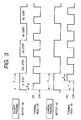
- Fig. 3 is a timing chart for explaining a method employed by the controller 200 to control the thermal heads 132 and 142 and the motors 136 and 146.
- the motors 136 and 146 are stepping motors as described above, and are driven by changing, at each step, the phases (coils) of the respective motor that is to be excited.
- the controller 200 drives the motors 136 and 146 so that the phases of both motors are changed simultaneously.
- the time period for each step a i.e., the time period from the begin of one step to the begin of the next following step, is 1 ms.
- the controller 200 also transmits print data to the receipt printing thermal head 132 to energize selected heating elements thereof. Through this operation, data for one dot line is printed on the receipt paper.
- the controller 200 transmits print data to the journal printing thermal head 142 to energize selected heating elements thereof. Through this operation, data for one dot line is printed on the journal paper. In this manner, the controller 200 alternately drives the receipt printing thermal head 132 and the journal printing thermal head 142, so that the active times for these thermal heads do not overlap.
- the actives time b for the thermal heads 132 and 142 is shorter than the time interval c (0.35 ms, in this embodiment).
- the front cover 116 is opened, a receipt paper roll 110 is loaded into the chamber 124, and the front cover 116 is closed.
- the upper cover 118 is opened, a journal paper roll 112 is loaded into the chamber 128, and the upper cover 118 is closed.
- a predetermined length of the journal paper is pulled from the journal paper roll 112, and the leading edge is made to engage a predetermined portion of the winding reel 150.
- the power switch on the operation panel 114 is turned on, the various components of the printing apparatus 100 are activated.
- the controller 200 Upon receipt of a print command from the external computer 202 the controller 200 synchronously drives the motors 136 and 146, and alternately energizes the thermal heads 132 and 142 between the individual steps, as is shown in Fig. 3.
- the receipt paper pulled from the receipt paper roll 110 is conveyed while being sandwiched between the thermal head 132 and the platen roller 134, and data is printed on the receipt paper by the heat generated by the energized heating elements of the thermal head 132.
- the journal paper pulled from the journal paper roll 112 is conveyed while being sandwiched between the thermal head 142 and the platen roller 144, and data is printed on the journal paper by the heat generated by the energized heating elements of the thermal head 142.
- the printed receipt paper is discharged through the discharge port 104 to the outside and is cut off the remaining receipt paper by the auto cutter 120 to become a receipt.
- the receipt is, for example, handed to a customer in a store.
- the printed journal is guided to the journal winder 130 and is wound around the winding reel 150. This journal is kept, for example, as a copy for the store.
- the motors 136 and 146 are driven stepwise at the same speed and the thermal heads 132 and 142 are energized without their active times overlapping, an increase in the peak current compared to the case of energizing only one thermal head can be avoided and the consumption of power can be reduced. Further, since the receipt and the journal can be printed substantially in parallel, the time required for the printing process can also be reduced compared to the case that the receipt and the journal are printed one after the other.
- thermal heads 132 and 142 are energized at a time point following that, at which the respective other thermal head had been energized, after a time interval ( c : 0.5 ms) that is longer than the period required for the printing of one dot line (the active time b : 0.35 ms), data for one dot line can be printed alternately on the receipt paper and the journal paper by energizing the thermal heads 132 and 142 in a time-sharing or interleaved manner.
- the motors 136 and 146 are synchronously driven and the energizing time points of the thermal heads 132 and 142 are set to be spaced by a time interval c that corresponds to about one half (for example, 0.5 ms) the time allocated to one step a , printing of the receipt and the journal can be implemented at each step, and the printing process can be rapidly performed.
- each step a for the motors 136 and 146 is 1 ms.
- the thermal heads 132 and 142 are energized at the same time as the phase of the corresponding motors 136 and 146, respectively, is changed.
- the time interval c is about one half the time allocated to one step a of the motors 136 and 146 (0.5 ms, in this embodiment).
- the duration of the active time b of the thermal heads 132 and 142 (0.35 ms, in this embodiment) is shorter than the time interval c .
- the timings for changing the phases of the motors 136 and 146 differ, and the energization of the thermal heads 132 and 142 is started at the same time as the phases are changed, respectively, so that an overlap of the active times of the thermal heads 132 and 142 is prevented.
- the peak current is as low as in the first embodiment.
- the energization of the thermal heads 132 and 142 is started at the same time as the phases of the motors 136 and 146, respectively, are changed. However, the energization of the thermal heads 132 and 142 may be started a predetermined time after the changing of the phases of the motors 136 and 146.
- thermal heads Although two thermal heads have been described to be driven in a time-shared manner, one for printing receipts and another for printing a journal, the purpose of the respective printing media, such as receipt and journal, are printed for is irrelevant to the present invention. Also, three or more thermal heads could be driven in a time-shared manner.
Landscapes
- Electronic Switches (AREA)
- Accessory Devices And Overall Control Thereof (AREA)
- Printers Characterized By Their Purpose (AREA)
- Handling Of Sheets (AREA)
- Printers Or Recording Devices Using Electromagnetic And Radiation Means (AREA)
- Manufacture, Treatment Of Glass Fibers (AREA)
- Electrical Discharge Machining, Electrochemical Machining, And Combined Machining (AREA)
Applications Claiming Priority (2)
| Application Number | Priority Date | Filing Date | Title |
|---|---|---|---|
| JP2001329821 | 2001-10-26 | ||
| JP2001329821A JP3846259B2 (ja) | 2001-10-26 | 2001-10-26 | 印刷装置 |
Publications (3)
| Publication Number | Publication Date |
|---|---|
| EP1306222A2 true EP1306222A2 (de) | 2003-05-02 |
| EP1306222A3 EP1306222A3 (de) | 2003-10-01 |
| EP1306222B1 EP1306222B1 (de) | 2008-08-27 |
Family
ID=19145653
Family Applications (1)
| Application Number | Title | Priority Date | Filing Date |
|---|---|---|---|
| EP02023750A Expired - Lifetime EP1306222B1 (de) | 2001-10-26 | 2002-10-24 | Druckgerät und Verfahren zur Steuerung desselben |
Country Status (6)
| Country | Link |
|---|---|
| EP (1) | EP1306222B1 (de) |
| JP (1) | JP3846259B2 (de) |
| CN (1) | CN1201941C (de) |
| AT (1) | ATE406264T1 (de) |
| DE (1) | DE60228536D1 (de) |
| HK (1) | HK1056142B (de) |
Cited By (2)
| Publication number | Priority date | Publication date | Assignee | Title |
|---|---|---|---|---|
| EP1647410A3 (de) * | 2004-10-15 | 2008-01-23 | Dymo Corporation | Steuerung von dualen Druckern |
| US8733872B2 (en) | 2008-01-28 | 2014-05-27 | Hewlett-Packard Development Company, L.P. | Common base lateral bipolar junction transistor circuit for an inkjet print head |
Families Citing this family (10)
| Publication number | Priority date | Publication date | Assignee | Title |
|---|---|---|---|---|
| DE602005026734D1 (de) * | 2004-10-22 | 2011-04-14 | Sanford Lp | Drucker |
| JP2006130867A (ja) * | 2004-11-09 | 2006-05-25 | Noritsu Koki Co Ltd | 写真処理装置 |
| US7950860B2 (en) | 2006-05-30 | 2011-05-31 | Toshiba Tec Kabushiki Kaisha | Thermal printer and drive control method of thermal head |
| JP4718586B2 (ja) * | 2008-07-17 | 2011-07-06 | 東芝テック株式会社 | ラベルプリンタ |
| JP5610750B2 (ja) * | 2009-11-27 | 2014-10-22 | 三菱電機株式会社 | サーマル式プリンタ |
| CN102145588B (zh) * | 2010-11-19 | 2013-07-24 | 南京汇兴博业数字设备有限公司 | 自助设备用的自动换纸热敏打印机及其打印控制方法 |
| JP2012206497A (ja) * | 2011-03-15 | 2012-10-25 | Seiko Epson Corp | 複合型印刷装置 |
| JP5095838B2 (ja) * | 2011-03-31 | 2012-12-12 | 東芝テック株式会社 | ラベルプリンタ |
| CN102991151B (zh) * | 2012-12-12 | 2015-06-10 | 厦门菲斯科电子有限公司 | 双打印机芯的纸槽结构 |
| CN106240171A (zh) * | 2016-09-24 | 2016-12-21 | 上海普览智能科技有限公司 | 高度集成的双打印开票一体机 |
Citations (2)
| Publication number | Priority date | Publication date | Assignee | Title |
|---|---|---|---|---|
| JPH09234930A (ja) | 1996-02-29 | 1997-09-09 | Seiko Epson Corp | 多機能型印刷装置 |
| JPH09254496A (ja) | 1996-01-19 | 1997-09-30 | Seiko Epson Corp | 複数の印刷手段を備えた印刷装置 |
Family Cites Families (6)
| Publication number | Priority date | Publication date | Assignee | Title |
|---|---|---|---|---|
| JPH02258355A (ja) * | 1989-03-31 | 1990-10-19 | Toshiba Corp | 電子機器 |
| JPH03292162A (ja) * | 1990-04-09 | 1991-12-24 | Seiko Instr Inc | 熱記録装置における発熱抵抗体の駆動方法 |
| JPH05124278A (ja) * | 1991-10-31 | 1993-05-21 | Tokyo Electric Co Ltd | レシート・ジヤーナルプリンタ |
| US5729274A (en) * | 1992-11-05 | 1998-03-17 | Fuji Photo Film Co., Ltd. | Color direct thermal printing method and thermal head of thermal printer |
| JPH0767825B2 (ja) * | 1993-02-18 | 1995-07-26 | 沖電気工業株式会社 | 複数印字ヘッド搭載プリンタの印字制御方法 |
| EP0785080B1 (de) * | 1996-01-19 | 2001-11-28 | Seiko Epson Corporation | Druckgerät mit mehreren Druckeinrichtungen |
-
2001
- 2001-10-26 JP JP2001329821A patent/JP3846259B2/ja not_active Expired - Fee Related
-
2002
- 2002-10-24 EP EP02023750A patent/EP1306222B1/de not_active Expired - Lifetime
- 2002-10-24 DE DE60228536T patent/DE60228536D1/de not_active Expired - Fee Related
- 2002-10-24 AT AT02023750T patent/ATE406264T1/de not_active IP Right Cessation
- 2002-10-25 CN CNB021480826A patent/CN1201941C/zh not_active Expired - Fee Related
-
2003
- 2003-09-19 HK HK03106752.2A patent/HK1056142B/zh not_active IP Right Cessation
Patent Citations (2)
| Publication number | Priority date | Publication date | Assignee | Title |
|---|---|---|---|---|
| JPH09254496A (ja) | 1996-01-19 | 1997-09-30 | Seiko Epson Corp | 複数の印刷手段を備えた印刷装置 |
| JPH09234930A (ja) | 1996-02-29 | 1997-09-09 | Seiko Epson Corp | 多機能型印刷装置 |
Cited By (2)
| Publication number | Priority date | Publication date | Assignee | Title |
|---|---|---|---|---|
| EP1647410A3 (de) * | 2004-10-15 | 2008-01-23 | Dymo Corporation | Steuerung von dualen Druckern |
| US8733872B2 (en) | 2008-01-28 | 2014-05-27 | Hewlett-Packard Development Company, L.P. | Common base lateral bipolar junction transistor circuit for an inkjet print head |
Also Published As
| Publication number | Publication date |
|---|---|
| CN1201941C (zh) | 2005-05-18 |
| HK1056142B (zh) | 2005-12-09 |
| JP2003127451A (ja) | 2003-05-08 |
| DE60228536D1 (de) | 2008-10-09 |
| CN1413836A (zh) | 2003-04-30 |
| EP1306222A3 (de) | 2003-10-01 |
| HK1056142A1 (en) | 2005-11-09 |
| ATE406264T1 (de) | 2008-09-15 |
| JP3846259B2 (ja) | 2006-11-15 |
| EP1306222B1 (de) | 2008-08-27 |
Similar Documents
| Publication | Publication Date | Title |
|---|---|---|
| JP5532836B2 (ja) | 記録装置、記録装置の制御方法、及び、プログラム | |
| EP1306222B1 (de) | Druckgerät und Verfahren zur Steuerung desselben | |
| US6046756A (en) | Printer device | |
| JP4388036B2 (ja) | 両面印刷装置 | |
| US6824322B2 (en) | Receipt issuing method and receipt printer | |
| JP2000006472A (ja) | テープ印刷装置 | |
| JP5429031B2 (ja) | 印刷装置 | |
| JP3832721B2 (ja) | プリントシステム及びプリント方法並びに記録媒体 | |
| JP3951043B2 (ja) | 印刷装置及びその制御方法 | |
| JPH07314837A (ja) | 印刷装置 | |
| JP3362448B2 (ja) | 印字装置 | |
| JP7616178B2 (ja) | 印刷装置、印刷装置の制御方法及びプログラム | |
| JP2001301255A (ja) | プリンタの用紙カット制御方法及びプリンタ | |
| JP7776286B2 (ja) | プリンタ、プリンタの制御方法、及びプログラム | |
| JP2002067413A (ja) | ロール紙プリンタ | |
| JPS5954585A (ja) | 自動販売機における印字発券方法 | |
| JP3404371B2 (ja) | 塔婆への印字システム | |
| JPH07223343A (ja) | 熱転写型プリンタ | |
| JP2012206238A (ja) | 記録装置、切断方法、及び、プログラム | |
| JP6819162B2 (ja) | 印刷装置、印刷装置の制御方法、及び、プログラム | |
| JP3680971B2 (ja) | 印刷装置の印字ギャップ制御装置 | |
| JP2022148392A (ja) | プリンタ装置 | |
| JPH04341878A (ja) | 記録方法及び装置 | |
| JPH07314762A (ja) | 印字装置 | |
| JP2005313473A (ja) | プリンタ |
Legal Events
| Date | Code | Title | Description |
|---|---|---|---|
| PUAI | Public reference made under article 153(3) epc to a published international application that has entered the european phase |
Free format text: ORIGINAL CODE: 0009012 |
|
| AK | Designated contracting states |
Designated state(s): AT BE BG CH CY CZ DE DK EE ES FI FR GB GR IE IT LI LU MC NL PT SE SK TR |
|
| AX | Request for extension of the european patent |
Extension state: AL LT LV MK RO SI |
|
| PUAL | Search report despatched |
Free format text: ORIGINAL CODE: 0009013 |
|
| AK | Designated contracting states |
Kind code of ref document: A3 Designated state(s): AT BE BG CH CY CZ DE DK EE ES FI FR GB GR IE IT LI LU MC NL PT SE SK TR |
|
| AX | Request for extension of the european patent |
Extension state: AL LT LV MK RO SI |
|
| RIC1 | Information provided on ipc code assigned before grant |
Ipc: 7B 41J 2/355 B Ipc: 7B 41J 2/32 A Ipc: 7B 41J 15/22 B Ipc: 7B 41J 11/50 B Ipc: 7G 07G 5/00 B |
|
| 17P | Request for examination filed |
Effective date: 20040331 |
|
| AKX | Designation fees paid |
Designated state(s): AT BE BG CH CY CZ DE DK EE ES FI FR GB GR IE IT LI LU MC NL PT SE SK TR |
|
| RIN1 | Information on inventor provided before grant (corrected) |
Inventor name: KITABAYASHI, IKUAKI Inventor name: YAWATA, KAZUNARI |
|
| 17Q | First examination report despatched |
Effective date: 20060808 |
|
| GRAP | Despatch of communication of intention to grant a patent |
Free format text: ORIGINAL CODE: EPIDOSNIGR1 |
|
| GRAS | Grant fee paid |
Free format text: ORIGINAL CODE: EPIDOSNIGR3 |
|
| GRAA | (expected) grant |
Free format text: ORIGINAL CODE: 0009210 |
|
| AK | Designated contracting states |
Kind code of ref document: B1 Designated state(s): AT BE BG CH CY CZ DE DK EE ES FI FR GB GR IE IT LI LU MC NL PT SE SK TR |
|
| REG | Reference to a national code |
Ref country code: GB Ref legal event code: FG4D |
|
| REG | Reference to a national code |
Ref country code: CH Ref legal event code: NV Representative=s name: BOVARD AG PATENTANWAELTE Ref country code: CH Ref legal event code: EP |
|
| REG | Reference to a national code |
Ref country code: IE Ref legal event code: FG4D |
|
| REF | Corresponds to: |
Ref document number: 60228536 Country of ref document: DE Date of ref document: 20081009 Kind code of ref document: P |
|
| PG25 | Lapsed in a contracting state [announced via postgrant information from national office to epo] |
Ref country code: NL Free format text: LAPSE BECAUSE OF FAILURE TO SUBMIT A TRANSLATION OF THE DESCRIPTION OR TO PAY THE FEE WITHIN THE PRESCRIBED TIME-LIMIT Effective date: 20080827 Ref country code: ES Free format text: LAPSE BECAUSE OF FAILURE TO SUBMIT A TRANSLATION OF THE DESCRIPTION OR TO PAY THE FEE WITHIN THE PRESCRIBED TIME-LIMIT Effective date: 20081208 |
|
| PG25 | Lapsed in a contracting state [announced via postgrant information from national office to epo] |
Ref country code: AT Free format text: LAPSE BECAUSE OF FAILURE TO SUBMIT A TRANSLATION OF THE DESCRIPTION OR TO PAY THE FEE WITHIN THE PRESCRIBED TIME-LIMIT Effective date: 20080827 Ref country code: FI Free format text: LAPSE BECAUSE OF FAILURE TO SUBMIT A TRANSLATION OF THE DESCRIPTION OR TO PAY THE FEE WITHIN THE PRESCRIBED TIME-LIMIT Effective date: 20080827 |
|
| PG25 | Lapsed in a contracting state [announced via postgrant information from national office to epo] |
Ref country code: BE Free format text: LAPSE BECAUSE OF FAILURE TO SUBMIT A TRANSLATION OF THE DESCRIPTION OR TO PAY THE FEE WITHIN THE PRESCRIBED TIME-LIMIT Effective date: 20080827 |
|
| PG25 | Lapsed in a contracting state [announced via postgrant information from national office to epo] |
Ref country code: DK Free format text: LAPSE BECAUSE OF FAILURE TO SUBMIT A TRANSLATION OF THE DESCRIPTION OR TO PAY THE FEE WITHIN THE PRESCRIBED TIME-LIMIT Effective date: 20080827 |
|
| PG25 | Lapsed in a contracting state [announced via postgrant information from national office to epo] |
Ref country code: SK Free format text: LAPSE BECAUSE OF FAILURE TO SUBMIT A TRANSLATION OF THE DESCRIPTION OR TO PAY THE FEE WITHIN THE PRESCRIBED TIME-LIMIT Effective date: 20080827 Ref country code: MC Free format text: LAPSE BECAUSE OF NON-PAYMENT OF DUE FEES Effective date: 20081031 Ref country code: PT Free format text: LAPSE BECAUSE OF FAILURE TO SUBMIT A TRANSLATION OF THE DESCRIPTION OR TO PAY THE FEE WITHIN THE PRESCRIBED TIME-LIMIT Effective date: 20090127 Ref country code: CZ Free format text: LAPSE BECAUSE OF FAILURE TO SUBMIT A TRANSLATION OF THE DESCRIPTION OR TO PAY THE FEE WITHIN THE PRESCRIBED TIME-LIMIT Effective date: 20080827 |
|
| PLBE | No opposition filed within time limit |
Free format text: ORIGINAL CODE: 0009261 |
|
| STAA | Information on the status of an ep patent application or granted ep patent |
Free format text: STATUS: NO OPPOSITION FILED WITHIN TIME LIMIT |
|
| REG | Reference to a national code |
Ref country code: IE Ref legal event code: MM4A |
|
| REG | Reference to a national code |
Ref country code: FR Ref legal event code: ST Effective date: 20090630 |
|
| GBPC | Gb: european patent ceased through non-payment of renewal fee |
Effective date: 20081127 |
|
| PG25 | Lapsed in a contracting state [announced via postgrant information from national office to epo] |
Ref country code: EE Free format text: LAPSE BECAUSE OF FAILURE TO SUBMIT A TRANSLATION OF THE DESCRIPTION OR TO PAY THE FEE WITHIN THE PRESCRIBED TIME-LIMIT Effective date: 20080827 |
|
| 26N | No opposition filed |
Effective date: 20090528 |
|
| PG25 | Lapsed in a contracting state [announced via postgrant information from national office to epo] |
Ref country code: DE Free format text: LAPSE BECAUSE OF NON-PAYMENT OF DUE FEES Effective date: 20090501 |
|
| PG25 | Lapsed in a contracting state [announced via postgrant information from national office to epo] |
Ref country code: IE Free format text: LAPSE BECAUSE OF NON-PAYMENT OF DUE FEES Effective date: 20081024 Ref country code: FR Free format text: LAPSE BECAUSE OF NON-PAYMENT OF DUE FEES Effective date: 20081031 |
|
| PG25 | Lapsed in a contracting state [announced via postgrant information from national office to epo] |
Ref country code: GB Free format text: LAPSE BECAUSE OF NON-PAYMENT OF DUE FEES Effective date: 20081127 |
|
| PG25 | Lapsed in a contracting state [announced via postgrant information from national office to epo] |
Ref country code: SE Free format text: LAPSE BECAUSE OF FAILURE TO SUBMIT A TRANSLATION OF THE DESCRIPTION OR TO PAY THE FEE WITHIN THE PRESCRIBED TIME-LIMIT Effective date: 20081127 |
|
| PG25 | Lapsed in a contracting state [announced via postgrant information from national office to epo] |
Ref country code: CY Free format text: LAPSE BECAUSE OF FAILURE TO SUBMIT A TRANSLATION OF THE DESCRIPTION OR TO PAY THE FEE WITHIN THE PRESCRIBED TIME-LIMIT Effective date: 20080827 Ref country code: LU Free format text: LAPSE BECAUSE OF NON-PAYMENT OF DUE FEES Effective date: 20081024 |
|
| PG25 | Lapsed in a contracting state [announced via postgrant information from national office to epo] |
Ref country code: TR Free format text: LAPSE BECAUSE OF FAILURE TO SUBMIT A TRANSLATION OF THE DESCRIPTION OR TO PAY THE FEE WITHIN THE PRESCRIBED TIME-LIMIT Effective date: 20080827 |
|
| PG25 | Lapsed in a contracting state [announced via postgrant information from national office to epo] |
Ref country code: GR Free format text: LAPSE BECAUSE OF FAILURE TO SUBMIT A TRANSLATION OF THE DESCRIPTION OR TO PAY THE FEE WITHIN THE PRESCRIBED TIME-LIMIT Effective date: 20081128 |
|
| PGFP | Annual fee paid to national office [announced via postgrant information from national office to epo] |
Ref country code: CH Payment date: 20101012 Year of fee payment: 9 |
|
| REG | Reference to a national code |
Ref country code: CH Ref legal event code: PFA Owner name: SEIKO EPSON CORPORATION Free format text: SEIKO EPSON CORPORATION#4-1, NISHI-SHINJUKU 2-CHOME#SHINJUKU-KU TOKYO 163-0811 (JP) -TRANSFER TO- SEIKO EPSON CORPORATION#4-1, NISHI-SHINJUKU 2-CHOME#SHINJUKU-KU TOKYO 163-0811 (JP) |
|
| REG | Reference to a national code |
Ref country code: CH Ref legal event code: PL |
|
| PG25 | Lapsed in a contracting state [announced via postgrant information from national office to epo] |
Ref country code: CH Free format text: LAPSE BECAUSE OF NON-PAYMENT OF DUE FEES Effective date: 20111031 Ref country code: LI Free format text: LAPSE BECAUSE OF NON-PAYMENT OF DUE FEES Effective date: 20111031 |
|
| PGFP | Annual fee paid to national office [announced via postgrant information from national office to epo] |
Ref country code: BG Payment date: 20160926 Year of fee payment: 15 |
|
| PGFP | Annual fee paid to national office [announced via postgrant information from national office to epo] |
Ref country code: IT Payment date: 20161024 Year of fee payment: 15 |
|
| PG25 | Lapsed in a contracting state [announced via postgrant information from national office to epo] |
Ref country code: IT Free format text: LAPSE BECAUSE OF NON-PAYMENT OF DUE FEES Effective date: 20171024 |
|
| PG25 | Lapsed in a contracting state [announced via postgrant information from national office to epo] |
Ref country code: BG Free format text: LAPSE BECAUSE OF NON-PAYMENT OF DUE FEES Effective date: 20180506 |