EP1306343A2 - Autokran mit einem Reichweiteanzeigegerät - Google Patents
Autokran mit einem Reichweiteanzeigegerät Download PDFInfo
- Publication number
- EP1306343A2 EP1306343A2 EP03090012A EP03090012A EP1306343A2 EP 1306343 A2 EP1306343 A2 EP 1306343A2 EP 03090012 A EP03090012 A EP 03090012A EP 03090012 A EP03090012 A EP 03090012A EP 1306343 A2 EP1306343 A2 EP 1306343A2
- Authority
- EP
- European Patent Office
- Prior art keywords
- operating radius
- movable range
- boom
- detecting means
- detecting
- Prior art date
- Legal status (The legal status is an assumption and is not a legal conclusion. Google has not performed a legal analysis and makes no representation as to the accuracy of the status listed.)
- Withdrawn
Links
Images


Classifications
-
- B—PERFORMING OPERATIONS; TRANSPORTING
- B66—HOISTING; LIFTING; HAULING
- B66C—CRANES; LOAD-ENGAGING ELEMENTS OR DEVICES FOR CRANES, CAPSTANS, WINCHES, OR TACKLES
- B66C13/00—Other constructional features or details
- B66C13/16—Applications of indicating, registering, or weighing devices
-
- B—PERFORMING OPERATIONS; TRANSPORTING
- B66—HOISTING; LIFTING; HAULING
- B66C—CRANES; LOAD-ENGAGING ELEMENTS OR DEVICES FOR CRANES, CAPSTANS, WINCHES, OR TACKLES
- B66C23/00—Cranes comprising essentially a beam, boom, or triangular structure acting as a cantilever and mounted for translatory of swinging movements in vertical or horizontal planes or a combination of such movements, e.g. jib-cranes, derricks, tower cranes
- B66C23/88—Safety gear
- B66C23/90—Devices for indicating or limiting lifting moment
- B66C23/905—Devices for indicating or limiting lifting moment electrical
-
- B—PERFORMING OPERATIONS; TRANSPORTING
- B66—HOISTING; LIFTING; HAULING
- B66C—CRANES; LOAD-ENGAGING ELEMENTS OR DEVICES FOR CRANES, CAPSTANS, WINCHES, OR TACKLES
- B66C23/00—Cranes comprising essentially a beam, boom, or triangular structure acting as a cantilever and mounted for translatory of swinging movements in vertical or horizontal planes or a combination of such movements, e.g. jib-cranes, derricks, tower cranes
- B66C23/62—Constructional features or details
- B66C23/64—Jibs
- B66C23/70—Jibs constructed of sections adapted to be assembled to form jibs or various lengths
- B66C23/701—Jibs constructed of sections adapted to be assembled to form jibs or various lengths telescopic
-
- B—PERFORMING OPERATIONS; TRANSPORTING
- B66—HOISTING; LIFTING; HAULING
- B66C—CRANES; LOAD-ENGAGING ELEMENTS OR DEVICES FOR CRANES, CAPSTANS, WINCHES, OR TACKLES
- B66C2700/00—Cranes
- B66C2700/03—Cranes with arms or jibs; Multiple cranes
- B66C2700/0321—Travelling cranes
- B66C2700/0357—Cranes on road or off-road vehicles, on trailers or towed vehicles; Cranes on wheels or crane-trucks
- B66C2700/0364—Cranes on road or off-road vehicles, on trailers or towed vehicles; Cranes on wheels or crane-trucks with a slewing arm
- B66C2700/0371—Cranes on road or off-road vehicles, on trailers or towed vehicles; Cranes on wheels or crane-trucks with a slewing arm on a turntable
Definitions
- the present invention relates to a mobile crane vehicle including a movable range indicating apparatus, and more particularly, to a movable range indicating apparatus for a telescopic boom end of a mobile crane vehicle.
- mobile cranes have included a revolving super structure provided on a self-movable base carrier, and a telescopic boom which extends and contracts in a plurality of stages has been mounted to the revolving super structure.
- a hook is drooped from the end of the telescopic boom through a wire, and a crane operation is performed using the hook.
- an operator is required to grasp a condition of the telescopic boom at all times.
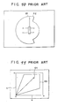
- conventional movable range indicating apparatuses for mobile crane vehicles, etc. adopt polar coordinates in which a radial direction is taken as an operating radius or a load factor, and a circumferential direction is taken as a turning angle (refer to, for example, Japanese Examined Patent Publication No. 317759, Japanese Unexamined Patent Publication No. 3-67895, and Japanese Unexamined Utility Model Publication No. 3130291).
- a rated operating radius corresponding to a current actual lifting load is calculated for each turning angle so as to be taken as the actual operating radius.
- a telescopic boom end position 61 obtained from the actual operating radius and the actual turning position, and a rated operating radius 62 (limit movable range) for each turning angle are indicated by images by superposition.
- most of the conventional apparatuses have an operation range limit function of moving the telescopic boom of the mobile crane vehicle to a desired position in advance to set the movable range, and of sounding an alarm and of limiting the action of the telescopic boom when the end of the telescopic boom reaches the boundary of the movable range during the operation. For this reason, information about the movable range of the telescopic boom cannot be obtained from the indicating apparatus, and the operator cannot grasp completely the operating radius and the turning range, so that there is a malfunction such that ensuring safety of the operation is hindered.
- an apparatus which subjects a crane to a simulation operation, allows a movable range of a revolving super structure including an operating machine to be stored, and suspends the operation of the crane and gives a warning based on the stored information (refer to, for example, Japanese Unexamined Patent Publication No. 56-75393).
- an indicating apparatus put into practical use (refer to, for example, Japanese Unexamined Patent Publication No. 558589)
- a limit movable range 63 and a telescopic boom end position 64 are indicated by superposition taking the X-coordinate a as the operating radius, and the Y-coordinate as the lift of the telescopic boom.
- the setting is usually performed with a load not being suspended, but the rated operating radius is changed by a lifting load in a load suspending operation. Therefore, even within the limited movable range, the boom may be overloaded depending upon the lifting load. That is, since a region where the boom is overloaded cannot be grasped from the movable range indicated image of the above prior art, there arises a problem in that a suitable advance measure for the prevention of the dangers cannot be taken.
- the present invention has been made to solve the problems of the prior art, and its object is to provide a mobile crane vehicle including a movable range indicating apparatus which can easily and accurately grasp a movable range of a telescopic boom end, and ensure safety of a crane operation.
- a movable range indicating apparatus comprising: a boom length detecting means; a boom angle detecting means; a turning position detecting means; a load detecting means; a movable range setting means; a target point setting means; a display section capable of indicating images in polar coordinates in which the turning angle is taken in the circumferential direction, and the operating radius is taken in the radial direction; and a control section for performing calculation based on signals from each of the means, and for outputting the calculation results to the display section, wherein the control section calculates a current actual operating radius, a current actual load, a rated operating radius for each turning position in a state of suspending the actual load, and a limit operating radius obtained by comparing the rated operating radius with an operating radius limit value set by the movable range setting means, respectively, and wherein the display section indicates the actual operating radius, the limit operating radius and the target point at the
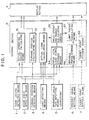
- Fig. 1 illustrates a movable range indicating apparatus which is roughly composed of each of means for performing detection, etc., a control section 8, and a display section 9.
- Each of the means comprise detecting means or inputting means, such as a boom length detecting means 1, a boom angle detecting means 2, a turning position detecting means 3, a load detecting means 4, and an operating condition inputting means (or an operating condition detecting means 5.
- a movable range setting means 6 and/or a target point setting means 7 are included as necessary.
- the above operating condition inputting (or detecting) means 5 is used for setting an operating condition before starting a crane operation, and inputs (or detects) operation modes of a revolving super structure and a base carrier.
- a revolving super structure any one of boom, single top, and jib operations is selected and inputted.
- the boom operation the number of falls of a wire rope for a load suspending hook may be inputted in addition to a normal boom operation.
- the base carrier any one of outrigger, on-tire, and suspending travel operations is selected and inputted.
- an outrigger projecting width is automatically inputted and set by an outrigger length detecting means.
- the above movable range setting means 6 is used for limiting the movable range in the crane operation, and sets the movable range responsive to an obstacle, etc.
- the setting is selected depending on the limitation of any one of crane operations, such as boom angle upper/lower limit, operating radius, boom height, boom length, and turning angle operations, and set by a setting switch.
- the setting method is performed by moving a crane vehicle in advance to an operating position to be controlled, and at the point, by pushing the setting switch corresponding to the operation to be limited. This allows the applicable operational limitation in the crane operation to be stored in a movable range storage means 56 to be described later.
- the movable range setting means includes a means for setting the range one-dimensionally or three-dimensionally.
- the setting of the above target point setting means 7 is performed by moving the crane vehicle to a predetermined operating position, by moving the boom to a target point at that point, and by pushing the setting switch.
- the set items, such as the operating radius and turning position, and a lift of the hook or a lift of the boom as necessary, are stored in a target point storage means 58 to be described later.
- control section 8 comprises an actual operating radius calculating means 51, a turning position calculating means 52, an actual load calculating means 53, a rated total load curve storage means 54, and a rated operating radium calculating means 55. Further, a movable range storage means 56, a limit radius calculating means 57, and/or a target point storage means 58 are included as necessary.
- the actual operating radius calculating means 51 calculates the actual operating radius based on the boom length and the boom angle input from the boom length detecting means 1 and the boom angle detecting means 2.
- the turning position calculating means 52 calculates the turning position from the detected value of the turning position detecting means 3.
- the above actual operating radius and the turning position become an end position of the telescopic boom, and are inputted to the display section 9.
- the actual load calculating means 53 calculates the current actual load based on the boom length, the boom angle, the load, and the operating condition obtained from the boom length detecting means 1, the boom angle detecting means 2, the load detecting means 4, and the operating condition inputting (or detecting) means 5, and outputs the actual load to the rated operating radius calculating means 55.
- the rated total load curve storage means 54 selects the applicable rated total load curve from the previously stored rated total load curves based on the boom length, the turning position, and the operating condition obtained from the boom length detecting means 1, the turning position detecting means 3, and the operating condition inputting (or detecting) means 5, and outputs it to the rated operating radius calculating means 55.
- the rated operating radius calculating means 55 calculates the rated operating radius from the actual load and the rated total load curve, and outputs it to the display section 9.
- the movable range storage means 56 which is included as necessary outputs the movable range (in this embodiment, movable range with respect to the operating radius and the turning angle) set by the movable range setting means 6 to the limit radius calculating means 57.
- the movable range in the turning angle range where turning is impossible, the movable range is outputted as the range having no movable range of the operating radius, i.e., as "0".
- the limit radius calculating means 57 compares the rated operating radius with the movable range for each turning posifion, and outputs a smaller one as the limit radius to the display section 9. That is, the limit radius calculating means 57 obtains an "AND region" between the rated operating radius and the movable range.
- an output from the rated operating radius calculating means 55 to the display section 9 is not performed.
- the rated operating radius from the rated operating radius calculating means 55, and the movable range from the movable range storage means 56 may be outputted to the display section 9 without including (or performing calculation) the limit radius calculating means 57.
- the target point storage means 58 which is included as necessary outputs the target point from the target point setting means 7 to the display section 9.
- Fig. 2 illustrates an example of the movable range indicating apparatus which comprises an operating condition inputting (or detecting) means 5 for inputting (or detecting) operation modes of the revolving super structure and the base carrier, a switch-type movable range setting means 6 for setting a boom length, and boom angle upper limit/lower limits, etc. and a display section 9 of multidisplay.
- a revolving super structure 202 is revolvably provided on a self-movable base carrier 201, and a telescopic boom 204 which is vertically swingable due to a boom cylinder 203 is mounted to the revolving super structure 202.
- the above telescopic boom 204 can extend and contract in a plurality of stages, and a hook 206 is drooped from the tip thereof through a wire 205.
- the telescopic boom 204 is provided with a boom length detecting means 1 for detecting the extension length, and a boom angle detecting means 2 for detecting the angle of the telescopic boom 204, respectively.
- a turning section of the revolving super structure 202 is provided with a turning position detecting means 3
- the boom cylinder 203 is provided with a load detecting means 4
- operating condition inputting (or detecting) means 5 are provided across the base carrier 201, respectively.
- the operating condition inputting (or detecting) means 5 in this embodiment adds a function of detecting a projecting and installation conditions of outriggers to the first embodiment. Incidentally, this addition may be performed to the above second embodiment.
- a movable range setting means 6, and as necessary, a target point setting means 7 are included in addition to the above detecting means 1 to 5.
- Information from these means 1 to 7 is inputted to a control section 8 shown in Fig. 1 to be calculated or stored, and outputted to the display section 9.
- the image is indicated in polar coordinates as described above. Examples of indication of the movable range by the described arrangements will be described.
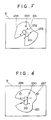
- Fig. 4 is the polar coordinates in which the operating radius is taken in the radial direction and the turning angle is taken in the circumferential direction, and the base carrier 201 which becomes the basis is indicated so as to face upward of the screen at all times.
- Numeral 230 denotes an actual operating radius (and an actual turning position), and
- numeral 231 denotes a limit operating radius with respect to the current load.
- Fig. 5 the revolving super structure 202 which becomes the basis is indicated so as to face upward of the screen at all times.
- Numeral 232 denotes a projecting condition of the outriggers
- numeral 233 denotes an installation condition of the outriggers.
- black dots show a grounding condition and open circles show a floating condition, for example.
- Fig. 6 illustrates a case where target points 236 and 237 are indicated by superposition.
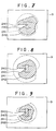
- Figs. 7 to 9 illustrates changes in the movable range when the suspended load is different, in which numeral 240 denotes a turning limit, numeral 241 denotes a rated operating radius due to the current suspended load, and numeral 242 (a diagonally shaded area) denotes a movable range.
- numeral 240 denotes a turning limit
- numeral 241 denotes a rated operating radius due to the current suspended load
- numeral 242 (a diagonally shaded area) denotes a movable range.
- dotted-line areas of the turning limit 240 and the rated operating radius 241 mean limits beyond the movable range 242. Therefore, the operator can easily perform an operation corresponding to the movable range 242, which is changed by the suspended load.
- an interference with an obstacle can be prevented by dealing with it beforehand.
- the present invention is useful as a movable range indicating apparatus for a mobile crane vehicle which enables an accurate and prompt judgement, and which can be easily operated with safety since a telescopic boom end position, a rated operating radius or a predetermined movable range, and a target point as necessary are indicated on the polar coordinates by superposition.
Landscapes
- Engineering & Computer Science (AREA)
- Mechanical Engineering (AREA)
- Jib Cranes (AREA)
Applications Claiming Priority (1)
| Application Number | Priority Date | Filing Date | Title |
|---|---|---|---|
| PCT/JP1995/000342 WO1996027548A1 (en) | 1995-03-03 | 1995-03-03 | Device for indicating movable range of mobile crane vehicle |
Related Parent Applications (1)
| Application Number | Title | Priority Date | Filing Date |
|---|---|---|---|
| EP95910734A Division EP0857687A4 (de) | 1995-03-03 | 1995-03-03 | Vorrichtung zum anzeigen von der reichweite eine mobilem kranen |
Publications (2)
| Publication Number | Publication Date |
|---|---|
| EP1306343A2 true EP1306343A2 (de) | 2003-05-02 |
| EP1306343A3 EP1306343A3 (de) | 2003-05-21 |
Family
ID=14125687
Family Applications (2)
| Application Number | Title | Priority Date | Filing Date |
|---|---|---|---|
| EP95910734A Withdrawn EP0857687A4 (de) | 1995-03-03 | 1995-03-03 | Vorrichtung zum anzeigen von der reichweite eine mobilem kranen |
| EP03090012A Withdrawn EP1306343A3 (de) | 1995-03-03 | 1995-03-03 | Autokran mit einem Reichweiteanzeigegerät |
Family Applications Before (1)
| Application Number | Title | Priority Date | Filing Date |
|---|---|---|---|
| EP95910734A Withdrawn EP0857687A4 (de) | 1995-03-03 | 1995-03-03 | Vorrichtung zum anzeigen von der reichweite eine mobilem kranen |
Country Status (4)
| Country | Link |
|---|---|
| US (1) | US5823370A (de) |
| EP (2) | EP0857687A4 (de) |
| KR (1) | KR19980702711A (de) |
| WO (1) | WO1996027548A1 (de) |
Cited By (1)
| Publication number | Priority date | Publication date | Assignee | Title |
|---|---|---|---|---|
| IT201700115700A1 (it) * | 2017-10-13 | 2019-04-13 | Hyva Holding Bv | A predictive stability control method and system for self-propelled work machines |
Families Citing this family (40)
| Publication number | Priority date | Publication date | Assignee | Title |
|---|---|---|---|---|
| DE29612377U1 (de) * | 1996-07-23 | 1996-09-12 | Kaulen, Ralf, Dipl.-Ing., 52064 Aachen | Steuervorrichtung für ein Hubrettungsfahrzeug |
| US6744372B1 (en) * | 1997-02-27 | 2004-06-01 | Jack B. Shaw | Crane safety devices and methods |
| US6894621B2 (en) * | 1997-02-27 | 2005-05-17 | Jack B. Shaw | Crane safety devices and methods |
| US6549139B2 (en) * | 1997-02-27 | 2003-04-15 | Jack B. Shaw, Jr. | Crane safety device and methods |
| CA2255111C (en) * | 1997-12-05 | 2004-11-23 | Grove U.S. L.L.C. | Aerial work platform with pothole and/or obstacle detection and avoidance system |
| US6202013B1 (en) * | 1998-01-15 | 2001-03-13 | Schwing America, Inc. | Articulated boom monitoring system |
| JP2000034093A (ja) * | 1998-07-21 | 2000-02-02 | Kobe Steel Ltd | 旋回式作業機械とその安全作業領域及び定格荷重の設定方法 |
| WO2001025549A1 (en) * | 1999-10-01 | 2001-04-12 | Hitachi Construction Machinery Co., Ltd. | Target excavation surface setting device for excavation machine, recording medium therefor and display unit |
| US6779961B2 (en) * | 2001-10-29 | 2004-08-24 | Ingersoll-Rand Company | Material handler with electronic load chart |
| DE10155006B4 (de) * | 2001-11-06 | 2004-12-16 | Terex-Demag Gmbh & Co. Kg | Fahrzeugkran mit Superlifteinrichtung |
| JP2004001987A (ja) * | 2002-03-25 | 2004-01-08 | Hitachi Constr Mach Co Ltd | 操作支援装置 |
| DE10233875B4 (de) * | 2002-07-25 | 2008-08-14 | Siemens Ag | Krananlage, insbesondere Containerkran |
| JP2004278288A (ja) * | 2003-02-26 | 2004-10-07 | Shin Caterpillar Mitsubishi Ltd | 建設機械におけるアーム角度センサ装置 |
| US6985085B1 (en) * | 2003-04-24 | 2006-01-10 | Eric Brown | Safety view blind finder for a crane |
| AT9138U1 (de) * | 2005-12-27 | 2007-05-15 | Palfinger Ag | Bedienungseinrichtung für einen ladekran |
| US7677401B2 (en) * | 2008-07-16 | 2010-03-16 | Manitowoc Crane Companies, Inc. | Load monitoring and control system with selective boom-up lockout |
| RU2399576C1 (ru) * | 2009-02-17 | 2010-09-20 | Общество с ограниченной ответственностью "Научно-производственное предприятие "Резонанс" | Устройство управления строительной машиной (варианты) |
| US8694204B2 (en) | 2009-04-17 | 2014-04-08 | Volvo Construction Equipment Ab | Vehicle and method for operating a vehicle |
| CN101670984B (zh) * | 2009-09-29 | 2012-06-06 | 长沙中联重工科技发展股份有限公司 | 单缸插销式伸缩臂轨迹的优化控制方法及控制系统 |
| DE202010014309U1 (de) * | 2010-10-14 | 2012-01-18 | Liebherr-Werk Ehingen Gmbh | Kran, insbesondere Raupen- oder Mobilkran |
| DE202010014310U1 (de) * | 2010-10-14 | 2012-01-18 | Liebherr-Werk Ehingen Gmbh | Kran, insbesondere Raupen- oder Mobilkran |
| JP5876679B2 (ja) * | 2011-07-08 | 2016-03-02 | 株式会社タダノ | 性能線表示装置 |
| EP2551233A1 (de) * | 2011-07-28 | 2013-01-30 | Gamesa Innovation & Technology, S.L. | Kran und Kransteuerungssystem |
| US9446935B2 (en) * | 2012-06-13 | 2016-09-20 | Liebherr-Werk Ehingen Gmbh | Method for monitoring crane safety and crane |
| JP2014031223A (ja) * | 2012-08-01 | 2014-02-20 | Tadano Ltd | 作業範囲図および作業範囲図表示装置 |
| JP6121670B2 (ja) * | 2012-09-05 | 2017-04-26 | 株式会社タダノ | 作業計画確認装置 |
| KR101303087B1 (ko) * | 2012-10-29 | 2013-09-04 | 김병진 | 고소작업차용 안전장치 |
| DE102013006258A1 (de) * | 2013-04-11 | 2014-10-16 | Liebherr-Components Biberach Gmbh | Kran |
| DE102014105618A1 (de) | 2014-04-22 | 2015-10-22 | Terex Cranes Germany Gmbh | Verfahren und Vorrichtung zum Betreiben eines Mobilkrans sowie Mobilkran |
| US10822208B2 (en) * | 2014-12-23 | 2020-11-03 | Manitowoc Crane Companies, Llc | Crane 3D workspace spatial techniques for crane operation in proximity of obstacles |
| US10077174B1 (en) * | 2015-04-21 | 2018-09-18 | Auto Crane Company | Automatic de-rate operating system and method for a truck mounted crane |
| CN108290722B (zh) * | 2015-10-16 | 2021-07-09 | 帕尔芬杰尔股份有限公司 | 包括控制装置和移动式控制模块的组件和液压起重设备 |
| ITUA20164597A1 (it) * | 2016-06-22 | 2017-12-22 | Iveco Magirus | Sistema di posizionamento e metodo per la determinazione di una posizione operativa di un dispositivo aereo |
| DK3333114T3 (da) * | 2016-12-07 | 2022-04-25 | Hiab Ab | Et køretøj og en fremgangsmåde til et køretøj, med præsentation af begrænsning af den maksimale belastningsradius |
| JP2018203389A (ja) * | 2017-05-30 | 2018-12-27 | 株式会社タダノ | 移動可否判別装置 |
| JP6956645B2 (ja) * | 2018-02-06 | 2021-11-02 | 住友重機械建機クレーン株式会社 | 吊荷重演算装置 |
| JP7113735B2 (ja) * | 2018-12-21 | 2022-08-05 | 住友重機械建機クレーン株式会社 | 移動式クレーン |
| WO2020256106A1 (ja) * | 2019-06-20 | 2020-12-24 | 株式会社タダノ | 可動範囲表示システムおよび可動範囲表示システムを備えるクレーン |
| IT202100023042A1 (it) * | 2021-09-07 | 2023-03-07 | Magni Real Estate S R L | Procedimento di generazione di diagrammi di carico per sollevatori telescopici |
| JP7756569B2 (ja) * | 2022-01-05 | 2025-10-20 | 住友重機械工業株式会社 | ブーム長さ推定装置及びクレーンシステム |
Family Cites Families (16)
| Publication number | Priority date | Publication date | Assignee | Title |
|---|---|---|---|---|
| FR2396720A3 (fr) * | 1977-07-07 | 1979-02-02 | Electronic Service Ets | Appareil de controle permettant de visualiser la position d'une tete de fleche de grue mobile sur un graphique ou est graduee l'aire de securite de la grue |
| JPS5556992A (en) * | 1978-10-23 | 1980-04-26 | Shinkou Tsuushin Kogyo Kk | Apparatus for preventing crane fall |
| JPS5675393A (en) * | 1979-11-20 | 1981-06-22 | Tadano Tekkosho Kk | Limiter for movable range of crane |
| JPS62111900A (ja) * | 1985-11-09 | 1987-05-22 | 株式会社豊田自動織機製作所 | 高所作業車のプラツトホ−ム表示装置 |
| RU2093452C1 (ru) * | 1988-12-27 | 1997-10-20 | Като Воркс Ко., Лтд. | Крановое предохранительное устройство |
| JPH0317759A (ja) * | 1989-06-15 | 1991-01-25 | Fujitsu Ltd | バッファメモリ制御方式 |
| JP2789231B2 (ja) * | 1989-07-31 | 1998-08-20 | 株式会社タダノ | 自走式クレーンの稼動状熊表示装置 |
| JPH085623B2 (ja) * | 1989-09-27 | 1996-01-24 | 株式会社神戸製鋼所 | クレーンの安全装置 |
| JPH03130291A (ja) * | 1989-10-16 | 1991-06-04 | Japan Tobacco Inc | ペリプラノン―b類縁体、その製造法、およびその中間体、ならびにゴキブリ類の誘引剤 |
| JPH03130291U (de) * | 1990-04-10 | 1991-12-27 | ||
| RU2096307C1 (ru) * | 1990-06-15 | 1997-11-20 | Като Воркс Ко., ЛТД | Способ определения высоты подъема крюка стрелового крана и устройство для его осуществления |
| DE4115165A1 (de) * | 1991-05-10 | 1992-11-12 | Pietzsch Automatisierungstech | Verfahren zum begrenzen des arbeitsbereichs bei einem arbeitsmittel mit einem verfahrbaren ausleger |
| JPH0558589A (ja) * | 1991-08-30 | 1993-03-09 | Kobe Steel Ltd | クレーンの安全表示装置 |
| JP3205142B2 (ja) * | 1993-09-10 | 2001-09-04 | 株式会社小松製作所 | クレーンの可動範囲表示装置 |
| JP3180996B2 (ja) * | 1993-09-10 | 2001-07-03 | 株式会社小松製作所 | クレーンの可動範囲表示装置 |
| JPH0789697A (ja) * | 1993-09-22 | 1995-04-04 | Komatsu Mec Corp | 移動式クレーンの可動範囲表示装置 |
-
1995
- 1995-03-03 EP EP95910734A patent/EP0857687A4/de not_active Withdrawn
- 1995-03-03 US US08/894,981 patent/US5823370A/en not_active Expired - Fee Related
- 1995-03-03 KR KR1019970706118A patent/KR19980702711A/ko not_active Withdrawn
- 1995-03-03 WO PCT/JP1995/000342 patent/WO1996027548A1/ja not_active Ceased
- 1995-03-03 EP EP03090012A patent/EP1306343A3/de not_active Withdrawn
Cited By (2)
| Publication number | Priority date | Publication date | Assignee | Title |
|---|---|---|---|---|
| IT201700115700A1 (it) * | 2017-10-13 | 2019-04-13 | Hyva Holding Bv | A predictive stability control method and system for self-propelled work machines |
| WO2019073456A1 (en) * | 2017-10-13 | 2019-04-18 | Hyva Holding B.V. | METHOD AND SYSTEM FOR PREDICTIVE STABILITY CONTROL FOR TRUCK MOUNTED CRANES |
Also Published As
| Publication number | Publication date |
|---|---|
| EP0857687A4 (de) | 1999-12-29 |
| US5823370A (en) | 1998-10-20 |
| EP0857687A1 (de) | 1998-08-12 |
| EP1306343A3 (de) | 2003-05-21 |
| KR19980702711A (ko) | 1998-08-05 |
| WO1996027548A1 (en) | 1996-09-12 |
Similar Documents
| Publication | Publication Date | Title |
|---|---|---|
| EP1306343A2 (de) | Autokran mit einem Reichweiteanzeigegerät | |
| US5160055A (en) | Load moment indicator system | |
| CN106715317B (zh) | 操作移动式起重机的方法与装置以及移动式起重机 | |
| US7252203B2 (en) | Mobile crane having a superlift device | |
| EP3670422B1 (de) | Mobiler kran | |
| US9783397B2 (en) | Work state monitoring device for work vehicle | |
| EP3822219B1 (de) | Kran | |
| US20220332550A1 (en) | Control system and work machine | |
| JPH01256496A (ja) | ブームを有するクレーンの吊荷地切時荷振防止装置 | |
| WO1997045358A1 (de) | Anordnung und verfahren zur lastkollisionsvermeidung bei einem hängelastbewegungsgerät | |
| JP2782235B2 (ja) | 移動式クレーンのアウトリガ反力制限信号発生装置 | |
| EP3925919A1 (de) | Hubsteuerungsvorrichtung und mobilkran | |
| EP3527526B1 (de) | Schwebstoffberechnungsvorrichtung | |
| JP2782233B2 (ja) | 移動式クレーンのアウトリガ反力表示装置 | |
| RU2271332C2 (ru) | Способ защиты стрелового грузоподъемного крана | |
| RU2271985C2 (ru) | Способ защиты грузоподъемного крана | |
| CN1177334A (zh) | 移动式起重车辆的可动范围显示装置 | |
| WO2024207782A1 (zh) | 一种塔机顶升自动配平控制方法、塔机 | |
| JPH06239584A (ja) | クレーンの吊荷位置表示装置 | |
| JPH08268681A (ja) | 作業車の作業状態模擬確認装置 | |
| JPH0789697A (ja) | 移動式クレーンの可動範囲表示装置 | |
| JP2013107762A (ja) | 旋回式作業機械の被害量表示装置 | |
| JP3180996B2 (ja) | クレーンの可動範囲表示装置 | |
| JP3205142B2 (ja) | クレーンの可動範囲表示装置 | |
| EP3925920A1 (de) | Vorrichtung zur bestimmung des dynamischen abhebens, vorrichtung zur steuerung des dynamischen abhebens, mobiler kran und verfahren zur bestimmung des dynamischen abhebens |
Legal Events
| Date | Code | Title | Description |
|---|---|---|---|
| PUAI | Public reference made under article 153(3) epc to a published international application that has entered the european phase |
Free format text: ORIGINAL CODE: 0009012 |
|
| PUAL | Search report despatched |
Free format text: ORIGINAL CODE: 0009013 |
|
| 17P | Request for examination filed |
Effective date: 20030114 |
|
| AC | Divisional application: reference to earlier application |
Ref document number: 0857687 Country of ref document: EP Kind code of ref document: P |
|
| AK | Designated contracting states |
Designated state(s): DE |
|
| AK | Designated contracting states |
Designated state(s): DE |
|
| STAA | Information on the status of an ep patent application or granted ep patent |
Free format text: STATUS: THE APPLICATION HAS BEEN WITHDRAWN |
|
| RIN1 | Information on inventor provided before grant (corrected) |
Inventor name: UEDA, MASAMICHI,C/O S.D.C.,D.D.,KOMATSU LTD. |
|
| 18W | Application withdrawn |
Effective date: 20030722 |