EP1310979A2 - Plasma impedance controlling device - Google Patents
Plasma impedance controlling device Download PDFInfo
- Publication number
- EP1310979A2 EP1310979A2 EP02022826A EP02022826A EP1310979A2 EP 1310979 A2 EP1310979 A2 EP 1310979A2 EP 02022826 A EP02022826 A EP 02022826A EP 02022826 A EP02022826 A EP 02022826A EP 1310979 A2 EP1310979 A2 EP 1310979A2
- Authority
- EP
- European Patent Office
- Prior art keywords
- frequency
- plasma impedance
- generator
- plasma
- impedance
- Prior art date
- Legal status (The legal status is an assumption and is not a legal conclusion. Google has not performed a legal analysis and makes no representation as to the accuracy of the status listed.)
- Withdrawn
Links
Images

Classifications
-
- H—ELECTRICITY
- H01—ELECTRIC ELEMENTS
- H01J—ELECTRIC DISCHARGE TUBES OR DISCHARGE LAMPS
- H01J37/00—Discharge tubes with provision for introducing objects or material to be exposed to the discharge, e.g. for the purpose of examination or processing thereof
- H01J37/32—Gas-filled discharge tubes
- H01J37/32009—Arrangements for generation of plasma specially adapted for examination or treatment of objects, e.g. plasma sources
- H01J37/32082—Radio frequency generated discharge
- H01J37/32174—Circuits specially adapted for controlling the RF discharge
-
- H—ELECTRICITY
- H01—ELECTRIC ELEMENTS
- H01J—ELECTRIC DISCHARGE TUBES OR DISCHARGE LAMPS
- H01J37/00—Discharge tubes with provision for introducing objects or material to be exposed to the discharge, e.g. for the purpose of examination or processing thereof
- H01J37/32—Gas-filled discharge tubes
- H01J37/32009—Arrangements for generation of plasma specially adapted for examination or treatment of objects, e.g. plasma sources
- H01J37/32082—Radio frequency generated discharge
-
- H—ELECTRICITY
- H01—ELECTRIC ELEMENTS
- H01J—ELECTRIC DISCHARGE TUBES OR DISCHARGE LAMPS
- H01J37/00—Discharge tubes with provision for introducing objects or material to be exposed to the discharge, e.g. for the purpose of examination or processing thereof
- H01J37/32—Gas-filled discharge tubes
- H01J37/32917—Plasma diagnostics
- H01J37/32935—Monitoring and controlling tubes by information coming from the object and/or discharge
-
- H—ELECTRICITY
- H01—ELECTRIC ELEMENTS
- H01J—ELECTRIC DISCHARGE TUBES OR DISCHARGE LAMPS
- H01J37/00—Discharge tubes with provision for introducing objects or material to be exposed to the discharge, e.g. for the purpose of examination or processing thereof
- H01J37/32—Gas-filled discharge tubes
- H01J37/34—Gas-filled discharge tubes operating with cathodic sputtering
Definitions
- the invention relates to a device for regulating a plasma impedance the preamble of claim 1.
- the so-called sputtering technique is very often used for etching and vapor deposition of substrates used, in which the ions in a vacuum chamber at low pressure of a gas are accelerated onto electrodes, where they knock out particles that then coat or etch a substrate.
- the gas ions accelerate either by means of a DC or an AC voltage on the substrate and on the electrodes.
- the entire electrical circuit consists in the Rule of an AC voltage source, a network and a plasma impedance, d. H. the impedance between the electrodes or between an electrode and the substrate. While the network usually constant electrical components possesses that do not change during operation, the plasma impedance may change by changing the proportion of ions and / or electrons relative changed to the electrically neutral particles.
- a device for controlling a sputtering system in which the electrical impedance of the plasma by regulating the strength of the magnetic field takes place (DE 34 25 659 A1).
- the cathode is supplied here with DC voltage.
- the electrical supplied to the atomizing electrode oscillates Performance between two values.
- the performance values are selected so that the target of the atomizing electrode is at the same reactive gas flow is in metallic fashion at the first power value, while at second power value is in oxidic mode. A regulation of the plasma impedance does not take place with this procedure.
- the frequency of the AC power source is adjusted during the sputtering process that the ions can still follow the alternating field, what at a frequency from about 1 kHz to 100 kHz is the case (DE 41 06 770 A1).
- a tapped discharge voltage is measured with the help of a voltage rms value as DC voltage fed to a controller, which in turn is a solenoid valve for feeding a Controls reactive gas, in such a way that the measured voltage the required Determined reactive gas amount. So it is at constant AC frequency measured a voltage, which in turn determines the reactive gas measurement.
- the invention has for its object to provide a control device with which can keep the process conditions constant.
- the invention thus relates to a device for regulating a plasma impedance in a vacuum chamber, at least one electrode with an alternating current generator communicates.
- This alternator is a cantilever, whose frequency adjusts to the resonance frequency of the load applied by it.
- This load consists of fixed switching elements and a variable one Plasma impedance. If the plasma impedance changes, so does the change Resonance frequency.
- the plasma impedance can thus be determined by detecting the resonance frequency and can be changed by specifying a frequency setpoint, e.g. B. by the voltage, the current, the power or the gas flow depending on the Difference between resonance frequency and frequency setpoint is changed.
- An advantage achieved with the invention is that the control without a sensor, for. B. an optical sensor, a ⁇ probe or a mass spectrometer, with which the plasma state is determined. Another advantage is that Si 3 N 4 processes can be controlled. In addition, the working point of the plasma process is observed exactly.
- FIG. 1 shows a sputtering system 1 which has a vacuum chamber 2, in which there are two magnetrons 3, 4.
- a vacuum chamber 2 in which there are two magnetrons 3, 4.
- upper openings 7, 8 and lower openings 9, 10 are provided, wherein in the upper openings 7, 8 vacuum pumps 11, 12 are located, while the lower Openings 9, 10 for the passage of a substrate 13, for example one Glass plate, serve through the vacuum chamber 2.
- an aperture 14 which extends from the side walls 5, 6 protrudes into the interior of the vacuum chamber 2.
- gas supply lines 15, 16 which are connected via a valve 17 with gas containers 18, 19 Connect.
- the magnetrons 3, 4 each have a cathode trough 20, 21 on their Bottom is provided with a target 22, 23. Located in the cathode tubs 20, 21 three permanent magnets 24, 25, 26 and 27, 28, 29, each with a common Yoke 30, 31 are connected.
- the cathode wells 20, 21 are in the top of the vacuum chamber via seals 32, 33 2 fitted. Both cathode wells 20, 21 are with an electrical Filter 34 connected to a medium frequency generator 35.
- this medium frequency generator 35 is not a fixed frequency oscillator or tunable oscillator, but a freely oscillating oscillator whose Frequency always matches the resonance frequency of the network connected to it.
- this cantilever chair can consist of four IGBT modules H inverter circuit exist on the network and the Plasma impedance is working. The inverter circuit is fed via a DC link in the medium frequency generator 35. This is potential-free.
- a Control electronics determined via current and voltage measurement in the output of the Inverter controls the resonant frequency of the oscillatory output the IGBT modules with this.
- the type of inverter circuit as well as that resonant control is known in medium frequency supplies (generator from Wilsontinger or the company EMA-Indutec).
- the network is made up of a medium frequency generator 35 Resonant circuit, an output transformer and outside of the generator from supply lines 36, 37, the capacitance and inductance of the filter 34 and the plasma impedance together.
- the network has the property, the stability of the process by suppressing current transients. Furthermore, with the Network the impedance value at which power matching is present can be varied what can contribute to the stabilization of the working point.
- the AC resistance is shown under plasma impedance of the plasma between the two magnetrons 3, 4 understood. If there were only one magnetron, the plasma impedance would be between them Magnetron and the substrate or another location to which the second polarity of the alternating current is connected. Because the total impedance with which the medium frequency generator 35 is loaded until the plasma impedance is constant the resonance frequency and thus the frequency with which the medium frequency generator 35 vibrates, determined by the plasma impedance. The respective actual frequency of the medium frequency generator 35 thus corresponds to the resonance frequency of the whole Circle and is therefore a function of plasma impedance. The actual frequency will a comparator 38 supplied, which also a target frequency from a target frequency generator 39 is supplied. The target frequency thus corresponds to a control technology Reference variable.
- the difference between the actual frequency and setpoint value is fed to a controller 40, which forms a control signal for the valve 17 from this difference.
- the controller 40 it can be a PI, a PID or a software fuzzy controller with a customized one Act control characteristic.
- the frequency of the cantilever changes Medium frequency generator 35 due to a change in the plasma impedance a difference between the current actual value and the setpoint from the setpoint generator and given to the controller 40. This then generates a control signal which counteracts the frequency difference, i. H. the gas inflow and thus the plasma impedance is changed in such a way that the Set target frequency.
- the medium frequency generator 35 basically oscillates and always at the resonance frequency the output from the resonant circuit, network and plasma impedance. Since all Elements in the resonant circuit and network are fixed, the resonance frequency only depends on the plasma impedance. The plasma impedance is regulated and not the frequency. The frequency is only an indirect actual value for the impedance, d. H. one changes via the manipulated variables power, current, voltage and / or gas flow the impedance, the actual value of the resonance frequency also changes.
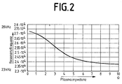
- the plasma resistance is relatively low at a resonance frequency of 2.75 ⁇ 10 4 Hz and relatively high at a resonance frequency of 2.3 ⁇ 10 4 Hz.
- the plasma impedance In order to keep the resonance frequency constant at around 2.5 ⁇ 10 4 Hz, the plasma impedance must be kept at around 4 ⁇ . If the plasma impedance changes, the regulation of the gas flow brings the plasma impedance back to its old value.
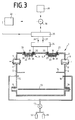
- the inflow is not of the process or reactive gas is regulated, but the electrical power of the Medium frequency generator.
- the plasma impedance is not only due to the gas inflow dependent, but also on other variables such as current, voltage and Power, a magnetic field passing through the plasma, a radiation irradiating the plasma UV radiation, the gas composition or the enrichment of the target surface with reactive gas components.
- the principle of the control according to the exemplary embodiment according to FIG. 3 is the same as in the embodiment of FIG. 1.
- the resonance frequency deviates from its Desired value, the electrical power supplied to the magnetrons 3, 4 becomes as long increases or decreases until the setpoint of the resonance frequency is reached Has.
- one process variable each - The gas inflow or electrical power - regulated.
- the invention can also can be realized with only one cathode.
- the plasma path then does not form between the two cathodes, but between the cathode and an anode.
- the anode can be through the vacuum chamber 2 or through one in the vacuum chamber 2 suspended insulated electrodes are formed.
- the working point to be set depends on the demands placed on the layer that is deposited on the substrate 13.
Landscapes
- Physics & Mathematics (AREA)
- Engineering & Computer Science (AREA)
- Plasma & Fusion (AREA)
- Chemical & Material Sciences (AREA)
- Analytical Chemistry (AREA)
- Plasma Technology (AREA)
- Physical Vapour Deposition (AREA)
- Drying Of Semiconductors (AREA)
- Physical Or Chemical Processes And Apparatus (AREA)
Abstract
Description
Die Erfindung betrifft eine Einrichtung für die Regelung einer Plasmaimpedanz nach
dem Oberbegriff des Patentanspruchs 1.The invention relates to a device for regulating a plasma impedance
the preamble of
Zum Ätzen und Bedampfen von Substraten wird sehr oft die so genannte Sputtertechnik eingesetzt, bei welcher in einer Vakuumkammer bei niedrigem Druck die Ionen eines Gases auf Elektroden beschleunigt werden, wo sie Partikel herausschlagen, die dann ein Substrat beschichten oder ätzen. Die Beschleunigung der Gas-Ionen erfolgt entweder mittels einer Gleich- oder einer Wechselspannung, die am Substrat und an den Elektroden liegt.The so-called sputtering technique is very often used for etching and vapor deposition of substrates used, in which the ions in a vacuum chamber at low pressure of a gas are accelerated onto electrodes, where they knock out particles that then coat or etch a substrate. The gas ions accelerate either by means of a DC or an AC voltage on the substrate and on the electrodes.
Wird eine Wechselspannung angelegt, so besteht der gesamte elektrische Kreis in der Regel aus einer Wechselspannungsquelle, einem Netzwerk und einer Plasmaimpedanz, d. h. der Impedanz zwischen den Elektroden bzw. zwischen einer Elektrode und dem Substrat. Während das Netzwerk in der Regel konstante elektrische Bauelemente besitzt, die sich während des Betriebs nicht verändern, kann sich die Plasmaimpedanz dadurch ändern, dass sich der Anteil der Ionen und/oder Elektronen relativ zu den elektrisch neutralen Partikeln verändert.If an AC voltage is applied, the entire electrical circuit consists in the Rule of an AC voltage source, a network and a plasma impedance, d. H. the impedance between the electrodes or between an electrode and the substrate. While the network usually constant electrical components possesses that do not change during operation, the plasma impedance may change by changing the proportion of ions and / or electrons relative changed to the electrically neutral particles.
Will man beim reaktiven Mittelfrequenz-Sputtern eine hohe Sputterrate erzielen, ist es erforderlich, im Übergangsbereich zwischen dem metallischen und dem voll reaktiven Mode zu arbeiten. Dabei soll der Betrieb stabil bleiben. Bei großen Leistungen und/oder Kathodenlängen ist ein stabiler Betrieb im Übergangsbereich allerdings oft schwer erzielbar, weil leicht ein unkontrolliertes Kippen vom metallischen in den voll reaktiven Mode und umgekehrt erfolgt.If you want to achieve a high sputtering rate with reactive medium-frequency sputtering, is it is necessary in the transition area between the metallic and the fully reactive Work fashion. The operation should remain stable. For great performances and / or cathode lengths is often stable operation in the transition area difficult to achieve, because an uncontrolled tipping from the metal into the fully reactive fashion and vice versa.
Es ist bekannt, dass die Impedanz vor der Zündung des Plasmas annähernd unendlich groß ist und sich nach der Zündung, abhängig vom Arbeitspunkt, auf einen Wert > 0 Ω einstellt. Außerdem ist bekannt, dass das vorbeschriebene System aus Wechselspannungsquelle, Netzwerk und Plasmaimpedanz einen Resonanzkreis darstellt, dessen Resonanzfrequenz sich mit der Plasmaimpedanz ändert (Society of Vacuum Coaters, Konferenzbeitrag Hüttinger Elektronik, 1999). Mittel, mit denen ein stabiler Sputterbetrieb erzielt werden kann, sind in dieser Veröffentlichung nicht angegeben. Vielmehr ist lediglich der Zustand beschrieben, der sich im ungeregelten Zustand bei Vorgabe der Prozessparameter Leistung und Gasflüsse einstellt. Dieser Zustand definiert einen bestimmten Arbeitspunkt bei einer bestimmten Plasmaimpedanz und damit eine bestimmte Resonanzfrequenz.It is known that the impedance before the ignition of the plasma is almost infinite is large and after ignition, depending on the working point, to a value > 0 Ω. It is also known that the system described above from an AC voltage source, Network and plasma impedance represents a resonance circuit, whose resonance frequency changes with the plasma impedance (Society of Vacuum Coaters, conference contribution Hüttinger Elektronik, 1999). Means with which a stable Sputter operation can be achieved are not specified in this publication. Rather, only the state is described that occurs in the unregulated state Specification of the process parameters power and gas flows. This state defines a certain operating point with a certain plasma impedance and thus a certain resonance frequency.
Weiterhin ist eine Einrichtung zum Regeln einer Sputteranlage bekannt, bei welcher
die elektrische Impedanz des Plasmas durch Regeln der Stärke des magnetischen Feldes
erfolgt (DE 34 25 659 A1). Die Speisung der Kathode erfolgt hierbei allerdings
mit Gleichspannung.Furthermore, a device for controlling a sputtering system is known, in which
the electrical impedance of the plasma by regulating the strength of the magnetic field
takes place (
Bei einem anderen bekannten Verfahren zum Beschichten eines Substrats mittels einer
Sputtervorrichtung soll der Arbeitspunkt schnell und einfach stabilisiert werden
(EP 0 795 890 A2). Hierbei pendelt die der Zerstäubungselektrode zugeführte elektrische
Leistung zwischen zwei Werten. Die Leistungswerte werden dabei so ausgewählt,
dass sich bei gleichem Reaktivgaszufluss das Target der Zerstäubungselektrode
beim ersten Leistungswert im metallischen Mode befindet, während es sich beim
zweiten Leistungswert im oxidischen Mode befindet. Eine Regelung der Plasmaimpedanz
findet bei diesem Verfahren nicht statt.In another known method for coating a substrate by means of a
Sputtering device should stabilize the working point quickly and easily
(
Eine Stabilisierung eines Mittelfrequenz-Sputterprozesses ohne externe Regelung, bei welcher die Netzwerkanpassung so gewählt ist, dass den Störungen entgegengewirkt wird, ist ebenfalls bekannt (DE 195 37 212 A1 = US-PS 5 807 470).A stabilization of a medium frequency sputtering process without external control, at which the network adaptation is selected so that the interference counteracts is also known (DE 195 37 212 A1 = US Pat. No. 5,807,470).
Es sind außerdem ein Verfahren und eine Anlage zur Beschichtung mindestens eines
Gegenstands mit mindestens einer Schicht bekannt, wobei ein ohmisch leitendes Target
in einer mittels Gleichstrom und diesem überlagertem Wechselstrom betriebenen
Glimmentladung zerstäubt wird (EP 0 508 359 A1). Der Beschichtungsprozess wird
dabei im instabilen Übergangsmode zwischen metallischem und reaktivem Mode betrieben.
Durch Regelung wird dieser Prozess im instabilen Übergangsmode stabil
siert, und zwar im Übergangsmode in der Nähe zum Übergang in den metallischen
Mode. Als Stellgrößen werden im Regelkreis das Gleichstromsignal und/oder die
Frequenz des Gleichstromsignals und/oder die Frequenz und/oder die Amplitude des
Wechselstromsignals eingesetzt. Die Istwert-Erfassung erfolgt durch ein optisches
Verfahren, insbesondere durch Absorptions- und/oder Fluoreszenzspektroskopie.
Eine derartige Istwert-Erfassung ist relativ aufwändig.There is also a method and an installation for coating at least one
Object known with at least one layer, wherein an ohmic conductive target
in a operated with direct current and superimposed alternating current
Glow discharge is atomized (
Bei einem anderen bekannten Verfahren zum reaktiven Beschichten eines Substrats wird die Frequenz der Wechselstromquelle während des Sputterprozesses so eingestellt, dass die Ionen dem Wechselfeld noch folgen können, was bei einer Frequenz von etwa 1 kHz bis 100 kHz der Fall ist (DE 41 06 770 A1). Eine abgegriffene Entladespannung wird mit Hilfe einer Spannungseffektivwerterfassung als Gleichspannung einem Regler zugeführt, der wiederum ein Magnetventil für die Zuführung eines Reaktivgases ansteuert, und zwar derart, dass die gemessene Spannung die erforderliche Reaktivgasmenge bestimmt. Es wird also bei konstanter Wechselstromfrequenz eine Spannung gemessen, die ihrerseits die Reaktivgasmessung festlegt.In another known method for reactive coating of a substrate the frequency of the AC power source is adjusted during the sputtering process that the ions can still follow the alternating field, what at a frequency from about 1 kHz to 100 kHz is the case (DE 41 06 770 A1). A tapped discharge voltage is measured with the help of a voltage rms value as DC voltage fed to a controller, which in turn is a solenoid valve for feeding a Controls reactive gas, in such a way that the measured voltage the required Determined reactive gas amount. So it is at constant AC frequency measured a voltage, which in turn determines the reactive gas measurement.
Weiterhin ist eine Balanceregelung für reaktives Magnetronsputtern zur optischen Großflächenbeschichtung bekannt, bei welcher die Instabilität des Übergangsbereichs zwischen dem metallischen Arbeitsbereich und dem oxidischen Arbeitsbereich durch eine Regelung verringert oder beseitigt wird (C. May und J. Strümpfel: Balanceregelung für reaktives Magnetronsputtern zur optischen Großflächenbeschichtung, Vakuum in Forschung und Praxis, 2001, Nr. 2, S. 79 bis 84). Hierbei werden für die Istwert-Erfassung die optische Spektroskopie, die Partialdruckmessung und die Plasmaimpedanz herangezogen. Die Regelung der Plasmaimpedanz erfolgt über die Entladespannung, die zur Beibehaltung der von einer Mittelfrequenz-Stromversorgung konstant gehaltenen Leistung erforderlich ist. Eine Frequenzveränderung der Spannung findet indessen nicht statt.Furthermore, there is a balance control for reactive magnetron sputtering for optical Large area coating is known, in which the instability of the transition area between the metallic working area and the oxidic working area a regulation is reduced or eliminated (C. May and J. Strümpfel: balance regulation for reactive magnetron sputtering for optical coating of large areas, vacuum in Research and Practice, 2001, No. 2, pp. 79 to 84). Here, for the actual value acquisition optical spectroscopy, partial pressure measurement and plasma impedance used. The plasma impedance is regulated via the discharge voltage, which is to maintain the from a medium frequency power supply constant power is required. A change in frequency of the voltage however, does not take place.
Schließlich ist auch noch ein Hochleistungsgenerator für das Mittelfrequenz-Sputtern mit Doppelmagnetron bekannt, der eine hohe Leistungsstabilität und eine Anpassung an verschiedene Lastimpedanzen gewährleistet (T. Rettich, P. Wiedemuth: High power generators for medium frequency sputtering applications, Journal of Non-Crystalline Solids 218, 1997, S. 50 bis 53). Dieser Oszillator weist einen Resonanzkreis auf und kann Spannungen von 300 V bis zu mehr als 1200 V bereitstellen. Sein Frequenzbereich geht von 20 bis 100 kHz. In Abhängigkeit von dem zu sputternden Material wird die jeweils optimale Frequenz eingestellt. Entsprechend einer besonderen Auslegung des frei schwingenden Oszillators erfolgt die Reaktion auf Lastschwankungen innerhalb einer Halbwelle. Laständerungen resultieren sofort in Frequenzänderungen, wodurch eine Fehlanpassung vermieden wird. Diese Frequenzänderung wird jedoch nicht als Messgröße zur Istwert-Erfassung der zu regelnden Systemimpedanz genutzt.Finally, there is also a high-performance generator for medium-frequency sputtering known with double magnetron, which has high performance stability and adjustment guaranteed at different load impedances (T. Rettich, P. Wiedemuth: High power generators for medium frequency sputtering applications, Journal of Non-Crystalline Solids 218, 1997, pp. 50 to 53). This oscillator has a resonant circuit and can provide voltages from 300 V up to more than 1200 V. His Frequency range goes from 20 to 100 kHz. Depending on the sputtered Material the optimal frequency is set. According to a special one The free oscillating oscillator is designed to respond to load fluctuations within a half wave. Load changes immediately result in frequency changes, thereby avoiding mismatch. This frequency change However, it is not used as a measurand for the actual value acquisition of the system to be controlled System impedance used.
Der Erfindung liegt die Aufgabe zugrunde, eine Regeleinrichtung zu schaffen, mit der die Prozessbedingungen konstant gehalten werden können.The invention has for its object to provide a control device with which can keep the process conditions constant.
Diese Aufgabe wird gemäß den Merkmalen des Patentanspruchs 1 gelöst.This object is achieved in accordance with the features of
Die Erfindung betrifft somit eine Einrichtung zum Regeln einer Plasmaimpedanz in einer Vakuumkammer, wobei wenigstens eine Elektrode mit einem Wechselstromgenerator in Verbindung steht. Dieser Wechselstromgenerator ist ein Freischwinger, dessen Frequenz sich auf die Resonanzfrequenz der von ihm beaufschlagten Last einstellt. Diese Last besteht aus festen Schaltelementen und aus einer variablen Plasmaimpedanz. Ändert sich die Plasmaimpedanz, ändert sich mit ihr auch die Resonanzfrequenz. Die Plasmaimpedanz kann somit durch Erfassung der Resonanzfrequenz und durch Vorgabe eines Frequenz-Sollwerts verändert werden, z. B. indem die Spannung, der Strom, die Leistung oder der Gaszufluss in Abhängigkeit von der Differenz zwischen Resonanzfrequenz und Frequenz-Sollwert verändert wird.The invention thus relates to a device for regulating a plasma impedance in a vacuum chamber, at least one electrode with an alternating current generator communicates. This alternator is a cantilever, whose frequency adjusts to the resonance frequency of the load applied by it. This load consists of fixed switching elements and a variable one Plasma impedance. If the plasma impedance changes, so does the change Resonance frequency. The plasma impedance can thus be determined by detecting the resonance frequency and can be changed by specifying a frequency setpoint, e.g. B. by the voltage, the current, the power or the gas flow depending on the Difference between resonance frequency and frequency setpoint is changed.
Ein mit der Erfindung erzielter Vorteil besteht darin, dass die Regelung ohne einen Sensor, z. B. einen optischen Sensor, eine λ-Sonde oder ein Massenspektrometer, auskommt, mit dem der Plasmazustand festgestellt wird. Ein weiterer Vorteil besteht darin, dass Si3N4-Prozesse geregelt werden können. Außerdem wird der Arbeitspunkt des Plasmaprozesses exakt eingehalten.An advantage achieved with the invention is that the control without a sensor, for. B. an optical sensor, a λ probe or a mass spectrometer, with which the plasma state is determined. Another advantage is that Si 3 N 4 processes can be controlled. In addition, the working point of the plasma process is observed exactly.
Ausführungsbeispiele der Erfindung sind in den Zeichnungen dargestellt und werden im Folgenden näher beschrieben. Es zeigen:
- Fig. 1
- eine erste Ausführungsform der Erfindung, bei welcher die Impedanz durch Steuerung des Zuflusses von Prozess- und/oder Reaktivgas geregelt wird;
- Fig. 2
- eine Kennliniendarstellung, die den Zusammenhang zwischen Plasmaimpedanz und Resonanzfrequenz zeigt;
- Fig. 3
- eine zweite Ausführungsform der Erfindung, bei welcher die Impedanz durch Steuerung der Spannung, des Stroms und/oder der Leistung geregelt werden.
- Fig. 1
- a first embodiment of the invention, in which the impedance is regulated by controlling the inflow of process and / or reactive gas;
- Fig. 2
- a graph showing the relationship between plasma impedance and resonance frequency;
- Fig. 3
- a second embodiment of the invention, in which the impedance is regulated by controlling the voltage, the current and / or the power.
In der Fig. 1 ist eine Sputteranlage 1 dargestellt, die eine Vakuumkammer 2 aufweist,
in der sich zwei Magnetrons 3, 4 befinden. In Seitenwänden 5, 6 der Vakuumkammer
2 sind obere Öffnungen 7, 8 und untere Öffnungen 9, 10 vorgesehen, wobei sich in
den oberen Öffnungen 7, 8 Vakuumpumpen 11, 12 befinden, während die unteren
Öffnungen 9, 10 zur Durchschleusung eines Substrats 13, beispielsweise einer
Glasplatte, durch die Vakuumkammer 2 dienen. Zwischen den unteren Öffnungen 9,
10 und den oberen Öffnungen 7, 8 befindet sich eine Blende 14, die von den Seitenwänden
5, 6 in das Innere der Vakuumkammer 2 ragt. Unterhalb dieser Blende 14 befinden
sich Gaszuführungen 15, 16, die über ein Ventil 17 mit Gasbehältern 18, 19 in
Verbindung stehen.1 shows a
Die Magnetrons 3, 4 weisen jeweils eine Kathodenwanne 20, 21 auf, die auf ihrer
Unterseite mit einem Target 22, 23 versehen ist. In den Kathodenwannen 20, 21 befinden
sich jeweils drei Dauermagnete 24, 25, 26 bzw. 27, 28, 29, die mit einem gemeinsamen
Joch 30, 31 verbunden sind.The
Die Kathodenwannen 20, 21 sind über Dichtungen 32, 33 in die Oberseite der Vakuumkammer
2 eingepasst. Beide Kathodenwannen 20, 21 sind mit einem elektrischen
Filter 34 verbunden, das an einem Mittelfrequenzgenerator 35 liegt. Bei diesem Mittelfrequenzgenerator
35 handelt es sich nicht um einen Festfrequenzoszillator oder
durchstimmbaren Oszillator, sondern um einen frei schwingenden Oszillator, dessen
Frequenz stets mit der Resonanzfrequenz des mit ihm verbundenen Netzwerks übereinstimmt.
Im Einzelnen kann dieser Freischwinger aus einer vier IGBT-Module enthaltenden
H-Wechselrichterschaltung bestehen, die auf das Netzwerk und die
Plasmaimpedanz arbeitet. Gespeist wird die Wechselrichterschaltung über einen
Gleichstromzwischenkreis im Mittelfrequenzgenerator 35. Dieser ist potentialfrei. Eine
Steuerelektronik ermittelt über Strom- und Spannungsmessung im Ausgang des
Wechselrichters die Resonanzfrequenz des schwingungsfähigen Ausgangs und steuert
die IGBT-Module mit dieser an. Die Art der Wechselrichterschaltung sowie das
resonante Ansteuern ist bei Mittelfrequenzversorgungen bekannt (Generator der Fa.
Hüttinger oder der Fa. EMA-Indutec).The
Das Netzwerk setzt sich innerhalb des Mittelfrequenzgenerators 35 aus einem
Schwingkreis, einem Ausgangstransformator und außerhalb des Generators aus Zuführungsleitungen
36, 37, der Kapazität und Induktivität des Filters 34 und der Plasmaimpedanz
zusammen. Das Netzwerk hat die Eigenschaft, die Stabilität des Prozesses
durch Unterdrückung von Stromtransienten zu erhöhen. Weiterhin kann mit dem
Netzwerk der Impedanzwert, bei dem Leistungsanpassung vorliegt, variiert werden,
was zur Arbeitspunktstabilisierung beitragen kann.The network is made up of a
Unter Plasmaimpedanz wird bei dem Ausführungsbeispiel der Fig. 1 der Wechselstromwiderstand
des Plasmas zwischen den beiden Magnetrons 3, 4 verstanden.
Wäre nur ein Magnetron vorhanden, läge die Plasmaimpedanz zwischen diesem
Magnetron und dem Substrat oder einer anderen Stelle, an welche die zweite Polarität
des Wechselstroms angeschlossen ist. Da die Gesamtimpedanz, mit welcher der Mittelfrequenzgenerator
35 belastet wird, bis auf die Plasmaimpedanz konstant ist, wird
die Resonanzfrequenz und damit die Frequenz, mit welcher der Mittelfrequenzgenerator
35 schwingt, durch die Plasmaimpedanz bestimmt. Die jeweilige Ist-Frequenz
des Mittelfrequenzgenerators 35 entspricht somit der Resonanzfrequenz des ganzen
Kreises und ist folglich eine Funktion der Plasmaimpedanz. Die Ist-Frequenz wird
einem Vergleicher 38 zugeführt, dem auch eine Soll-Frequenz aus einem Soll-Frequenzgeber
39 zugeführt wird. Die Soll-Frequenz entspricht also einer regelungstechnischen
Führungsgröße.In the exemplary embodiment of FIG. 1, the AC resistance is shown under plasma impedance
of the plasma between the two
Die Differenz zwischen Frequenz-Ist- und -Sollwert wird einem Regler 40 zugeführt,
der aus dieser Differenz ein Steuersignal für das Ventil 17 bildet. Bei dem Regler 40
kann es sich um einen PI-, einen PID- oder einen Software-Fuzzy-Regler mit angepasster
Regelcharakteristik handeln. Ändert sich die Frequenz des freischwingenden
Mittelfrequenzgenerators 35 aufgrund einer Änderung der Plasmaimpedanz, wird
durch den Differenzbildner 38 eine Differenz zwischen dem aktuellen Istwert und
dem Sollwert aus dem Sollwertgeber gebildet und an den Regler 40 gegeben. Dieser
erzeugt hierauf ein Regelsignal, welches der Frequenz-Differenz entgegenwirkt, d. h.
der Gaszustrom und damit die Plasmaimpedanz wird derart verändert, dass sich die
Soll-Frequenz einstellt.The difference between the actual frequency and setpoint value is fed to a
Der Mittelfrequenzgenerator 35 schwingt grundsätzlich und immer auf der Resonanzfrequenz
des Ausgangs aus Schwingkreis, Netzwerk und Plasmaimpedanz. Da alle
Elemente in Schwingkreis und Netzwerk fest sind, hängt die Resonanzfrequenz nur
von der Plasmaimpedanz ab. Geregelt wird die Plasmaimpedanz und nicht die Frequenz.
Die Frequenz stellt lediglich einen indirekten Istwert für die Impedanz dar,
d. h. ändert man über die Stellgrößen Leistung, Strom, Spannung und/oder Gasfluss
die Impedanz, so ändert sich auch der Istwert der Resonanzfrequenz.The
In der Fig. 2 ist die Kennlinie dargestellt, die den Zusammenhang zwischen der Plasmaimpedanz und der Frequenz zeigt. Man erkennt hieraus, dass der Plasmawiderstand bei einer Resonanzfrequenz von 2.75 · 104 Hz relativ niedrig und bei einer Resonanzfrequenz von 2.3 · 104 Hz relativ hoch ist. Um die Resonanzfrequenz etwa bei 2.5 · 104 Hz konstant zu halten, muss die Plasmaimpedanz auf etwa 4 Ω gehalten werden. Verändert sich die Plasmaimpedanz, so wird durch die Regelung des Gaszuflusses die Plasmaimpedanz wieder auf ihren alten Wert gebracht.2 shows the characteristic curve which shows the relationship between the plasma impedance and the frequency. It can be seen from this that the plasma resistance is relatively low at a resonance frequency of 2.75 · 10 4 Hz and relatively high at a resonance frequency of 2.3 · 10 4 Hz. In order to keep the resonance frequency constant at around 2.5 · 10 4 Hz, the plasma impedance must be kept at around 4 Ω. If the plasma impedance changes, the regulation of the gas flow brings the plasma impedance back to its old value.
Die Fig. 3 zeigt eine Ausführungsform der Erfindung, bei welcher nicht der Zufluss des Prozess- oder Reaktivgases geregelt wird, sondern die elektrische Leistung des Mittelfrequenzgenerators. Die Plasmaimpedanz ist nämlich nicht nur von dem Gaszufluss abhängig, sondern auch noch von anderen Größen wie Strom, Spannung und Leistung, einem das Plasma durchsetzenden Magnetfeld, einer das Plasma bestrahlenden UV-Strahlung, der Gaszusammensetzung oder der Anreicherung der Targetoberfläche mit Reaktivgasanteilen.3 shows an embodiment of the invention in which the inflow is not of the process or reactive gas is regulated, but the electrical power of the Medium frequency generator. The plasma impedance is not only due to the gas inflow dependent, but also on other variables such as current, voltage and Power, a magnetic field passing through the plasma, a radiation irradiating the plasma UV radiation, the gas composition or the enrichment of the target surface with reactive gas components.
Das Prinzip der Regelung gemäß dem Ausführungsbeispiel nach Fig. 3 ist das gleiche
wie bei dem Ausführungsbeispiel nach Fig. 1. Weicht die Resonanzfrequenz von ihrem
Sollwert ab, wird die den Magnetrons 3, 4 zugeführte elektrische Leistung solange
vergrößert oder verkleinert, bis sich der Sollwert der Resonanzfrequenz eingestellt
hat.The principle of the control according to the exemplary embodiment according to FIG. 3 is the same
as in the embodiment of FIG. 1. The resonance frequency deviates from its
Desired value, the electrical power supplied to the
Bei den vorstehend beschriebenen Ausführungsbeispielen wurde jeweils eine Prozessvariable - der Gaszufluss bzw. die elektrische Leistung - geregelt. Es ist jedoch auch möglich, mehrere Prozessvariablen kombiniert zu regeln. Wesentlich ist nur, dass die Regelvorgänge die Ist-Frequenz des freischwingenden Mittelfrequenzgenerators auf die Soll-Frequenz bringen.In the exemplary embodiments described above, one process variable each - The gas inflow or electrical power - regulated. However, it is It is also possible to control several process variables in combination. The only important thing is that the control processes the actual frequency of the free-swinging medium frequency generator bring to the target frequency.
Statt zweier Kathoden, wie in den Fig. 1 und 3 dargestellt, kann die Erfindung auch
mit nur einer Kathode realisiert werden. Die Plasmastrecke bildet sich dann nicht
zwischen den beiden Kathoden, sondern zwischen der Kathode und einer Anode aus.
Die Anode kann hierbei durch die Vakuumkammer 2 oder durch eine in der Vakuumkammer
2 aufgehängte isolierte Elektrode gebildet werden. Der einzustellende Arbeitspunkt
hängt von den Anforderungen ab, die an die Schicht gestellt werden, die
sich auf dem Substrat 13 niederschlägt.Instead of two cathodes, as shown in FIGS. 1 and 3, the invention can also
can be realized with only one cathode. The plasma path then does not form
between the two cathodes, but between the cathode and an anode.
The anode can be through the
Claims (9)
Applications Claiming Priority (2)
| Application Number | Priority Date | Filing Date | Title |
|---|---|---|---|
| DE10154229A DE10154229B4 (en) | 2001-11-07 | 2001-11-07 | Device for the regulation of a plasma impedance |
| DE10154229 | 2001-11-07 |
Publications (2)
| Publication Number | Publication Date |
|---|---|
| EP1310979A2 true EP1310979A2 (en) | 2003-05-14 |
| EP1310979A3 EP1310979A3 (en) | 2006-03-29 |
Family
ID=7704642
Family Applications (1)
| Application Number | Title | Priority Date | Filing Date |
|---|---|---|---|
| EP02022826A Withdrawn EP1310979A3 (en) | 2001-11-07 | 2002-10-12 | Plasma impedance controlling device |
Country Status (4)
| Country | Link |
|---|---|
| US (1) | US6860973B2 (en) |
| EP (1) | EP1310979A3 (en) |
| JP (1) | JP2003234200A (en) |
| DE (1) | DE10154229B4 (en) |
Cited By (1)
| Publication number | Priority date | Publication date | Assignee | Title |
|---|---|---|---|---|
| WO2007147582A1 (en) * | 2006-06-20 | 2007-12-27 | Fraunhofer-Gesellschaft zur Förderung der angewandten Forschung e.V. | Method for controlling a reactive high-power pulsed magnetron sputter process and corresponding device |
Families Citing this family (17)
| Publication number | Priority date | Publication date | Assignee | Title |
|---|---|---|---|---|
| DE10154229B4 (en) | 2001-11-07 | 2004-08-05 | Applied Films Gmbh & Co. Kg | Device for the regulation of a plasma impedance |
| KR20060064047A (en) * | 2003-08-08 | 2006-06-12 | 세키스이가가쿠 고교가부시키가이샤 | Plasma processing method and apparatus |
| JP2005063760A (en) * | 2003-08-08 | 2005-03-10 | Sekisui Chem Co Ltd | Plasma processing method and processing apparatus |
| US20060172536A1 (en) * | 2005-02-03 | 2006-08-03 | Brown Karl M | Apparatus for plasma-enhanced physical vapor deposition of copper with RF source power applied through the workpiece |
| US7262606B2 (en) | 2005-03-26 | 2007-08-28 | Huettinger Elektronik Gmbh + Co. Kg | Method of arc detection |
| US20060278524A1 (en) * | 2005-06-14 | 2006-12-14 | Stowell Michael W | System and method for modulating power signals to control sputtering |
| US20070095281A1 (en) * | 2005-11-01 | 2007-05-03 | Stowell Michael W | System and method for power function ramping of microwave liner discharge sources |
| US7842355B2 (en) * | 2005-11-01 | 2010-11-30 | Applied Materials, Inc. | System and method for modulation of power and power related functions of PECVD discharge sources to achieve new film properties |
| JP2007326051A (en) * | 2006-06-08 | 2007-12-20 | Toshiba Corp | Discharge gas treatment apparatus and gas treatment method therefor |
| JP4436350B2 (en) | 2006-09-14 | 2010-03-24 | 株式会社アルバック | Thin film forming method and thin film forming apparatus |
| DE102011076404B4 (en) | 2011-05-24 | 2014-06-26 | TRUMPF Hüttinger GmbH + Co. KG | A method of impedance matching the output impedance of a high frequency power supply arrangement to the impedance of a plasma load and high frequency power supply arrangement |
| EP4017223B1 (en) | 2017-06-27 | 2025-10-15 | Canon Anelva Corporation | Plasma processing apparatus |
| CN114666965B (en) | 2017-06-27 | 2025-08-01 | 佳能安内华股份有限公司 | Plasma processing apparatus |
| PL3648554T3 (en) | 2017-06-27 | 2021-11-22 | Canon Anelva Corporation | PLASMA PROCESSING DEVICE |
| EP3648550B1 (en) | 2017-06-27 | 2021-06-02 | Canon Anelva Corporation | Plasma treatment device |
| PL3817517T3 (en) * | 2018-06-26 | 2024-10-28 | Canon Anelva Corporation | Plasma treatment device, plasma treatment method, program, and memory medium |
| CN117004917B (en) * | 2023-08-14 | 2025-08-15 | 天津吉兆源科技有限公司 | Uniformity adjusting device and magnetron sputtering vacuum coating machine |
Family Cites Families (16)
| Publication number | Priority date | Publication date | Assignee | Title |
|---|---|---|---|---|
| CA1242989A (en) * | 1983-07-19 | 1988-10-11 | Donald R. Boys | Apparatus for and method of controlling sputter coating |
| US4500408A (en) | 1983-07-19 | 1985-02-19 | Varian Associates, Inc. | Apparatus for and method of controlling sputter coating |
| JPS6180858A (en) * | 1984-09-28 | 1986-04-24 | Hitachi Ltd | Power mosfet |
| JPH0673319B2 (en) * | 1987-01-26 | 1994-09-14 | 三菱電機株式会社 | Plasma equipment |
| DE4106770C2 (en) * | 1991-03-04 | 1996-10-17 | Leybold Ag | Performing reactive coating of a substrate |
| ATE144004T1 (en) | 1991-04-12 | 1996-10-15 | Balzers Hochvakuum | METHOD AND SYSTEM FOR COATING AT LEAST ONE OBJECT |
| JP3251087B2 (en) * | 1993-02-16 | 2002-01-28 | 東京エレクトロン株式会社 | Plasma processing equipment |
| JPH0772307A (en) * | 1993-09-03 | 1995-03-17 | Canon Inc | Thin film forming method and apparatus |
| DE19537212A1 (en) | 1994-10-06 | 1996-04-11 | Leybold Ag | Apparatus for sputter coating substrates which is self-stabilising even at high power |
| JP2884056B2 (en) * | 1995-12-07 | 1999-04-19 | パール工業株式会社 | High frequency power supply for generating discharge plasma and semiconductor manufacturing apparatus |
| DE19610012B4 (en) * | 1996-03-14 | 2005-02-10 | Unaxis Deutschland Holding Gmbh | A method for stabilizing a working point in reactive sputtering in an oxygen-containing atmosphere |
| JPH1183907A (en) * | 1997-09-03 | 1999-03-26 | Mitsubishi Electric Corp | How to measure high frequency current |
| JP3296425B2 (en) * | 1999-03-10 | 2002-07-02 | サンケン電気株式会社 | Power converter |
| JP3959200B2 (en) * | 1999-03-19 | 2007-08-15 | 株式会社東芝 | Semiconductor device manufacturing equipment |
| CN1241316C (en) * | 1999-07-13 | 2006-02-08 | 东京电子株式会社 | RF power supply for generating inductively coupled plasma |
| DE10154229B4 (en) | 2001-11-07 | 2004-08-05 | Applied Films Gmbh & Co. Kg | Device for the regulation of a plasma impedance |
-
2001
- 2001-11-07 DE DE10154229A patent/DE10154229B4/en not_active Expired - Fee Related
-
2002
- 2002-10-12 EP EP02022826A patent/EP1310979A3/en not_active Withdrawn
- 2002-11-01 JP JP2002319971A patent/JP2003234200A/en active Pending
- 2002-11-04 US US10/287,452 patent/US6860973B2/en not_active Expired - Fee Related
Cited By (1)
| Publication number | Priority date | Publication date | Assignee | Title |
|---|---|---|---|---|
| WO2007147582A1 (en) * | 2006-06-20 | 2007-12-27 | Fraunhofer-Gesellschaft zur Förderung der angewandten Forschung e.V. | Method for controlling a reactive high-power pulsed magnetron sputter process and corresponding device |
Also Published As
| Publication number | Publication date |
|---|---|
| US6860973B2 (en) | 2005-03-01 |
| EP1310979A3 (en) | 2006-03-29 |
| JP2003234200A (en) | 2003-08-22 |
| US20030087044A1 (en) | 2003-05-08 |
| DE10154229A1 (en) | 2003-05-15 |
| DE10154229B4 (en) | 2004-08-05 |
Similar Documents
| Publication | Publication Date | Title |
|---|---|---|
| DE10154229B4 (en) | Device for the regulation of a plasma impedance | |
| DE19610012B4 (en) | A method for stabilizing a working point in reactive sputtering in an oxygen-containing atmosphere | |
| EP2140476B1 (en) | Vacuum arc vaporization source, and an arc vaporization chamber with a vacuum arc vaporization source | |
| EP1869690B2 (en) | Method for operating a pulsed arc source | |
| EP0508359B1 (en) | Process and apparatus for coating at least one object | |
| DE3821207A1 (en) | ARRANGEMENT FOR COATING A SUBSTRATE WITH DIELECTRICS | |
| DE69914435T2 (en) | Tunable and customizable resonator coil assembly for ion implantation linear accelerators | |
| EP1864313A2 (en) | Vacuum plasma generator | |
| DE102018204587A1 (en) | Method for igniting a plasma in a plasma chamber and ignition circuit | |
| EP0282835B1 (en) | Process and device for controlling the reactive coating of substrates with layers, using magnetron cathodes | |
| CH689767A5 (en) | Process for Werkstueckbehandlung in a Vakuumatmosphaere and vacuum treatment system. | |
| EP0767483B1 (en) | Device for coating substrates in vacuum | |
| EP0546293B1 (en) | Apparatus for coating a substrate, in particular for electrical insulating layers | |
| EP3289113A1 (en) | Method for producing coated substrates | |
| EP0666335B1 (en) | Method for operation of a vacuum arc evaporator and current supply therefor | |
| EP0710429B1 (en) | Method for matching the generator in dipolar low-pressure glow processes | |
| DE4138793C2 (en) | Method and device for coating a substrate, in particular with electrically non-conductive layers | |
| DE3426145A1 (en) | Method for controlling the plasma parameters in vacuum-coating devices having arc discharges | |
| CH691686A5 (en) | Vacuum treatment chamber. | |
| EP0880795B1 (en) | Process for control of the energy distribution in bipolar low-pressure glow processes | |
| DE102009017888B4 (en) | Method and apparatus for controlling a plasma density distribution in a vacuum process | |
| DE102009008290A1 (en) | Method and apparatus for coating a substrate using a reactive sputtering process | |
| DE10234858A1 (en) | Device for producing a magnetron discharge, especially for magnetron sputtering, in the coating of substrates has a unit producing a magnetic field having a fixed position relative to the outer target limit in the region of the outer pole | |
| EP0685003B1 (en) | Method of stabilizing plasma generation by an electron-beam evaporator | |
| DE3801309C2 (en) |
Legal Events
| Date | Code | Title | Description |
|---|---|---|---|
| PUAI | Public reference made under article 153(3) epc to a published international application that has entered the european phase |
Free format text: ORIGINAL CODE: 0009012 |
|
| AK | Designated contracting states |
Designated state(s): AT BE BG CH CY CZ DE DK EE ES FI FR GB GR IE IT LI LU MC NL PT SE SK TR |
|
| AX | Request for extension of the european patent |
Extension state: AL LT LV MK RO SI |
|
| PUAL | Search report despatched |
Free format text: ORIGINAL CODE: 0009013 |
|
| AK | Designated contracting states |
Kind code of ref document: A3 Designated state(s): AT BE BG CH CY CZ DE DK EE ES FI FR GB GR IE IT LI LU MC NL PT SE SK TR |
|
| AX | Request for extension of the european patent |
Extension state: AL LT LV MK RO SI |
|
| 17P | Request for examination filed |
Effective date: 20060818 |
|
| RAP1 | Party data changed (applicant data changed or rights of an application transferred) |
Owner name: APPLIED MATERIALS GMBH & CO. KG |
|
| AKX | Designation fees paid |
Designated state(s): AT BE BG CH CY CZ DE DK EE ES FI FR GB GR IE IT LI LU MC NL PT SE SK TR |
|
| 17Q | First examination report despatched |
Effective date: 20081114 |
|
| STAA | Information on the status of an ep patent application or granted ep patent |
Free format text: STATUS: THE APPLICATION IS DEEMED TO BE WITHDRAWN |
|
| 18D | Application deemed to be withdrawn |
Effective date: 20100504 |