EP1310979A2 - Dispositif de contrôle de l'impédance d'un plasma - Google Patents
Dispositif de contrôle de l'impédance d'un plasma Download PDFInfo
- Publication number
- EP1310979A2 EP1310979A2 EP02022826A EP02022826A EP1310979A2 EP 1310979 A2 EP1310979 A2 EP 1310979A2 EP 02022826 A EP02022826 A EP 02022826A EP 02022826 A EP02022826 A EP 02022826A EP 1310979 A2 EP1310979 A2 EP 1310979A2
- Authority
- EP
- European Patent Office
- Prior art keywords
- frequency
- plasma impedance
- generator
- plasma
- impedance
- Prior art date
- Legal status (The legal status is an assumption and is not a legal conclusion. Google has not performed a legal analysis and makes no representation as to the accuracy of the status listed.)
- Withdrawn
Links
Images

Classifications
-
- H—ELECTRICITY
- H01—ELECTRIC ELEMENTS
- H01J—ELECTRIC DISCHARGE TUBES OR DISCHARGE LAMPS
- H01J37/00—Discharge tubes with provision for introducing objects or material to be exposed to the discharge, e.g. for the purpose of examination or processing thereof
- H01J37/32—Gas-filled discharge tubes
- H01J37/32009—Arrangements for generation of plasma specially adapted for examination or treatment of objects, e.g. plasma sources
- H01J37/32082—Radio frequency generated discharge
- H01J37/32174—Circuits specially adapted for controlling the RF discharge
-
- H—ELECTRICITY
- H01—ELECTRIC ELEMENTS
- H01J—ELECTRIC DISCHARGE TUBES OR DISCHARGE LAMPS
- H01J37/00—Discharge tubes with provision for introducing objects or material to be exposed to the discharge, e.g. for the purpose of examination or processing thereof
- H01J37/32—Gas-filled discharge tubes
- H01J37/32009—Arrangements for generation of plasma specially adapted for examination or treatment of objects, e.g. plasma sources
- H01J37/32082—Radio frequency generated discharge
-
- H—ELECTRICITY
- H01—ELECTRIC ELEMENTS
- H01J—ELECTRIC DISCHARGE TUBES OR DISCHARGE LAMPS
- H01J37/00—Discharge tubes with provision for introducing objects or material to be exposed to the discharge, e.g. for the purpose of examination or processing thereof
- H01J37/32—Gas-filled discharge tubes
- H01J37/32917—Plasma diagnostics
- H01J37/32935—Monitoring and controlling tubes by information coming from the object and/or discharge
-
- H—ELECTRICITY
- H01—ELECTRIC ELEMENTS
- H01J—ELECTRIC DISCHARGE TUBES OR DISCHARGE LAMPS
- H01J37/00—Discharge tubes with provision for introducing objects or material to be exposed to the discharge, e.g. for the purpose of examination or processing thereof
- H01J37/32—Gas-filled discharge tubes
- H01J37/34—Gas-filled discharge tubes operating with cathodic sputtering
Definitions
- the invention relates to a device for regulating a plasma impedance the preamble of claim 1.
- the so-called sputtering technique is very often used for etching and vapor deposition of substrates used, in which the ions in a vacuum chamber at low pressure of a gas are accelerated onto electrodes, where they knock out particles that then coat or etch a substrate.
- the gas ions accelerate either by means of a DC or an AC voltage on the substrate and on the electrodes.
- the entire electrical circuit consists in the Rule of an AC voltage source, a network and a plasma impedance, d. H. the impedance between the electrodes or between an electrode and the substrate. While the network usually constant electrical components possesses that do not change during operation, the plasma impedance may change by changing the proportion of ions and / or electrons relative changed to the electrically neutral particles.
- a device for controlling a sputtering system in which the electrical impedance of the plasma by regulating the strength of the magnetic field takes place (DE 34 25 659 A1).
- the cathode is supplied here with DC voltage.
- the electrical supplied to the atomizing electrode oscillates Performance between two values.
- the performance values are selected so that the target of the atomizing electrode is at the same reactive gas flow is in metallic fashion at the first power value, while at second power value is in oxidic mode. A regulation of the plasma impedance does not take place with this procedure.
- the frequency of the AC power source is adjusted during the sputtering process that the ions can still follow the alternating field, what at a frequency from about 1 kHz to 100 kHz is the case (DE 41 06 770 A1).
- a tapped discharge voltage is measured with the help of a voltage rms value as DC voltage fed to a controller, which in turn is a solenoid valve for feeding a Controls reactive gas, in such a way that the measured voltage the required Determined reactive gas amount. So it is at constant AC frequency measured a voltage, which in turn determines the reactive gas measurement.
- the invention has for its object to provide a control device with which can keep the process conditions constant.
- the invention thus relates to a device for regulating a plasma impedance in a vacuum chamber, at least one electrode with an alternating current generator communicates.
- This alternator is a cantilever, whose frequency adjusts to the resonance frequency of the load applied by it.
- This load consists of fixed switching elements and a variable one Plasma impedance. If the plasma impedance changes, so does the change Resonance frequency.
- the plasma impedance can thus be determined by detecting the resonance frequency and can be changed by specifying a frequency setpoint, e.g. B. by the voltage, the current, the power or the gas flow depending on the Difference between resonance frequency and frequency setpoint is changed.
- An advantage achieved with the invention is that the control without a sensor, for. B. an optical sensor, a ⁇ probe or a mass spectrometer, with which the plasma state is determined. Another advantage is that Si 3 N 4 processes can be controlled. In addition, the working point of the plasma process is observed exactly.
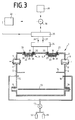
- FIG. 1 shows a sputtering system 1 which has a vacuum chamber 2, in which there are two magnetrons 3, 4.
- a vacuum chamber 2 in which there are two magnetrons 3, 4.
- upper openings 7, 8 and lower openings 9, 10 are provided, wherein in the upper openings 7, 8 vacuum pumps 11, 12 are located, while the lower Openings 9, 10 for the passage of a substrate 13, for example one Glass plate, serve through the vacuum chamber 2.
- an aperture 14 which extends from the side walls 5, 6 protrudes into the interior of the vacuum chamber 2.
- gas supply lines 15, 16 which are connected via a valve 17 with gas containers 18, 19 Connect.
- the magnetrons 3, 4 each have a cathode trough 20, 21 on their Bottom is provided with a target 22, 23. Located in the cathode tubs 20, 21 three permanent magnets 24, 25, 26 and 27, 28, 29, each with a common Yoke 30, 31 are connected.
- the cathode wells 20, 21 are in the top of the vacuum chamber via seals 32, 33 2 fitted. Both cathode wells 20, 21 are with an electrical Filter 34 connected to a medium frequency generator 35.
- this medium frequency generator 35 is not a fixed frequency oscillator or tunable oscillator, but a freely oscillating oscillator whose Frequency always matches the resonance frequency of the network connected to it.
- this cantilever chair can consist of four IGBT modules H inverter circuit exist on the network and the Plasma impedance is working. The inverter circuit is fed via a DC link in the medium frequency generator 35. This is potential-free.
- a Control electronics determined via current and voltage measurement in the output of the Inverter controls the resonant frequency of the oscillatory output the IGBT modules with this.
- the type of inverter circuit as well as that resonant control is known in medium frequency supplies (generator from Wilsontinger or the company EMA-Indutec).
- the network is made up of a medium frequency generator 35 Resonant circuit, an output transformer and outside of the generator from supply lines 36, 37, the capacitance and inductance of the filter 34 and the plasma impedance together.
- the network has the property, the stability of the process by suppressing current transients. Furthermore, with the Network the impedance value at which power matching is present can be varied what can contribute to the stabilization of the working point.
- the AC resistance is shown under plasma impedance of the plasma between the two magnetrons 3, 4 understood. If there were only one magnetron, the plasma impedance would be between them Magnetron and the substrate or another location to which the second polarity of the alternating current is connected. Because the total impedance with which the medium frequency generator 35 is loaded until the plasma impedance is constant the resonance frequency and thus the frequency with which the medium frequency generator 35 vibrates, determined by the plasma impedance. The respective actual frequency of the medium frequency generator 35 thus corresponds to the resonance frequency of the whole Circle and is therefore a function of plasma impedance. The actual frequency will a comparator 38 supplied, which also a target frequency from a target frequency generator 39 is supplied. The target frequency thus corresponds to a control technology Reference variable.
- the difference between the actual frequency and setpoint value is fed to a controller 40, which forms a control signal for the valve 17 from this difference.
- the controller 40 it can be a PI, a PID or a software fuzzy controller with a customized one Act control characteristic.
- the frequency of the cantilever changes Medium frequency generator 35 due to a change in the plasma impedance a difference between the current actual value and the setpoint from the setpoint generator and given to the controller 40. This then generates a control signal which counteracts the frequency difference, i. H. the gas inflow and thus the plasma impedance is changed in such a way that the Set target frequency.
- the medium frequency generator 35 basically oscillates and always at the resonance frequency the output from the resonant circuit, network and plasma impedance. Since all Elements in the resonant circuit and network are fixed, the resonance frequency only depends on the plasma impedance. The plasma impedance is regulated and not the frequency. The frequency is only an indirect actual value for the impedance, d. H. one changes via the manipulated variables power, current, voltage and / or gas flow the impedance, the actual value of the resonance frequency also changes.
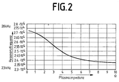
- the plasma resistance is relatively low at a resonance frequency of 2.75 ⁇ 10 4 Hz and relatively high at a resonance frequency of 2.3 ⁇ 10 4 Hz.
- the plasma impedance In order to keep the resonance frequency constant at around 2.5 ⁇ 10 4 Hz, the plasma impedance must be kept at around 4 ⁇ . If the plasma impedance changes, the regulation of the gas flow brings the plasma impedance back to its old value.
- the inflow is not of the process or reactive gas is regulated, but the electrical power of the Medium frequency generator.
- the plasma impedance is not only due to the gas inflow dependent, but also on other variables such as current, voltage and Power, a magnetic field passing through the plasma, a radiation irradiating the plasma UV radiation, the gas composition or the enrichment of the target surface with reactive gas components.
- the principle of the control according to the exemplary embodiment according to FIG. 3 is the same as in the embodiment of FIG. 1.
- the resonance frequency deviates from its Desired value, the electrical power supplied to the magnetrons 3, 4 becomes as long increases or decreases until the setpoint of the resonance frequency is reached Has.
- one process variable each - The gas inflow or electrical power - regulated.
- the invention can also can be realized with only one cathode.
- the plasma path then does not form between the two cathodes, but between the cathode and an anode.
- the anode can be through the vacuum chamber 2 or through one in the vacuum chamber 2 suspended insulated electrodes are formed.
- the working point to be set depends on the demands placed on the layer that is deposited on the substrate 13.
Landscapes
- Physics & Mathematics (AREA)
- Engineering & Computer Science (AREA)
- Plasma & Fusion (AREA)
- Chemical & Material Sciences (AREA)
- Analytical Chemistry (AREA)
- Plasma Technology (AREA)
- Physical Vapour Deposition (AREA)
- Drying Of Semiconductors (AREA)
- Physical Or Chemical Processes And Apparatus (AREA)
Applications Claiming Priority (2)
| Application Number | Priority Date | Filing Date | Title |
|---|---|---|---|
| DE10154229 | 2001-11-07 | ||
| DE10154229A DE10154229B4 (de) | 2001-11-07 | 2001-11-07 | Einrichtung für die Regelung einer Plasmaimpedanz |
Publications (2)
| Publication Number | Publication Date |
|---|---|
| EP1310979A2 true EP1310979A2 (fr) | 2003-05-14 |
| EP1310979A3 EP1310979A3 (fr) | 2006-03-29 |
Family
ID=7704642
Family Applications (1)
| Application Number | Title | Priority Date | Filing Date |
|---|---|---|---|
| EP02022826A Withdrawn EP1310979A3 (fr) | 2001-11-07 | 2002-10-12 | Dispositif de contrôle de l'impédance d'un plasma |
Country Status (4)
| Country | Link |
|---|---|
| US (1) | US6860973B2 (fr) |
| EP (1) | EP1310979A3 (fr) |
| JP (1) | JP2003234200A (fr) |
| DE (1) | DE10154229B4 (fr) |
Cited By (1)
| Publication number | Priority date | Publication date | Assignee | Title |
|---|---|---|---|---|
| WO2007147582A1 (fr) * | 2006-06-20 | 2007-12-27 | Fraunhofer-Gesellschaft zur Förderung der angewandten Forschung e.V. | Procédé de régulation d'un processus de pulvérisation magnétron réactive à impulsions haute puissance et dispositif correspondant |
Families Citing this family (17)
| Publication number | Priority date | Publication date | Assignee | Title |
|---|---|---|---|---|
| DE10154229B4 (de) | 2001-11-07 | 2004-08-05 | Applied Films Gmbh & Co. Kg | Einrichtung für die Regelung einer Plasmaimpedanz |
| JP2005063760A (ja) * | 2003-08-08 | 2005-03-10 | Sekisui Chem Co Ltd | プラズマ処理方法および処理装置 |
| WO2005015963A1 (fr) * | 2003-08-08 | 2005-02-17 | Sekisui Chemical Co., Ltd. | Procede et appareil de traitement au plasma |
| US7244344B2 (en) * | 2005-02-03 | 2007-07-17 | Applied Materials, Inc. | Physical vapor deposition plasma reactor with VHF source power applied through the workpiece |
| US7262606B2 (en) | 2005-03-26 | 2007-08-28 | Huettinger Elektronik Gmbh + Co. Kg | Method of arc detection |
| US20060278524A1 (en) * | 2005-06-14 | 2006-12-14 | Stowell Michael W | System and method for modulating power signals to control sputtering |
| US20070095281A1 (en) * | 2005-11-01 | 2007-05-03 | Stowell Michael W | System and method for power function ramping of microwave liner discharge sources |
| US7842355B2 (en) * | 2005-11-01 | 2010-11-30 | Applied Materials, Inc. | System and method for modulation of power and power related functions of PECVD discharge sources to achieve new film properties |
| JP2007326051A (ja) * | 2006-06-08 | 2007-12-20 | Toshiba Corp | 放電式ガス処理装置およびそのガス処理方法 |
| JP4436350B2 (ja) * | 2006-09-14 | 2010-03-24 | 株式会社アルバック | 薄膜形成方法及び薄膜形成装置 |
| DE102011076404B4 (de) | 2011-05-24 | 2014-06-26 | TRUMPF Hüttinger GmbH + Co. KG | Verfahren zur Impedanzanpassung der Ausgangsimpedanz einer Hochfrequenzleistungsversorgungsanordnung an die Impedanz einer Plasmalast und Hochfrequenzleistungsversorgungsanordnung |
| SG11201912566WA (en) | 2017-06-27 | 2020-01-30 | Canon Anelva Corp | Plasma processing apparatus |
| WO2019004192A1 (fr) | 2017-06-27 | 2019-01-03 | キヤノンアネルバ株式会社 | Dispositif de traitement par plasma |
| JP6595002B2 (ja) | 2017-06-27 | 2019-10-23 | キヤノンアネルバ株式会社 | スパッタリング装置 |
| KR102257134B1 (ko) | 2017-06-27 | 2021-05-26 | 캐논 아네르바 가부시키가이샤 | 플라스마 처리 장치 |
| SG11202009122YA (en) * | 2018-06-26 | 2020-10-29 | Canon Anelva Corp | Plasma processing apparatus, plasma processing method, program, and memory medium |
| CN117004917B (zh) * | 2023-08-14 | 2025-08-15 | 天津吉兆源科技有限公司 | 一种均匀性调节装置及磁控溅射真空镀膜机 |
Family Cites Families (16)
| Publication number | Priority date | Publication date | Assignee | Title |
|---|---|---|---|---|
| US4500408A (en) | 1983-07-19 | 1985-02-19 | Varian Associates, Inc. | Apparatus for and method of controlling sputter coating |
| CA1242989A (fr) * | 1983-07-19 | 1988-10-11 | Donald R. Boys | Appareil et methode de controle pour la pulverisation cathodique |
| JPS6180858A (ja) * | 1984-09-28 | 1986-04-24 | Hitachi Ltd | パワ−mosfet |
| JPH0673319B2 (ja) * | 1987-01-26 | 1994-09-14 | 三菱電機株式会社 | プラズマ装置 |
| DE4106770C2 (de) | 1991-03-04 | 1996-10-17 | Leybold Ag | Verrichtung zum reaktiven Beschichten eines Substrats |
| DE59207306D1 (de) | 1991-04-12 | 1996-11-14 | Balzers Hochvakuum | Verfahren und Anlage zur Beschichtung mindestens eines Gegenstandes |
| JP3251087B2 (ja) * | 1993-02-16 | 2002-01-28 | 東京エレクトロン株式会社 | プラズマ処理装置 |
| JPH0772307A (ja) * | 1993-09-03 | 1995-03-17 | Canon Inc | 薄膜形成方法及び装置 |
| DE19537212A1 (de) | 1994-10-06 | 1996-04-11 | Leybold Ag | Vorrichtung zum Beschichten von Substraten im Vakuum |
| JP2884056B2 (ja) * | 1995-12-07 | 1999-04-19 | パール工業株式会社 | 放電プラズマ発生用高周波電源装置及び半導体製造装置 |
| DE19610012B4 (de) * | 1996-03-14 | 2005-02-10 | Unaxis Deutschland Holding Gmbh | Verfahren zur Stabilisierung eines Arbeitspunkts beim reaktiven Zerstäuben in einer Sauerstoff enthaltenden Atmosphäre |
| JPH1183907A (ja) * | 1997-09-03 | 1999-03-26 | Mitsubishi Electric Corp | 高周波電流の測定方法 |
| JP3296425B2 (ja) * | 1999-03-10 | 2002-07-02 | サンケン電気株式会社 | 電力変換装置 |
| JP3959200B2 (ja) * | 1999-03-19 | 2007-08-15 | 株式会社東芝 | 半導体装置の製造装置 |
| WO2001005020A1 (fr) * | 1999-07-13 | 2001-01-18 | Tokyo Electron Limited | Source d"energie haute frequence destinee a generer du plasma a couplage par induction |
| DE10154229B4 (de) | 2001-11-07 | 2004-08-05 | Applied Films Gmbh & Co. Kg | Einrichtung für die Regelung einer Plasmaimpedanz |
-
2001
- 2001-11-07 DE DE10154229A patent/DE10154229B4/de not_active Expired - Fee Related
-
2002
- 2002-10-12 EP EP02022826A patent/EP1310979A3/fr not_active Withdrawn
- 2002-11-01 JP JP2002319971A patent/JP2003234200A/ja active Pending
- 2002-11-04 US US10/287,452 patent/US6860973B2/en not_active Expired - Fee Related
Cited By (1)
| Publication number | Priority date | Publication date | Assignee | Title |
|---|---|---|---|---|
| WO2007147582A1 (fr) * | 2006-06-20 | 2007-12-27 | Fraunhofer-Gesellschaft zur Förderung der angewandten Forschung e.V. | Procédé de régulation d'un processus de pulvérisation magnétron réactive à impulsions haute puissance et dispositif correspondant |
Also Published As
| Publication number | Publication date |
|---|---|
| DE10154229A1 (de) | 2003-05-15 |
| EP1310979A3 (fr) | 2006-03-29 |
| US6860973B2 (en) | 2005-03-01 |
| DE10154229B4 (de) | 2004-08-05 |
| JP2003234200A (ja) | 2003-08-22 |
| US20030087044A1 (en) | 2003-05-08 |
Similar Documents
| Publication | Publication Date | Title |
|---|---|---|
| DE10154229B4 (de) | Einrichtung für die Regelung einer Plasmaimpedanz | |
| DE19610012B4 (de) | Verfahren zur Stabilisierung eines Arbeitspunkts beim reaktiven Zerstäuben in einer Sauerstoff enthaltenden Atmosphäre | |
| EP2140476B1 (fr) | Source d'evaporation sous vide a arc, ainsi qu'une chambre d'evaporation a arc comprenant une source d'evaporation sous vide a arc | |
| EP1869690B2 (fr) | Procédé d'utilisation d'une source d'arc pulsée | |
| EP0508359B1 (fr) | Procédé et dispositif pour le revêtement d'au moins un objet | |
| DE69914435T2 (de) | Abstimmbare und anpassbare Resonator-Spulenanordnung für Ionenimplantation-Linearbeschleuniger | |
| EP0347567A2 (fr) | Dispositif de revêtement d'un diélectrique sur un substrat | |
| WO2006099759A2 (fr) | Generateur de plasma sous vide | |
| DE102018204587A1 (de) | Verfahren zur Zündung eines Plasmas in einer Plasmakammer und Zündschaltung | |
| EP0282835B1 (fr) | Procédé et dispositif de contrôle du dépôt réactif de couches sur des substrats au moyen de cathodes magnétron | |
| CH689767A5 (de) | Verfahren zur Werkstueckbehandlung in einer Vakuumatmosphaere und Vakuumbehandlungsanlage. | |
| EP0767483B1 (fr) | Dispositif de revêtement de substrats dans le vide | |
| WO2000025344A1 (fr) | Procede pour surveiller une decharge de tension alternative au niveau d'une double electrode | |
| EP3289113A1 (fr) | Procédé de fabrication de substrats revêtus | |
| EP0666335B1 (fr) | Méthode de conduite d'opération d'un évaporateur à arc sous vide et sa source de courant | |
| EP0710429B1 (fr) | Procede permettant d'adapter le generateur dans des processus bipolaires de decharge par effluves basse pression | |
| DE4138793C2 (de) | Verfahren und Vorrichtung zum Beschichten eines Substrats, insbesondere mit elektrisch nichtleitenden Schichten | |
| DE3426145A1 (de) | Verfahren zur regelung der plasmaparameter in vakuumbeschichtungseinrichtungen mit bogenentladungen | |
| CH691686A5 (de) | Vakuumbehandlungskammer. | |
| EP0880795B1 (fr) | Procede pour commander la repartition energetique dans des processus bipolaires a decharge lumineuse basse pression | |
| DE102009017888B4 (de) | Verfahren und Vorrichtung zum Steuern einer Plasmadichteverteilung in einem Vakuumprozess | |
| DE102009008290A1 (de) | Verfahren und Vorrichtung zum Beschichten eines Substrats unter Verwendung eines reaktiven Sputterprozesses | |
| DE10234858A1 (de) | Einrichtung zur Erzeugung einer Magnetron-Entladung | |
| DE3801309C2 (fr) | ||
| DE102004025679A1 (de) | Vorrichtung und Verfahren zum Verändern der Impedanz einer Hochfrequenz-Plasmaentladung |
Legal Events
| Date | Code | Title | Description |
|---|---|---|---|
| PUAI | Public reference made under article 153(3) epc to a published international application that has entered the european phase |
Free format text: ORIGINAL CODE: 0009012 |
|
| AK | Designated contracting states |
Designated state(s): AT BE BG CH CY CZ DE DK EE ES FI FR GB GR IE IT LI LU MC NL PT SE SK TR |
|
| AX | Request for extension of the european patent |
Extension state: AL LT LV MK RO SI |
|
| PUAL | Search report despatched |
Free format text: ORIGINAL CODE: 0009013 |
|
| AK | Designated contracting states |
Kind code of ref document: A3 Designated state(s): AT BE BG CH CY CZ DE DK EE ES FI FR GB GR IE IT LI LU MC NL PT SE SK TR |
|
| AX | Request for extension of the european patent |
Extension state: AL LT LV MK RO SI |
|
| 17P | Request for examination filed |
Effective date: 20060818 |
|
| RAP1 | Party data changed (applicant data changed or rights of an application transferred) |
Owner name: APPLIED MATERIALS GMBH & CO. KG |
|
| AKX | Designation fees paid |
Designated state(s): AT BE BG CH CY CZ DE DK EE ES FI FR GB GR IE IT LI LU MC NL PT SE SK TR |
|
| 17Q | First examination report despatched |
Effective date: 20081114 |
|
| STAA | Information on the status of an ep patent application or granted ep patent |
Free format text: STATUS: THE APPLICATION IS DEEMED TO BE WITHDRAWN |
|
| 18D | Application deemed to be withdrawn |
Effective date: 20100504 |