EP1314302B1 - Ensemble mains libres pour poste de radiotelephone mobile - Google Patents
Ensemble mains libres pour poste de radiotelephone mobile Download PDFInfo
- Publication number
- EP1314302B1 EP1314302B1 EP01963196A EP01963196A EP1314302B1 EP 1314302 B1 EP1314302 B1 EP 1314302B1 EP 01963196 A EP01963196 A EP 01963196A EP 01963196 A EP01963196 A EP 01963196A EP 1314302 B1 EP1314302 B1 EP 1314302B1
- Authority
- EP
- European Patent Office
- Prior art keywords
- hands
- free kit
- transmitter
- earpiece
- receiver
- Prior art date
- Legal status (The legal status is an assumption and is not a legal conclusion. Google has not performed a legal analysis and makes no representation as to the accuracy of the status listed.)
- Expired - Lifetime
Links
Images




Classifications
-
- H—ELECTRICITY
- H04—ELECTRIC COMMUNICATION TECHNIQUE
- H04M—TELEPHONIC COMMUNICATION
- H04M1/00—Substation equipment, e.g. for use by subscribers
- H04M1/60—Substation equipment, e.g. for use by subscribers including speech amplifiers
- H04M1/6033—Substation equipment, e.g. for use by subscribers including speech amplifiers for providing handsfree use or a loudspeaker mode in telephone sets
- H04M1/6041—Portable telephones adapted for handsfree use
- H04M1/6058—Portable telephones adapted for handsfree use involving the use of a headset accessory device connected to the portable telephone
- H04M1/6066—Portable telephones adapted for handsfree use involving the use of a headset accessory device connected to the portable telephone including a wireless connection
-
- H—ELECTRICITY
- H04—ELECTRIC COMMUNICATION TECHNIQUE
- H04M—TELEPHONIC COMMUNICATION
- H04M1/00—Substation equipment, e.g. for use by subscribers
- H04M1/02—Constructional features of telephone sets
- H04M1/04—Supports for telephone transmitters or receivers
- H04M1/05—Supports for telephone transmitters or receivers specially adapted for use on head, throat or breast
-
- H—ELECTRICITY
- H04—ELECTRIC COMMUNICATION TECHNIQUE
- H04W—WIRELESS COMMUNICATION NETWORKS
- H04W52/00—Power management, e.g. Transmission Power Control [TPC] or power classes
- H04W52/02—Power saving arrangements
- H04W52/0209—Power saving arrangements in terminal devices
- H04W52/0261—Power saving arrangements in terminal devices managing power supply demand, e.g. depending on battery level
- H04W52/0274—Power saving arrangements in terminal devices managing power supply demand, e.g. depending on battery level by switching on or off the equipment or parts thereof
-
- Y—GENERAL TAGGING OF NEW TECHNOLOGICAL DEVELOPMENTS; GENERAL TAGGING OF CROSS-SECTIONAL TECHNOLOGIES SPANNING OVER SEVERAL SECTIONS OF THE IPC; TECHNICAL SUBJECTS COVERED BY FORMER USPC CROSS-REFERENCE ART COLLECTIONS [XRACs] AND DIGESTS
- Y02—TECHNOLOGIES OR APPLICATIONS FOR MITIGATION OR ADAPTATION AGAINST CLIMATE CHANGE
- Y02D—CLIMATE CHANGE MITIGATION TECHNOLOGIES IN INFORMATION AND COMMUNICATION TECHNOLOGIES [ICT], I.E. INFORMATION AND COMMUNICATION TECHNOLOGIES AIMING AT THE REDUCTION OF THEIR OWN ENERGY USE
- Y02D30/00—Reducing energy consumption in communication networks
- Y02D30/70—Reducing energy consumption in communication networks in wireless communication networks
Definitions
- the present invention relates to a hands-free kit for a mobile radio-telephone handset.
- a number of hands-free kits have been devised which connect an earpiece and microphone to a handset via wires, thereby allowing the handset to be located a safe distance from the user's head.
- the connecting wires of such kits act as a conduit, channelling microwave radiation from the handset to the user's head.
- JP11308326 describes a portable telephone communications system.
- a hands-free kit for a mobile radio-telephone handset according to claim 1.
- audio signals may be relayed from the handset to the earpiece with the reduced likelihood of the earpiece becoming dislodged as the user moves his head.
- the transmitter may communicate with the handset via a wired or wireless connection, such as a radio frequency connection provided by Bluetooth ® or Bluetooth ® -type communications devices.
- the receiver may be located at the distal end of a portion of the earpiece which, in use, projects forwards from the user's ear.
- the receiver comprises a plurality of photosensitive devices arranged to receive infra-red signals from different respective directions including the direction of the transmitter.
- the earpiece may comprise means, provided on a forwards projecting portion of the earpiece, for reflecting audio signals from at least the direction of the transmitter towards the receiver.
- the attaching means may comprise a clip or pin for attaching the transmitter to the breast pocket or the lapel of a jacket or to a neck-tie.
- the hands-free kit also comprises a microphone for connecting to the handset, the microphone preferably comprising part of an integrated unit also comprising the transmitter.
- the microphone preferably also communicates with the handset via the same wireless connection.
- the transmitter may be powered from the power supply of the handset or may comprise its own re-chargeable power supply.
- the earpiece preferably comprises a re-chargeable power supply, which may be arranged to be re-charged via a mains adapter or by plugging the earpiece, either directly or via an adaptor, into the cigarette lighter socket of a vehicle.
- the kit comprises a holder for the earpiece and the transmitter via which respective re-chargeable power supplies of the two devices may be charged.
- the holder may be arranged to charge the earpiece and transmitter either directly from an external supply or via its own re-chargeable supply, to enable the earpiece and transmitter to be charged in the absence of said external supply.
- the power supply of the transmitter will be exhausted sooner than that of the earpiece.
- the holder is preferably arranged prevent the earpiece from being charged independently of the transmitter.
- an electrically conductive part of the transmitter may be arranged to bridge a pair of contacts of the holder to complete a charging circuit for the earpiece.
- the holder may also or otherwise be arranged to prevent the transmitter from being charged independently of the earpiece.
- the holder may be provided with means for visibly indicating its state of charge and/or the state of charge of the transmitter and/or of the earpiece.
- the transmitter and the earpiece preferably comprise independent means for visibly indicating their respective states of charge, the holder preferably comprising a lidded case having a portion which is at least partially transparent and through which the charge indicating means of the transmitter and earpiece may be viewed.
- the indicating means preferably comprise respective lights, e.g. light emitting diodes, which may, for example, be constantly illuminated, extinguished or illuminated intermittently to indicate different states of charge.
- lights e.g. light emitting diodes, which may, for example, be constantly illuminated, extinguished or illuminated intermittently to indicate different states of charge.
- the transmitter and earpiece each comprise a respective light which is illuminated intermittently when the device is operating (to indicate that the device is charged), is constantly illuminated when the device is being charged and is extinguished when the device has exhausted its power supply.
- the earpiece emits an audible warning signal to indicate when the power supply of the transmitter and/or the earpiece is nearing exhaustion.
- the earpiece emits a periodic audible signal, with the frequency of the emitted signal increasing as the power supply of the earpiece and/or the transmitter is exhausted.
- the earpiece may emit an audible signal every 5 minutes when there is between 5 and 30 minutes of charge remaining in the transmitter and/or the receiver, every 1 minute when between 30 seconds and 5 minutes of charge remains and every second when less that 1 second of charge remains.
- Signals transmitted from the transmitter to the receiver may be encrypted.
- the transmitter and receiver may be arranged to respectively encode and decode signals using a unique encryption algorithm.
- the transmitter and receiver may be arranged to respectively encode and decode signals using one of a plurality of encryption algorithms chosen on a random basis, the number of possible encryption algorithms being sufficient to ensure an acceptably low likelihood of the same encryption algorithm being used by two transmitter/receiver pairs in the same vicinity.
- the transmitter and receiver may be pre-programmed with an appropriate encryption key.
- the encryption key is preferably transmitted from the transmitter to the receiver, having preferably been generated by the transmitter.
- the encryption algorithm may, for example, be derived from the phone number or other identification code of the handset with which the hands-free kit is to be used, or a new key, chosen at random, may be transmitted to the receiver on a periodic basis, for example each time the transmitter is charged.
- the transmitter may also or otherwise be arranged to transmit an identification signal to identify itself to the earpiece.
- the identification signal may be unique or may be chosen at random from one of a plurality of possible signals, the number of possible signals being sufficient to ensure an acceptably low likelihood of the same identification signal being used by two transmitter/receiver pairs in the same vicinity.
- the transmitter and receiver may be pre-programmed to operate using a particular identification signal.
- the identification signal to be used is preferably communicated from the transmitter to the receiver, having preferably been generated internally by the transmitter.
- the signal may, for example, be derived from the phone number or other identification code of the handset with which the hands-free kit is to be used, or a new signal, chosen at random, may be communicated to the earpiece on a periodic basis, for example each time the transmitter is charged.
- the earpiece may be arranged to respond to an invalid identification signal by emitting an audible warning signal.
- the transmitter is preferably arranged to periodically transmit said identification signal.
- the earpiece may be arranged to provide an audible alarm signal if a valid identification signal is not received over a pre-determined period of time.
- the earpiece is arranged to operate for periods in a standby mode, wherein one or more functions of the earpiece are disabled to conserve power, the earpiece preferably being arranged to enter the standby mode in the absence of a received signal or if a valid identification signal is not received.
- the or each disabled function is preferably restored in response to a received signal, preferably only if that signal comprises a valid identification signal.
- Entry into the standby mode may be immediate or may be delayed in one or more of the above circumstances.
- the earpiece may be arranged to enter a standby mode in the absence of a received signal or if a valid identification signal (such as one transmitted periodically by the transmitter) is not received over a pre-determined period of time. Preferably, the earpiece will then return to full functionality only on receiving a valid identification signal.
- a valid identification signal such as one transmitted periodically by the transmitter
- the transmitter is preferably arranged to operate for periods in a standby mode, wherein one or more functions of the transmitter are disabled to conserve power, in the absence of an audio signal from the handset.
- the hands-free kit may be arranged to transmit infra-red light of a constantly high level of intensity, such that the receiver is certain to receive the infra-red light emitted by the transmitter over a range of orientations of the user's head and over a range of ambient light levels.
- the hands-free kit therefore preferably comprises a second infra-red receiver, located adjacent the transmitter, and means for varying the intensity of the infra-red light emitted by the transmitter according the amount of infra-red light received by the second receiver.
- the earpiece preferably comprises means for reflecting a portion of the infra-red light emitted by the transmitter back towards the second receiver.
- the reflecting means preferably comprise a part-spherical, multi-faceted arrangement of mirrors, which is preferably located at the distal end of the forward projecting portion of the earpiece.
- Each facet preferably comprises a respective concave parabolic mirror.
- An alternative means for optimising the amount of light received by the earpiece from the transmitter in accordance with the present invention is to provide a set-up mode, wherein the transmitter emits a light signal of substantially constant amplitude and the earpiece emits a periodic audible signal, whose periodicity varies in accordance with the amount of light received from the transmitter as the position of the transmitter is adjusted by a user, for example by increasing in frequency with the amount of light received from the transmitter.
- the earpiece comprises a tail portion for hooking around the ear of the wearer, a portion which extends over and forwards from the user's ear and a portion which extends rearwards from the front of the device to position a microphone over the external auditory canal of the wearer.
- an elastomeric grip is fitted to the tail portion of the earpiece, which is preferably replaceable to allow the shape of the device to be readily modified to fit different sized and shaped ears and the device to be personalised to the wearer's taste by replacing the grip with one of a different colour.
- the front of the earpiece is provided with a window, behind which a pair of photosensitive devices are arranged to receive infra-red signals from different respective directions.
- the tail portion of the earpiece houses electronic circuitry and a rechargeable power supply.
- the microphone is rotatable about the axis of the rearwardly projecting portion, to enable the earpiece to be configured for fitting to either the left or the right ear of the wearer.
- abutting parts of the rearwardly projecting portion and a housing of the microphone ensure that the microphone can only be rotated through 180 degrees between its left and right handed orientations.
- a person 2 is shown wearing a hands-free kit in accordance with the present invention.
- the hands-free kit comprises an earpiece 4 and a transmitter unit 6, clipped to the breast pocket 8 of the person's jacket, for relaying audio signals from a mobile radio telephone-handset (not shown), via an infra-red transmitter of the unit, to an infra-red receiver 10 of the earpiece 4.
- the transmitter unit 6 also comprises a microphone, with audio signals being transmitted from the handset to the infra-red transmitter of the unit and from the microphone to the handset, via either a wired or a wireless link, so that the handset may be located a safe distance from the user's head.
- the earpiece 4 is arranged to become activated upon receiving an audio signal from the transmitter unit 6, if preceded by a valid identification code, to provide an audible output of the audio signal via a speaker 14 adjacent the user's ear 12.
- the transmitter unit 6 is arranged to periodically retransmit the identity code within an audio stream, the earpiece 4 being arranged entering a standby mode, to conserve power, in the absence of a received signal or where a valid identity code is not received within a period of time.
- the transmitter unit 6 is also arranged to enter a standby mode, to conserve power, in the absence of a signal from the handset.
- the transmitter unit 6 and earpiece 4 are powered by respective re-chargeable supplies and are re-charged by fitting the two parts to a holder, such as that described in detail below. As the power supply of the earpiece 4 and/or the transmitter unit 6 is nearing exhaustion, the earpiece 4 periodically emits an audible warning signal whose frequency increases, the nearer the power supply of either unit comes to being fully discharged.
- a new identification code is generated at random by the transmitter unit 6 and communicated to the earpiece 4, by which the earpiece 4 can then identify audio signals originating from that transmitter 6.
- the earpiece 4 is also arranged, for example by pre-programming the earpiece or by programming the earpiece in-situ, to generate an audible output of received audio signals preceded by at least one other identification code, such as may be assigned to an infra-red transmitter installed in a public facility or retail outlet, the earpiece 4 preferably being arranged to give precedence to signals identified as having been received from the transmitter unit 6.
- the infra-red receiver 10 of the earpiece 4 comprises a pair of photosensitive devices, one of which is directed downwards towards the transmitter unit 6, the other being directed upwards to receive signals from said other sources.
- the transmitter unit 6 is also provided with an infra-red receiver (not shown), adjacent the infra-red transmitter thereof, for adjusting the level of intensity of infra-red signals emitted from the unit, according to ambient light levels.
- a first earpiece 4 is shown in detail in Figures 4 to 6 .
- Two part-cylindrical halves 16,18 of a clip 20 are hingedly joined together along the top of the earpiece and are each lined with a cushioning material 22.
- a telescopic rod 24 extends forwards from the clip 20 and is provided at its distal end with an infra-red receiver 26. A portion of the rod, also at its distal end, is touch-sensitive for activating and deactivating the electronic circuitry of the earpiece. In its retracted position, the projecting portion of the rod 24 is arranged to fit either directly, or via an adaptor, into the cigarette lighter socket of a vehicle to recharge the power supply of the earpiece via electrical contacts on the exterior of the rod.
- the distal end of the rod 24 may also be provided with a part-spherical mirrored portion (not shown), preferably comprising a plurality of concave parabolic facets, for reflecting a portion of the infra-red light emitted by the transmitter back towards an infra-red receiver located adjacent the transmitter.
- a part-spherical mirrored portion (not shown), preferably comprising a plurality of concave parabolic facets, for reflecting a portion of the infra-red light emitted by the transmitter back towards an infra-red receiver located adjacent the transmitter.
- Means are provided for varying the intensity of light emitted by the transmitter 6 according to the amount of light reflected to ensure that the amount of infra-red light falling upon the receiver 26 of the earpiece 4 remains substantially constant regardless of the orientation of the person's head and thus the distance and/or misalignment between the transmitter 6 and the earpiece receiver 26.
- the infra-red receiver located adjacent the transmitter 6 may also or otherwise be used to adjust the intensity of light emitted by the transmitter according to ambient light levels.
- a speaker 14 and a housing 28 depend on opposite sides of the earpiece, from respective halves 16,18 of the clip 20, the housing 28 accommodating the re-chargeable power supply and electronic circuitry of the earpiece 4.
- the earpiece 4 is fitted to a person's ear 12 as shown in Figures 7 and 8 by first separating the speaker 14 and housing 28 parts of the earpiece to open the clip 20 and then bringing the two parts 14,28 back together, on opposite sides of the person's ear 12 such that the clip 20 becomes attached to the top of the ear 12, with the speaker 14 positioned within the ear, the housing 28 extending behind the ear and the telescopic rod 24 extending forwards from the ear.
- a second earpiece 4 is shown in Figure 9 , and comprises a parabolic concave mirror 30 for reflecting signals from the transmitter to a receiver located adjacent the speaker 14.
- a third earpiece 4 is shown in Figures 10 to 12 and, in an alternative configuration in Figure 13 , the earpiece comprising a tail portion 32 for hooking around the ear of the wearer, a portion 34 which, in use, extends forwards from the wearer's ear and a portion 36 which extends rearwards from the front of the device to support a microphone 38 over the external auditory canal of the wearer.
- An elastomeric grip 40, fitted to the tail portion 32 of the earpiece is replaceable to allow the shape of the device to be readily modified to fit different sized and shaped ears and the device to be personalised to the wearer's taste by replacing the grip 40 with one of a different colour.
- the front of the earpiece is provided with a window 42, behind which a pair of photosensitive devices are arranged to receive infra-red signals from above and below the earpiece respectively.
- the tail portion 32 of the earpiece houses electronic circuitry and a rechargeable power supply.
- the microphone 38 is rotatable about the axis of the rearwardly projecting portion 36, as illustrated in Figure 13 , to enable the earpiece to be configured for fitting either to the left or the right ear of the wearer.
- Abutting parts of the portion 36 and a housing 44 of the microphone ensure that the microphone can only be rotated through 180 degrees between its left and right handed orientations.
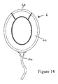
- a preferred transmitter unit 6 is shown in Figures 14 to 16 and comprises a main body 46, within which electronic circuitry and a re-chargeable power supply are housed, the body part 46 being provided at opposite ends with an infra-red emitter 48 and a lead 50 for connecting the transmitter tc a mobile radio-telephone handset.
- a clip 52 having an integral metallic fastening pin 53 is provided at the rear of the body part 46, for respectively clipping or pinning the transmitter unit to an outer garment of user, the clip 52 being detachable from the body part to be replaced by an alternative fastening device if required.
- Figures 17 to 21 show a holder in the form of a case 54, having an internal tray 56 shaped to receive the earpiece and transmitter units of Figures 10 to 16 , as shown in Figure 19 , for charging those devices either directly from an external power supply or via a rechargeable power source of the case.
- the case 54 is provided with a socket 58 for connecting to said external power supply and two pairs of charging pins 60,62 arranged to register with respective pairs of terminals 64,68 formed in the bodies of the earpiece and transmitter units.
- a further pair of electrical contacts 70,72 are arranged to be bridged by the fastening pin 53 of the transmitter unit 6, when that unit is fitted to the case, to complete a circuit for charging the earpiece 4.
- the lid 74 of the case 54 is partially transparent, to provide a view of respective light emitting diodes (not shown) of the earpiece and transmitter units, which are illuminated whilst the devices are being charged.
- the same lights are preferably illuminated intermittently whilst the devices are operating (to provide an indication of whether the devices are charged), and are extinguished when their respective power supplies are exhausted.
- An aperture 76 in the side of the case 54 provides a passageway through which the connecting lead 50 of the transmitter unit 6 may exit the case, to then be routed around a channel 78 formed in the sides of the case and secured in place by locating a connector at the end of the lead within a correspondingly shaped recess 80 formed in the base of the case.
- the wireless, hands-free arrangements thus described provide a much safer and more convenient alternative to existing hand-free arrangements for use with mobile radio-telephone handsets.
Landscapes
- Engineering & Computer Science (AREA)
- Signal Processing (AREA)
- Health & Medical Sciences (AREA)
- Otolaryngology (AREA)
- Computer Networks & Wireless Communication (AREA)
- Telephone Set Structure (AREA)
- Telephone Function (AREA)
- Mobile Radio Communication Systems (AREA)
- Circuits Of Receivers In General (AREA)
Claims (65)
- Kit mains libres pour un combiné radiotéléphonique mobile, le kit comprenant un écouteur (4) et un émetteur infrarouge (6), l'émetteur (6) étant agencé pour relayer des signaux audio du combiné à l'écouteur (4), l'écouteur comprenant un récepteur infrarouge (10) destiné à recevoir des signaux audio de l'émetteur (6), caractérisé en ce que l'émetteur infrarouge (6) comprend des moyens (52, 53) de fixation de l'émetteur infrarouge (6) à l'avant d'un utilisateur, dans la ligne de mire de l'écouteur (4).
- Kit mains libres selon la revendication 1, dans lequel l'émetteur (6) communique avec le combiné via une connexion par câble (50).
- Kit mains libres selon la revendication 1, dans lequel l'émetteur (6) communique avec le combiné via une connexion sans fil.
- Kit mains libres selon l'une quelconque des revendications précédentes, dans lequel le récepteur (10) est situé au niveau de l'extrémité distale d'une portion de l'écouteur (4) qui, en utilisation, fait saillie vers l'avant à partir de l'oreille de l'utilisateur.
- Kit mains libres selon l'une quelconque des revendications précédentes, dans lequel le récepteur (10) comprend une pluralité de dispositifs photosensibles agencés pour recevoir des signaux infrarouges provenant de directions respectives différentes comprenant la direction de l'émetteur (6).
- Kit mains libres selon l'une quelconque des revendications 1 à 4, dans lequel des moyens sont disposés sur une portion en saillie vers l'avant de l'écouteur (4) afin de réfléchir des signaux audio d'au moins la direction de l'émetteur (6) vers le récepteur (10).
- Kit mains libres selon l'une quelconque des revendications précédentes, comprenant un microphone pour une connexion au combiné.
- Kit mains libres selon la revendication 7, dans lequel le microphone fait partie d'une unité intégrée constituant également l'émetteur (6).
- Kit mains libres selon la revendication 7 annexée à la revendication 3, dans lequel le microphone et l'émetteur (6) communiquent chacun avec le combiné via la même connexion sans fil.
- Kit mains libres selon l'une quelconque des revendications précédentes, dans lequel l'émetteur (6) comprend une alimentation rechargeable.
- Kit mains libres selon l'une quelconque des revendications précédentes, dans lequel l'écouteur (4) comprend une alimentation rechargeable.
- Kit mains libres selon la revendication 11 annexée à la revendication 10, dans lequel le kit comprend un support (54) pour l'écouteur (4) et l'émetteur (6) par l'intermédiaire duquel les alimentations rechargeables des deux dispositifs peuvent être chargées.
- Kit mains libres selon la revendication 12, dans lequel le support (54) est agencé pour charger l'écouteur (4) et l'émetteur (6) directement à partir d'une alimentation externe.
- Kit mains libres selon la revendication 12, dans lequel le support (54) est agencé pour charger l'écouteur (4) et l'émetteur (6) directement par le biais de sa propre alimentation rechargeable.
- Kit mains libres selon l'une quelconque des revendications 12 à 14, dans lequel le support (54) est agencé pour empêcher l'écouteur (4) d'être chargé indépendamment de l'émetteur (6).
- Kit mains libres selon l'une quelconque des revendications 12 à 15, dans lequel le support (54) est agencé pour empêcher l'émetteur (6) d'être chargé indépendamment de l'écouteur (4).
- Kit mains libres selon la revendication 14, dans lequel le support (54) est doté de moyens destinés à indiquer de façon visible son état de charge.
- Kit mains libres selon l'une quelconque des revendications 12 à 17, dans lequel le support (54) est doté de moyens destinés à indiquer de façon visible l'état de charge de l'émetteur (6) et/ou de l'écouteur (4).
- Kit mains libres selon la revendication 10 ou la revendication 12, dans lequel l'émetteur (6) est doté de moyens destinés à indiquer de façon visible son état de charge.
- Kit mains libres selon la revendication 11 ou la revendication 12, dans lequel l'écouteur (4) est doté de moyens destinés à indiquer de façon visible son état de charge.
- Kit mains libres selon la revendication 19 ou la revendication 20 annexée à la revendication 12, dans lequel le support (54) comprend un boîtier équipé d'un couvercle comportant une portion (74) au moins partiellement transparente et à travers laquelle les moyens d'indication de charge de l'émetteur (6) et/ou de l'écouteur (4) peuvent être visualisés.
- Kit mains libres selon l'une quelconque des revendications 17 à 21, dans lequel ledit moyen d'indication ou chacun desdits moyens d'indication comprend une lumière respective.
- Kit mains libres selon la revendication 22, dans lequel ladite lumière est constamment allumée, éteinte ou allumée de façon intermittente afin d'indiquer des états de charge différents.
- Kit mains libres selon la revendication 10 ou la revendication 11, dans lequel l'écouteur (4) émet un signal d'alerte sonore pour indiquer lorsque l'alimentation de l'émetteur (6) et/ou de l'écouteur (4) est proche de l'épuisement.
- Kit mains libres selon la revendication 24, dans lequel ledit signal sonore comprend un signal périodique dont la fréquence s'élève à mesure que l'alimentation de l'écouteur (4) et/ou de l'émetteur (6) s'épuise.
- Kit mains libres selon l'une quelconque des revendications précédentes, dans lequel les signaux transmis par l'émetteur (6) au récepteur (10) sont chiffrés.
- Kit mains libres selon la revendication 26, dans lequel l'émetteur (6) et le récepteur (10) sont agencés pour coder et décoder respectivement des signaux en utilisant un algorithme de chiffrement unique.
- Kit mains libres selon la revendication 26, dans lequel l'émetteur (6) et le récepteur (10) sont agencés pour coder et décoder respectivement des signaux en utilisant l'un d'une pluralité d'algorithmes de chiffrement choisis de façon aléatoire.
- Kit mains libres selon l'une quelconque des revendications 26 à 28, dans lequel l'émetteur (6) et le récepteur (10) sont préprogrammés avec une clé de chiffrement appropriée.
- Kit mains libres selon l'une quelconque des revendications 26 à 28, dans lequel la clé de chiffrement est transmise par l'émetteur (6) au récepteur (10).
- Kit mains libres selon la revendication 30, dans lequel la clé de chiffrement est générée par l'émetteur (6).
- Kit mains libres selon la revendication 31, dans lequel la clé de chiffrement est dérivée du numéro de téléphone ou d'un autre code d'identification du combiné avec lequel le kit mains libres doit être utilisé.
- Kit mains libres selon la revendication 31, dans lequel la clé de chiffrement est choisie au hasard.
- Kit mains libres selon la revendication 33, dans lequel une nouvelle clé, choisie au hasard, est transmise au récepteur (10) de façon périodique.
- Kit mains libres selon l'une quelconque des revendications précédentes, dans lequel l'émetteur (6) est agencé pour transmettre un signal d'identification afin de s'identifier à l'écouteur (4).
- Kit mains libres selon la revendication 35, dans lequel le signal d'identification est unique.
- Kit mains libres selon la revendication 35, dans lequel le signal d'identification est choisi au hasard dans une pluralité de signaux possibles.
- Kit mains libres selon l'une quelconque des revendications 35 à 37, dans lequel l'émetteur (6) et le récepteur (10) sont préprogrammés pour fonctionner en utilisant un signal d'identification particulier.
- Kit mains libres selon les revendications 35 à 37, dans lequel le signal d'identification est communiqué par l'émetteur (6) au récepteur (10).
- Kit mains libres selon la revendication 39, dans lequel le signal d'identification est généré par l'émetteur (6).
- L Kit mains libres selon la revendication 40, dans lequel le signal d'identification est dérivé du numéro de téléphone ou d'un autre code d'identification du combiné avec lequel le kit mains libres doit être utilisé.
- Kit mains libres selon la revendication 40, dans lequel le signal d'identification est choisi au hasard.
- Kit mains libres selon la revendication 42, dans lequel un nouveau signal, choisi au hasard, est communiqué à l'écouteur (4) de façon périodique.
- Kit mains libres selon l'une quelconque des revendications 35 à 43, dans lequel l'écouteur (4) est agencé pour répondre à un signal d'identification invalide en émettant un signal d'alerte sonore.
- Kit mains libres selon l'une quelconque des revendications 35 à 44, dans lequel l'émetteur (6) est agencé pour émettre périodiquement ledit signal d'identification dans un flux de signaux audio.
- Kit mains libres selon la revendication 45, dans lequel l'écouteur (4) est agencé pour fournir un signal d'alerte audible si un signal d'identification valide n'est pas reçu sur une période prédéterminée.
- Kit mains libres selon l'une quelconque des revendications précédentes, dans lequel l'écouteur (4) est agencé pour fonctionner pendant des périodes en mode veille, dans lequel une ou plusieurs fonctions de l'écouteur (4) sont désactivées pour économiser de l'énergie.
- Kit mains libres selon la revendication 47, dans lequel l'écouteur (4) est agencé pour entrer en mode veille en l'absence d'un signal reçu.
- Kit mains libres selon la revendication 47 annexée à l'une quelconque des revendications 35 à 46, dans lequel l'écouteur (4) est agencé pour entrer en mode veille si un signal d'identification valide n'est pas reçu.
- Kit mains libres selon l'une quelconque des revendications 47 à 49, dans lequel la fonction désactivée ou chacune des fonctions désactivées est restaurée en réponse à un signal reçu.
- Kit mains libres selon la revendication 50, dans lequel la fonction désactivée ou chacune des fonctions désactivées est restaurée uniquement si le signal reçu comprend un signal d'identification valide.
- Kit mains libres selon l'une quelconque des revendications 47 à 51, dans lequel l'entrée en mode veille est immédiate.
- Kit mains libres selon l'une quelconque des revendications 47 à 51, dans lequel l'entrée en mode veille est différée.
- Kit mains libres selon l'une quelconque des revendications précédentes, dans lequel l'émetteur (6) est agencé pour fonctionner pendant certaines périodes en mode veille, dans lequel une ou plusieurs fonctions de l'émetteur (6) sont désactivées pour économiser de l'énergie, en l'absence d'un signal audio provenant du combiné.
- Kit mains libres selon l'une quelconque des revendications précédentes, comprenant un second récepteur infrarouge, situé de façon adjacente à l'émetteur (6), et des moyens destinés à faire varier l'intensité de la lumière infrarouge émise par l'émetteur (6) selon la quantité de lumière infrarouge reçue par le second récepteur.
- Kit mains libres selon l'une quelconque des revendications précédentes, agencé pour disposer d'un mode de configuration, dans lequel l'émetteur (6) émet un signal lumineux d'une amplitude sensiblement constante et l'écouteur (4) émet un signal sonore périodique dont la périodicité varie en fonction de la quantité de lumière reçue de la part de l'émetteur (6) lorsque la position de l'émetteur (6) est ajustée par un utilisateur.
- Kit mains libres selon la revendication 1, dans lequel l'écouteur (4) comprend une portion de fuite destinée à être accrochée autour de l'oreille du porteur, une portion qui s'étend au-dessus de l'oreille du porteur et vers l'avant et une portion qui s'étend vers l'arrière depuis l'avant de l'écouteur (4) pour positionner un microphone sur le conduit auditif externe du porteur.
- Kit mains libres selon la revendication 57, dans lequel l'écouteur (4) dispose d'un élément de préhension élastomère ajusté à la portion de fuite de l'écouteur (4).
- Kit mains libres selon la revendication 58, dans lequel ledit élément de préhension élastomère est remplaçable.
- Kit mains libres selon la revendication 57, dans lequel l'avant de l'écouteur (4) est doté d'une fenêtre, derrière laquelle une paire de dispositifs photosensibles est agencée pour recevoir des signaux infrarouges provenant de directions respectives différentes.
- Kit mains libres selon la revendication 57, dans lequel la portion de fuite de l'écouteur (4) loge des circuits électroniques et une alimentation rechargeable.
- Kit mains libres selon la revendication 57, dans lequel ledit microphone peut tourner autour de l'axe de ladite portion en saillie vers l'arrière pour permettre à l'écouteur (4) d'être configuré pour un ajustement à l'oreille gauche ou à l'oreille droite du porteur.
- Kit mains libres selon la revendication 57, dans lequel les parties en butée de la portion en saillie vers l'arrière et d'un logement du microphone garantissent que le microphone ne peut tourner que sur 180 degrés entre ses orientations gauche et droite.
- Procédé d'utilisation d'un kit mains libres pour un combiné radiotéléphonique mobile, le kit mains libres comprenant :un écouteur (4) pour un utilisateur, l'écouteur (4) comprenant un récepteur infrarouge ; etun émetteur infrarouge (6) destiné à relayer des signaux audio du combiné au récepteur infrarouge de l'écouteur (4), le procédé étant caractérisé par :le positionnement de l'émetteur (6) sur l'avant de l'utilisateur dans la ligne de mire dudit écouteur (4).
- Procédé selon la revendication 64, comprenant le positionnement de l'émetteur (6) sur la poitrine de l'utilisateur.
Applications Claiming Priority (5)
| Application Number | Priority Date | Filing Date | Title |
|---|---|---|---|
| GBGB0021238.1A GB0021238D0 (en) | 2000-08-31 | 2000-08-31 | Hands-free kit for mobile radio telephone handset |
| GB0021238 | 2000-08-31 | ||
| GB0103359A GB2363280B (en) | 2000-08-31 | 2001-02-12 | Hands-free kit for mobile radio-telephone handset |
| GB0103359 | 2001-02-12 | ||
| PCT/GB2001/003917 WO2002019669A2 (fr) | 2000-08-31 | 2001-08-31 | Ensemble mains libres pour poste de radiotelephone mobile |
Publications (2)
| Publication Number | Publication Date |
|---|---|
| EP1314302A2 EP1314302A2 (fr) | 2003-05-28 |
| EP1314302B1 true EP1314302B1 (fr) | 2008-05-21 |
Family
ID=26244932
Family Applications (1)
| Application Number | Title | Priority Date | Filing Date |
|---|---|---|---|
| EP01963196A Expired - Lifetime EP1314302B1 (fr) | 2000-08-31 | 2001-08-31 | Ensemble mains libres pour poste de radiotelephone mobile |
Country Status (9)
| Country | Link |
|---|---|
| US (1) | US7477922B2 (fr) |
| EP (1) | EP1314302B1 (fr) |
| JP (1) | JP2004515936A (fr) |
| CN (1) | CN1666491A (fr) |
| AT (1) | ATE396580T1 (fr) |
| AU (1) | AU2001284228A1 (fr) |
| DE (1) | DE60134151D1 (fr) |
| GB (2) | GB2369744B (fr) |
| WO (1) | WO2002019669A2 (fr) |
Families Citing this family (30)
| Publication number | Priority date | Publication date | Assignee | Title |
|---|---|---|---|---|
| GB0021238D0 (en) * | 2000-08-31 | 2000-10-18 | Lewis Marcus | Hands-free kit for mobile radio telephone handset |
| US20030083111A1 (en) * | 2001-10-29 | 2003-05-01 | Clark Wu | Compact mobile phone device with hook |
| TW563995U (en) * | 2002-12-20 | 2003-11-21 | Benq Corp | Mobile device with auto-answer function |
| US20050136839A1 (en) * | 2003-05-28 | 2005-06-23 | Nambirajan Seshadri | Modular wireless multimedia device |
| DE10355414A1 (de) * | 2003-11-27 | 2005-07-07 | Siemens Ag | Kommunikationsgerät |
| US20050239479A1 (en) * | 2004-04-22 | 2005-10-27 | Bednasz Kenneth M | Hands-free reminder for a wireless communications terminal |
| US8798305B2 (en) | 2004-07-06 | 2014-08-05 | Kaddan Entertainment, Inc. | System and method for securing headphone transducers |
| GB2419058A (en) * | 2004-10-08 | 2006-04-12 | Stephen Antony Tombs | Wearable personal communications device or radiotelephone |
| KR101530391B1 (ko) * | 2006-10-12 | 2015-06-22 | 인터디지탈 테크날러지 코포레이션 | 브로드캐스트된 무작위 잡음을 이용하여 무선 장치의 암호 능력을 향상시키는 방법 및 시스템 |
| WO2008056357A2 (fr) * | 2006-11-09 | 2008-05-15 | N.I.T.S.H. Ltd. | Procédé et dispositif permettant de gérer un micro-casque sans fil |
| TW200832293A (en) * | 2007-01-26 | 2008-08-01 | Inventec Appliances Corp | Handheld electronic device anti-stolen mechanism |
| WO2008095167A2 (fr) | 2007-02-01 | 2008-08-07 | Personics Holdings Inc. | Procédé et dispositif d'enregistrement audio |
| US11217237B2 (en) | 2008-04-14 | 2022-01-04 | Staton Techiya, Llc | Method and device for voice operated control |
| US11317202B2 (en) | 2007-04-13 | 2022-04-26 | Staton Techiya, Llc | Method and device for voice operated control |
| TW200937947A (en) * | 2008-02-22 | 2009-09-01 | First Int Computer Inc | A photographic device |
| US9129291B2 (en) | 2008-09-22 | 2015-09-08 | Personics Holdings, Llc | Personalized sound management and method |
| US8913961B2 (en) | 2008-11-13 | 2014-12-16 | At&T Mobility Ii Llc | Systems and methods for dampening TDMA interference |
| US20100133436A1 (en) * | 2008-12-01 | 2010-06-03 | Plantronics, Inc. | Infrared Power Control Supporting Multi-Use Functionality |
| CN102804741B (zh) * | 2009-06-09 | 2015-06-03 | Gn奈康有限公司 | 包括耳机和便携保持装置的耳机系统 |
| US9363348B2 (en) * | 2010-10-13 | 2016-06-07 | Plantronics, Inc. | Device and process for customizing a headset or other audio device |
| US8755743B2 (en) * | 2011-07-29 | 2014-06-17 | Bose Corporation | Earpiece messaging |
| CN102664978A (zh) * | 2012-05-10 | 2012-09-12 | 苏州经贸职业技术学院 | 一种卡座式手机接听装置 |
| US9413790B2 (en) | 2012-12-03 | 2016-08-09 | Vxi Corporation | Computer telephony headset with presence indicator |
| WO2015191724A2 (fr) | 2014-06-12 | 2015-12-17 | Kaddan Entertainment | Système et procédé de gestion de câbles d'écouteurs |
| US10163453B2 (en) | 2014-10-24 | 2018-12-25 | Staton Techiya, Llc | Robust voice activity detector system for use with an earphone |
| US10063958B2 (en) * | 2014-11-07 | 2018-08-28 | Microsoft Technology Licensing, Llc | Earpiece attachment devices |
| US11289619B2 (en) | 2019-11-01 | 2022-03-29 | Dell Products L.P. | Automatically limiting power consumption by devices using infrared or radio communications |
| US11080983B2 (en) | 2019-11-01 | 2021-08-03 | Dell Products L.P. | Automatically providing positional information via use of distributed sensor arrays |
| EP4348879A4 (fr) * | 2021-05-25 | 2025-04-16 | ESTS, Inc. | Système et procédé pour des communications de lumière invisible configurables |
| WO2023160664A1 (fr) * | 2022-02-25 | 2023-08-31 | 深圳市韶音科技有限公司 | Ensemble écouteur |
Family Cites Families (65)
| Publication number | Priority date | Publication date | Assignee | Title |
|---|---|---|---|---|
| US3492582A (en) * | 1967-03-21 | 1970-01-27 | Richard D Heywood | Method and apparatus for teaching track runners proper pacing rhythm |
| US4241236A (en) * | 1978-11-02 | 1980-12-23 | Bell Telephone Laboratories, Incorporated | Noise range indicating system |
| US4490012A (en) * | 1983-04-14 | 1984-12-25 | Magiske David M | Safety rear view mirror device |
| US4669108A (en) * | 1983-05-23 | 1987-05-26 | Teleconferencing Systems International Inc. | Wireless hands-free conference telephone system |
| US4757553A (en) * | 1984-05-15 | 1988-07-12 | Crimmins James W | Communication system with portable unit |
| US4905270A (en) * | 1987-12-18 | 1990-02-27 | Mitsubishi Denki Kabushiki Kaisha | Vehicular hands-free telephone system |
| US5048077A (en) * | 1988-07-25 | 1991-09-10 | Reflection Technology, Inc. | Telephone handset with full-page visual display |
| DE3826294A1 (de) * | 1988-08-03 | 1990-02-08 | Bosch Gmbh Robert | Freisprecheinrichtung fuer kommunikationssysteme |
| JP2854602B2 (ja) * | 1989-05-25 | 1999-02-03 | 松下電工株式会社 | コードレス電話装置 |
| JPH0371706A (ja) * | 1989-08-11 | 1991-03-27 | Sanyo Electric Co Ltd | 超電導体を用いた通信システム |
| JPH03109829A (ja) * | 1989-09-25 | 1991-05-09 | Fujitsu Ltd | 携帯電話用車載アダプタシステム |
| US5105475A (en) * | 1990-07-20 | 1992-04-21 | Countryside Products Co. | Headgear with eyeglass |
| US5890074A (en) * | 1993-03-04 | 1999-03-30 | Telefonaktiebolaget L M Ericsson | Modular unit headset |
| JP2849300B2 (ja) * | 1993-03-15 | 1999-01-20 | ローム株式会社 | コードレス電話機 |
| ES2086152T3 (es) | 1993-05-14 | 1996-06-16 | Alcatel Nv | Radiotelefono de mano con altavoz separado. |
| FR2706103B1 (fr) | 1993-06-03 | 1997-01-31 | Ericsson Ge Mobile Communicat | Appareil radiotéléphonique. |
| US5557653A (en) * | 1993-07-27 | 1996-09-17 | Spectralink Corporation | Headset for hands-free wireless telephone |
| US5553312A (en) * | 1994-06-20 | 1996-09-03 | Acs Wireless, Inc. | Data transfer and communication network |
| US5566224A (en) * | 1994-08-29 | 1996-10-15 | Motorola, Inc. | Radio frequency communication device including a mirrored surface |
| US5881149A (en) * | 1995-01-06 | 1999-03-09 | U.S. Philips Corporation | Portable communications device with wireless transmitter and detachable earpiece including a wireless receiver |
| WO1996037052A1 (fr) * | 1995-05-18 | 1996-11-21 | Aura Communications, Inc. | Systeme de communication magnetique de courte portee |
| US5634201A (en) * | 1995-05-30 | 1997-05-27 | Mooring; Jonathon E. | Communications visor |
| US5721783A (en) | 1995-06-07 | 1998-02-24 | Anderson; James C. | Hearing aid with wireless remote processor |
| US5608794A (en) * | 1995-08-04 | 1997-03-04 | Larson; Dana | Telephone headset in-use indicator |
| US6360104B1 (en) * | 1995-09-21 | 2002-03-19 | International Business Machines Corporation | Personal communicator including a handset phone with an integrated virtual image display |
| DE29612622U1 (de) | 1996-07-20 | 1997-11-20 | Hess, Markus, Dr., 60439 Frankfurt | Mobiltelefon (Handy) - Sprech/Hörkombination |
| US5768397A (en) | 1996-08-22 | 1998-06-16 | Siemens Hearing Instruments, Inc. | Hearing aid and system for use with cellular telephones |
| US5943627A (en) * | 1996-09-12 | 1999-08-24 | Kim; Seong-Soo | Mobile cellular phone |
| FI111674B (fi) * | 1996-10-31 | 2003-08-29 | Nokia Corp | Käyttäjäliityntä |
| DE19712412A1 (de) | 1997-03-25 | 1998-10-01 | Deutsche Telekom Ag | Mobilfunktelefon |
| JPH10341273A (ja) * | 1997-06-05 | 1998-12-22 | Nec Corp | 携帯電話機の充電表示装置 |
| DE19724667C1 (de) * | 1997-06-11 | 1998-10-15 | Knowles Electronics Inc | Hörsprechgarnitur |
| CA2238215A1 (fr) * | 1997-06-19 | 1998-12-19 | Markus Wetli | Methode d'obtention de vanilline |
| US5978689A (en) * | 1997-07-09 | 1999-11-02 | Tuoriniemi; Veijo M. | Personal portable communication and audio system |
| US6421426B1 (en) * | 1997-08-15 | 2002-07-16 | Gn Netcom/Unex Inc. | Infrared wireless headset system |
| US6542758B1 (en) * | 1997-12-11 | 2003-04-01 | Ericsson Inc. | Distributed radio telephone for use in a vehicle |
| US6073031A (en) * | 1997-12-24 | 2000-06-06 | Nortel Networks Corporation | Desktop docking station for use with a wireless telephone handset |
| US6230029B1 (en) * | 1998-01-07 | 2001-05-08 | Advanced Mobile Solutions, Inc. | Modular wireless headset system |
| US7123936B1 (en) | 1998-02-18 | 2006-10-17 | Ericsson Inc. | Cellular phone with expansion memory for audio and video storage |
| JPH11308326A (ja) * | 1998-04-20 | 1999-11-05 | Anc:Kk | 携帯電話端末用通話システム |
| EP1092291B1 (fr) * | 1998-06-29 | 2003-03-26 | Siemens Aktiengesellschaft | Transmission de donnees par ultrasons |
| US6144864A (en) * | 1998-10-16 | 2000-11-07 | Ericsson Inc. | Voice communication for handheld computing devices |
| US6115846A (en) * | 1998-11-30 | 2000-09-12 | Truesdale; Max T | Headgear combined with a fan, electronic communication device and binoculars |
| CA2265145C (fr) | 1999-03-10 | 2002-06-18 | Cotron Corporation | Systeme de communication pour telephone |
| US6738485B1 (en) * | 1999-05-10 | 2004-05-18 | Peter V. Boesen | Apparatus, method and system for ultra short range communication |
| WO2000072463A2 (fr) | 1999-05-26 | 2000-11-30 | Johnson Controls Interiors Technology Corp. | Systeme et procede de communications sans fil |
| US6397086B1 (en) * | 1999-06-22 | 2002-05-28 | E-Lead Electronic Co., Ltd. | Hand-free operator capable of infrared controlling a vehicle's audio stereo system |
| US6603981B1 (en) * | 1999-07-06 | 2003-08-05 | Juan C. Carillo, Jr. | Device for radiation shielding of wireless transmit/receive electronic equipment such as cellular telephone from close proximity direct line-of-sight electromagnetic fields |
| SE522263C2 (sv) * | 1999-07-08 | 2004-01-27 | Ericsson Telefon Ab L M | Elektrisk apparat med visuellt indikeringsorgan |
| DE19942236A1 (de) | 1999-09-03 | 2001-03-15 | Erich Lukas | Mobiltelefon mit schnurloser Kopfsprechgarnitur |
| WO2001029979A1 (fr) | 1999-10-22 | 2001-04-26 | Infracom Ltd. | Socle d'accueil pour telephone cellulaire |
| US6473630B1 (en) * | 1999-10-22 | 2002-10-29 | Sony Corporation | Method and apparatus for powering a wireless headset used with a personal electronic device |
| US6697638B1 (en) * | 1999-10-29 | 2004-02-24 | Denso Corporation | Intelligent portable phone with dual mode operation for automobile use |
| US6374126B1 (en) * | 1999-11-10 | 2002-04-16 | Ericsson Inc. | Hands-free headset with stowable stereo earpiece |
| US6366672B1 (en) * | 1999-11-10 | 2002-04-02 | Wen-Feng Tsay | Mobile phone holder |
| US6792295B1 (en) * | 2000-01-12 | 2004-09-14 | General Motors Corporation | Wireless device for use with a vehicle embedded phone |
| US6424823B1 (en) * | 2000-02-09 | 2002-07-23 | Samsung Electronics Co., Ltd. | Cell phone with integrated personal mirror |
| US6889064B2 (en) * | 2000-03-22 | 2005-05-03 | Ronald Baratono | Combined rear view mirror and telephone |
| US7095981B1 (en) * | 2000-04-04 | 2006-08-22 | Great American Technologies | Low power infrared portable communication system with wireless receiver and methods regarding same |
| DE10024041A1 (de) * | 2000-05-16 | 2000-12-07 | Wolf Bunzel | Kabellose Freisprechvorrichtung für Mobiltelefone und Funkgeräte |
| US6625476B1 (en) * | 2000-06-01 | 2003-09-23 | Nokia Corporation | User interface apparatus, and associated method, for facilitating hands-free operation of a radio device |
| US6325507B1 (en) | 2000-06-02 | 2001-12-04 | Oakley, Inc. | Eyewear retention system extending across the top of a wearer's head |
| US6895261B1 (en) * | 2000-07-13 | 2005-05-17 | Thomas R. Palamides | Portable, wireless communication apparatus integrated with garment |
| US7297128B2 (en) | 2000-08-21 | 2007-11-20 | Gelzone, Inc. | Arm suspension sleeve |
| US7255437B2 (en) | 2003-10-09 | 2007-08-14 | Howell Thomas A | Eyeglasses with activity monitoring |
-
2001
- 2001-02-12 GB GB0204122A patent/GB2369744B/en not_active Expired - Fee Related
- 2001-02-12 GB GB0204121A patent/GB2369743A/en not_active Withdrawn
- 2001-08-31 JP JP2002523837A patent/JP2004515936A/ja active Pending
- 2001-08-31 US US10/363,476 patent/US7477922B2/en not_active Expired - Fee Related
- 2001-08-31 EP EP01963196A patent/EP1314302B1/fr not_active Expired - Lifetime
- 2001-08-31 CN CN018180507A patent/CN1666491A/zh active Pending
- 2001-08-31 DE DE60134151T patent/DE60134151D1/de not_active Expired - Lifetime
- 2001-08-31 AU AU2001284228A patent/AU2001284228A1/en not_active Abandoned
- 2001-08-31 AT AT01963196T patent/ATE396580T1/de not_active IP Right Cessation
- 2001-08-31 WO PCT/GB2001/003917 patent/WO2002019669A2/fr not_active Ceased
Also Published As
| Publication number | Publication date |
|---|---|
| US7477922B2 (en) | 2009-01-13 |
| ATE396580T1 (de) | 2008-06-15 |
| DE60134151D1 (de) | 2008-07-03 |
| CN1666491A (zh) | 2005-09-07 |
| EP1314302A2 (fr) | 2003-05-28 |
| AU2001284228A1 (en) | 2002-03-13 |
| GB2369744A (en) | 2002-06-05 |
| GB0204122D0 (en) | 2002-04-10 |
| WO2002019669A3 (fr) | 2002-06-13 |
| GB0204121D0 (en) | 2002-04-10 |
| GB2369744B (en) | 2002-11-13 |
| US20040033820A1 (en) | 2004-02-19 |
| JP2004515936A (ja) | 2004-05-27 |
| GB2369743A (en) | 2002-06-05 |
| WO2002019669A2 (fr) | 2002-03-07 |
Similar Documents
| Publication | Publication Date | Title |
|---|---|---|
| EP1314302B1 (fr) | Ensemble mains libres pour poste de radiotelephone mobile | |
| US6230029B1 (en) | Modular wireless headset system | |
| US5881149A (en) | Portable communications device with wireless transmitter and detachable earpiece including a wireless receiver | |
| CN108430248B (zh) | 护耳器、通讯系统和防护头盔 | |
| US6078825A (en) | Modular wireless headset system for hands free talking | |
| US6118882A (en) | Communication method | |
| US7818037B2 (en) | Techniques for wirelessly controlling push-to-talk operation of half-duplex wireless device | |
| EP1326410A1 (fr) | Système de communication main libre sans fil pour communication entre un utilisateur et un téléphone mobile | |
| US20090098913A1 (en) | Hands-Free Kit for Mobile Radio-Telephone Handset | |
| KR20170011549A (ko) | 무선 이어셋 | |
| TW527844B (en) | Hands-free unit for mobile radio-telephone handset | |
| HK1083049A (en) | Hands-free kit for mobile radio-telephone handset | |
| KR200262103Y1 (ko) | 시계 기능을 갖는 무전기 | |
| US20030119567A1 (en) | Battery cap and wireless transmitter-receiver circuit assembly for mobile telephone | |
| JP3037151U (ja) | 呼出報知装置 | |
| KR200267721Y1 (ko) | 모터사이클에서의무선통신을위한핸드프리장치 | |
| FI20051162A0 (fi) | Viestintälaitesovitelma ja sen käyttö tiedonsiirtolinkkinä | |
| KR200252598Y1 (ko) | 스킨 폰 | |
| JPH06132875A (ja) | 無線選択呼出受信機 | |
| KR200251148Y1 (ko) | 무선 핸즈프리 | |
| KR200198684Y1 (ko) | 이동전화용 핸즈프리장치의 무선 스피커 장치 | |
| ES2311884T3 (es) | Microfono extendido provisto de un dispositivo de iluminacion. | |
| WO2009130352A1 (fr) | Dispositif pouvant être couplé à des montures de lunettes et conçu pour avertir de la réception d'appels entrants et d'autres communications | |
| KR20000020518U (ko) | 휴대용무선통신단말기용 착신기 | |
| WO2008120029A1 (fr) | Dispositif et système de communication sans fil |
Legal Events
| Date | Code | Title | Description |
|---|---|---|---|
| PUAI | Public reference made under article 153(3) epc to a published international application that has entered the european phase |
Free format text: ORIGINAL CODE: 0009012 |
|
| 17P | Request for examination filed |
Effective date: 20030326 |
|
| AK | Designated contracting states |
Designated state(s): AT BE CH CY DE DK ES FI FR GB GR IE IT LI LU MC NL PT SE TR |
|
| AX | Request for extension of the european patent |
Extension state: AL LT LV MK RO SI |
|
| 17Q | First examination report despatched |
Effective date: 20060828 |
|
| GRAP | Despatch of communication of intention to grant a patent |
Free format text: ORIGINAL CODE: EPIDOSNIGR1 |
|
| GRAS | Grant fee paid |
Free format text: ORIGINAL CODE: EPIDOSNIGR3 |
|
| GRAA | (expected) grant |
Free format text: ORIGINAL CODE: 0009210 |
|
| RBV | Designated contracting states (corrected) |
Designated state(s): AT BE CH CY DE DK ES FI FR GR IE IT LI LU MC NL PT SE TR |
|
| AK | Designated contracting states |
Kind code of ref document: B1 Designated state(s): AT BE CH CY DE DK ES FI FR GR IE IT LI LU MC NL PT SE TR |
|
| REG | Reference to a national code |
Ref country code: CH Ref legal event code: EP |
|
| REF | Corresponds to: |
Ref document number: 60134151 Country of ref document: DE Date of ref document: 20080703 Kind code of ref document: P |
|
| REG | Reference to a national code |
Ref country code: CH Ref legal event code: NV Representative=s name: RITSCHER & PARTNER AG |
|
| REG | Reference to a national code |
Ref country code: IE Ref legal event code: FG4D |
|
| REG | Reference to a national code |
Ref country code: PT Ref legal event code: SC4A Free format text: AVAILABILITY OF NATIONAL TRANSLATION Effective date: 20080813 |
|
| REG | Reference to a national code |
Ref country code: GR Ref legal event code: EP Ref document number: 20080401691 Country of ref document: GR |
|
| REG | Reference to a national code |
Ref country code: SE Ref legal event code: TRGR |
|
| PGFP | Annual fee paid to national office [announced via postgrant information from national office to epo] |
Ref country code: CH Payment date: 20080918 Year of fee payment: 8 Ref country code: DK Payment date: 20080826 Year of fee payment: 8 Ref country code: LU Payment date: 20080916 Year of fee payment: 8 Ref country code: NL Payment date: 20080831 Year of fee payment: 8 Ref country code: PT Payment date: 20080827 Year of fee payment: 8 |
|
| REG | Reference to a national code |
Ref country code: ES Ref legal event code: FG2A Ref document number: 2306725 Country of ref document: ES Kind code of ref document: T3 |
|
| PGFP | Annual fee paid to national office [announced via postgrant information from national office to epo] |
Ref country code: FI Payment date: 20080826 Year of fee payment: 8 Ref country code: IE Payment date: 20080917 Year of fee payment: 8 Ref country code: MC Payment date: 20080912 Year of fee payment: 8 Ref country code: AT Payment date: 20080912 Year of fee payment: 8 |
|
| PGFP | Annual fee paid to national office [announced via postgrant information from national office to epo] |
Ref country code: BE Payment date: 20080922 Year of fee payment: 8 Ref country code: SE Payment date: 20080826 Year of fee payment: 8 |
|
| PLBE | No opposition filed within time limit |
Free format text: ORIGINAL CODE: 0009261 |
|
| STAA | Information on the status of an ep patent application or granted ep patent |
Free format text: STATUS: NO OPPOSITION FILED WITHIN TIME LIMIT |
|
| PGFP | Annual fee paid to national office [announced via postgrant information from national office to epo] |
Ref country code: IT Payment date: 20080930 Year of fee payment: 8 Ref country code: CY Payment date: 20081013 Year of fee payment: 8 |
|
| 26N | No opposition filed |
Effective date: 20090224 |
|
| PGFP | Annual fee paid to national office [announced via postgrant information from national office to epo] |
Ref country code: GR Payment date: 20080827 Year of fee payment: 8 |
|
| PGFP | Annual fee paid to national office [announced via postgrant information from national office to epo] |
Ref country code: ES Payment date: 20090902 Year of fee payment: 9 Ref country code: FR Payment date: 20090814 Year of fee payment: 9 |
|
| PGFP | Annual fee paid to national office [announced via postgrant information from national office to epo] |
Ref country code: DE Payment date: 20090827 Year of fee payment: 9 |
|
| BERE | Be: lapsed |
Owner name: WE THOUGHT OF IT 1ST LTD Effective date: 20090831 |
|
| REG | Reference to a national code |
Ref country code: PT Ref legal event code: MM4A Free format text: LAPSE DUE TO NON-PAYMENT OF FEES Effective date: 20100301 |
|
| PG25 | Lapsed in a contracting state [announced via postgrant information from national office to epo] |
Ref country code: MC Free format text: LAPSE BECAUSE OF NON-PAYMENT OF DUE FEES Effective date: 20090831 |
|
| REG | Reference to a national code |
Ref country code: NL Ref legal event code: V1 Effective date: 20100301 Ref country code: CH Ref legal event code: PL |
|
| REG | Reference to a national code |
Ref country code: DK Ref legal event code: EBP |
|
| PG25 | Lapsed in a contracting state [announced via postgrant information from national office to epo] |
Ref country code: LI Free format text: LAPSE BECAUSE OF NON-PAYMENT OF DUE FEES Effective date: 20090831 Ref country code: PT Free format text: LAPSE BECAUSE OF NON-PAYMENT OF DUE FEES Effective date: 20100301 Ref country code: CH Free format text: LAPSE BECAUSE OF NON-PAYMENT OF DUE FEES Effective date: 20090831 Ref country code: FI Free format text: LAPSE BECAUSE OF NON-PAYMENT OF DUE FEES Effective date: 20090831 |
|
| EUG | Se: european patent has lapsed | ||
| REG | Reference to a national code |
Ref country code: IE Ref legal event code: MM4A |
|
| PG25 | Lapsed in a contracting state [announced via postgrant information from national office to epo] |
Ref country code: CY Free format text: LAPSE BECAUSE OF NON-PAYMENT OF DUE FEES Effective date: 20090831 |
|
| PG25 | Lapsed in a contracting state [announced via postgrant information from national office to epo] |
Ref country code: AT Free format text: LAPSE BECAUSE OF NON-PAYMENT OF DUE FEES Effective date: 20090831 Ref country code: BE Free format text: LAPSE BECAUSE OF NON-PAYMENT OF DUE FEES Effective date: 20090831 |
|
| PG25 | Lapsed in a contracting state [announced via postgrant information from national office to epo] |
Ref country code: DK Free format text: LAPSE BECAUSE OF NON-PAYMENT OF DUE FEES Effective date: 20090831 Ref country code: IE Free format text: LAPSE BECAUSE OF NON-PAYMENT OF DUE FEES Effective date: 20090831 Ref country code: NL Free format text: LAPSE BECAUSE OF NON-PAYMENT OF DUE FEES Effective date: 20100301 |
|
| PG25 | Lapsed in a contracting state [announced via postgrant information from national office to epo] |
Ref country code: GR Free format text: LAPSE BECAUSE OF NON-PAYMENT OF DUE FEES Effective date: 20100303 |
|
| PG25 | Lapsed in a contracting state [announced via postgrant information from national office to epo] |
Ref country code: IT Free format text: LAPSE BECAUSE OF NON-PAYMENT OF DUE FEES Effective date: 20090831 |
|
| PG25 | Lapsed in a contracting state [announced via postgrant information from national office to epo] |
Ref country code: LU Free format text: LAPSE BECAUSE OF NON-PAYMENT OF DUE FEES Effective date: 20090831 |
|
| REG | Reference to a national code |
Ref country code: FR Ref legal event code: ST Effective date: 20110502 |
|
| PG25 | Lapsed in a contracting state [announced via postgrant information from national office to epo] |
Ref country code: SE Free format text: LAPSE BECAUSE OF NON-PAYMENT OF DUE FEES Effective date: 20090901 |
|
| REG | Reference to a national code |
Ref country code: DE Ref legal event code: R119 Ref document number: 60134151 Country of ref document: DE Effective date: 20110301 |
|
| PG25 | Lapsed in a contracting state [announced via postgrant information from national office to epo] |
Ref country code: DE Free format text: LAPSE BECAUSE OF NON-PAYMENT OF DUE FEES Effective date: 20110301 Ref country code: FR Free format text: LAPSE BECAUSE OF NON-PAYMENT OF DUE FEES Effective date: 20100831 |
|
| REG | Reference to a national code |
Ref country code: ES Ref legal event code: FD2A Effective date: 20111019 |
|
| PGFP | Annual fee paid to national office [announced via postgrant information from national office to epo] |
Ref country code: TR Payment date: 20080827 Year of fee payment: 8 |
|
| PG25 | Lapsed in a contracting state [announced via postgrant information from national office to epo] |
Ref country code: ES Free format text: LAPSE BECAUSE OF NON-PAYMENT OF DUE FEES Effective date: 20100901 |
|
| PG25 | Lapsed in a contracting state [announced via postgrant information from national office to epo] |
Ref country code: TR Free format text: LAPSE BECAUSE OF NON-PAYMENT OF DUE FEES Effective date: 20090831 |