EP1314703A2 - Appareil de découpe de verre feuilleté - Google Patents
Appareil de découpe de verre feuilleté Download PDFInfo
- Publication number
- EP1314703A2 EP1314703A2 EP02021894A EP02021894A EP1314703A2 EP 1314703 A2 EP1314703 A2 EP 1314703A2 EP 02021894 A EP02021894 A EP 02021894A EP 02021894 A EP02021894 A EP 02021894A EP 1314703 A2 EP1314703 A2 EP 1314703A2
- Authority
- EP
- European Patent Office
- Prior art keywords
- cutting
- bridge
- gripper
- gripping
- glass
- Prior art date
- Legal status (The legal status is an assumption and is not a legal conclusion. Google has not performed a legal analysis and makes no representation as to the accuracy of the status listed.)
- Granted
Links
Images





Classifications
-
- C—CHEMISTRY; METALLURGY
- C03—GLASS; MINERAL OR SLAG WOOL
- C03B—MANUFACTURE, SHAPING, OR SUPPLEMENTARY PROCESSES
- C03B33/00—Severing cooled glass
- C03B33/07—Cutting armoured, multi-layered, coated or laminated, glass products
- C03B33/076—Laminated glass comprising interlayers
- C03B33/078—Polymeric interlayers
-
- B—PERFORMING OPERATIONS; TRANSPORTING
- B65—CONVEYING; PACKING; STORING; HANDLING THIN OR FILAMENTARY MATERIAL
- B65G—TRANSPORT OR STORAGE DEVICES, e.g. CONVEYORS FOR LOADING OR TIPPING, SHOP CONVEYOR SYSTEMS OR PNEUMATIC TUBE CONVEYORS
- B65G49/00—Conveying systems characterised by their application for specified purposes not otherwise provided for
- B65G49/05—Conveying systems characterised by their application for specified purposes not otherwise provided for for fragile or damageable materials or articles
- B65G49/06—Conveying systems characterised by their application for specified purposes not otherwise provided for for fragile or damageable materials or articles for fragile sheets, e.g. glass
- B65G49/068—Stacking or destacking devices; Means for preventing damage to stacked sheets, e.g. spaces
-
- C—CHEMISTRY; METALLURGY
- C03—GLASS; MINERAL OR SLAG WOOL
- C03B—MANUFACTURE, SHAPING, OR SUPPLEMENTARY PROCESSES
- C03B33/00—Severing cooled glass
- C03B33/02—Cutting or splitting sheet glass or ribbons; Apparatus or machines therefor
- C03B33/0207—Cutting or splitting sheet glass or ribbons; Apparatus or machines therefor the sheet being in a substantially vertical plane
-
- C—CHEMISTRY; METALLURGY
- C03—GLASS; MINERAL OR SLAG WOOL
- C03B—MANUFACTURE, SHAPING, OR SUPPLEMENTARY PROCESSES
- C03B33/00—Severing cooled glass
- C03B33/02—Cutting or splitting sheet glass or ribbons; Apparatus or machines therefor
- C03B33/023—Cutting or splitting sheet glass or ribbons; Apparatus or machines therefor the sheet or ribbon being in a horizontal position
- C03B33/03—Glass cutting tables; Apparatus for transporting or handling sheet glass during the cutting or breaking operations
-
- B—PERFORMING OPERATIONS; TRANSPORTING
- B65—CONVEYING; PACKING; STORING; HANDLING THIN OR FILAMENTARY MATERIAL
- B65G—TRANSPORT OR STORAGE DEVICES, e.g. CONVEYORS FOR LOADING OR TIPPING, SHOP CONVEYOR SYSTEMS OR PNEUMATIC TUBE CONVEYORS
- B65G2249/00—Aspects relating to conveying systems for the manufacture of fragile sheets
- B65G2249/04—Arrangements of vacuum systems or suction cups
Definitions
- the invention relates to a laminated glass cutting machine according to The preamble of claim 1 and claim 2.
- laminated glass is meant a formed of two glass plates Disc, wherein a first inner plate of a commonly consists of uncoated glass and a second outer Plate of a particular coated, in particular with a heat shield layer provided glass.
- the two Glass plates are glued together with a foil.
- a known laminated glass cutting machine 200 (Fig. 19) has a travel bridge 201, a support table 202 and a Cutting bridge 203.
- the travel bridge 201 On the travel bridge 201 are to the cutting bridge 203 arranged gripper 204, the gripper mouth a Laminated glass 205 can clamp. Since the disc 205 on the Auflagetisch 202 rests, lower jaws of the gripper 204 run in grooves 206 in the support table 202.
- With the grippers 204 may disc 205, after being provided with suitable means of transport like transport rollers or conveyor belts on the support table 202 was promoted or manually with Aufstellarmen 207 was applied, gripped and pushed onto the cutting bridge 203 become.
- Such a laminated glass cutting machine is also, for example known from DE 32 30 554 A1. After cutting or scratching with a cutting bridge, the glass panes along the Scratch line kinked to a continuous tear in the area of Create scribe line. Then or at the same time, the glass plates pulled apart and the foil in the gap by heat melted off or separated.
- Laminated glass cutting equipment is disadvantageous in that it is next to a considerable length require a complicated transport technology, the laminated glass panes being parallel only along straight lines Cuttable and separable to the edges of the table or glass edges are.
- the object of the invention is to provide a laminated glass cutting machine shorter, and easier to transport is constructed and executed with any cuts can be.
- a positioning bridge which gripper on both sides, so that the glass plates pulled both as well as can be pushed. This results in Surprisingly, a significant shortening of the overall length. Furthermore, a glass plate can be actively pulled onto the support table be so simplified that upstream transport facilities or can be omitted. Furthermore, a more accurate positioning and edge parallelism achieved.
- the invention further provides, the cutting or scoring rotatable on the cutting bridge and along the cutting bridge traversable train.
- the positioning bridge are hereby arbitrary, also round or curved Cuts possible. This especially automated computer-controlled.
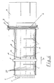
- a laminated glass cutting machine 1 according to the invention has an air cushion bridge table 2 with known Aufstellarmen 3 for a manual feed.
- a feed unit (indicated) 5 available on a narrow side or feed side 4 of the air cushion bridge table 2 .
- a laminated glass cutting device 7 is present on the opposite narrow side 6 (cutting side) .
- the Laminated glass cutting device 7 has a width across the Lucaskissen vitenticians 2 at the height of the narrow side 6 extending Cutting bridge 8 and a processing table 9, the with a gap (not shown) attached to the narrow side 6 is.
- Table longitudinal direction (Y direction) 10 Between the narrow side 4 and the cutting bridge 8 is in Table longitudinal direction (Y direction) 10 a positioning bridge 11th movably arranged.
- the positioning bridge 11 spans the Air cushion bridge table 2 and is at the longitudinal edges 12, 13th slidably mounted drivable.
- the gripping devices 14 are with respect to the longitudinal extension of the positioning bridge 11 with irregular Spaced apart, with different gripping wide glass panels or plates 17, the distances between the gripping means 14 from the longitudinal edge 13 to the longitudinal edge 12 going on.
- the distances between the gripping devices 14 are especially adapted to standard formats.
- the gripping devices 14 are on one of the cutting bridge 8 facing surface or wall 15 at the positioning bridge 11 arranged, in particular screwed.
- the wall 15 adjacent is a lifting device 16 for lifting the gripping device 14 above the level of a glass panel 17 available.
- the Lifting device 16 is for example one with a pneumatic Piston-cylinder unit 18 between a fastening device 19 and the remaining gripping means 14 arranged Lifting device 16.
- the gripping device 14 has an elongate gripper carrier 20 on.
- the gripper carrier 20 can be raised with the lifting device 16 and lowered connected.
- On the gripper carrier 20 are the end Gripper 21, 22 formed with gripping claws 23, wherein a gripper 21 of the positioning bridge 11 is remote and a gripper 22nd facing the positioning bridge 11 and obliquely below this is arranged.
- the grippers 21, 22 are formed in a conventional manner and are provided with an actuator 24, in particular a piston-cylinder unit 24 is actuated.
- an actuator 24 may be present, it may but also both grippers 21, 22 with a single actuator 24 are operated.
- both claws 23 approached each other.
- a lower claw 23 is located thus inevitably below the level of one on the table 2 resting disc.
- the table 2 has along its longitudinal extent in alignment with the trajectory of the gripper devices 14 grooves 27.
- Adjacent to the grippers 21, 22 are on the gripping device 14 sensors 28 available.
- the sensors 28 serve to capture a defined gripping depth.
- the gripping depth is dimensioned so that the claws 23 a panel 17 only engage in de-layered edge regions 29.
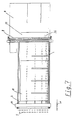
- a glass panel 17 can on the Aufstellarme 3 (Fig. 5) on the Air cushion bridge table 2 are placed so that the glass panel 17 between the positioning bridge 11 and the cutting bridge. 8 arrives.
- the glass sheet 17 is connected to the front grippers 21st (Fig. 6) gripped in the stripped edge area and along the Conveying direction (arrow 30) under the cutting bridge 8 promoted, up to the conveying direction behind the cutting bridge 8 a disc surface comes to lie, the one to be cut off Disc surface corresponds.
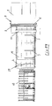
- the glass plate After cutting ( Figure 7), the glass plate is removed from the positioning bridge and still attacking the glass panel front grippers 21 counter to the conveying direction (arrow 31) of the cutting bridge 8 pulled away. Opposite of the positioning bridge 11 remains a cut glass panel section 33 on the processing table 9. For subsequent cutting steps on the cut glass panel portion 33, the glass sheet 17 must are moved away from the cutting bridge 8, wherein in one rear stop of the positioning bridge 11 (FIG. 7) the front Gripper 21, the glass panel 17 let go and then on the Glass panel 17 are to be moved to the cutting bridge 8, wherein lifted the gripper with the device 16 on the glass sheet 17 are.
- the gripping means 14 are again in the Grooves 27 lowered and the glass panel 17 with the rear Grippers 22 gripped in demolished edge areas and continue along the counter-conveying direction (arrow 31) of the cutting bridge 8 conveyed away until a sensor 35 is released.
- a Rotary suction pad 36 sucked from below and then by 90 ° under the cutting bridge 8 on the air cushion bridge table 2 turned (Fig. 9).
- the glass sheet 17 of the rear grippers 22 released and the positioning bridge 11 fed to the glass panel section 33 and a number of grippers 21 facing away from the cutting bridge 8 Narrow side 33 a gripped with grippers 21, wherein the number of Gripper 21 to the width of the glass panel section 33 and the Length of the narrow side 33a is tuned.
- the Positioning bridge with the glass panel section 33 along the Direction 30 driven under the cutting bridge 8 and of the Glass panel section 33 cut off a corresponding piece 37 and further conveyed to the processing table 9 (Fig. 10).
- one such cutting machine can, for example, an automatic Feed 40 upstream, with automatic loading 40, for example, a roller conveyor with Kipparmen 40th Roll over a large glass panel 17 onto the air cushion bridge table 2 auf formulan along the conveying direction 30 can.
- the promotion takes place while (Fig. 15), to a Part of the glass sheet 17 from the roller conveyor 40 on the air cushion bridge table 2 is funded.
- the positioning bridge 8 is in the counter-conveying direction 31 to move on the panel 17 until the gripper 22, the panel 17th grab and then along the conveying direction 30 on the To move cutting bridge 8 (Fig. 17).
- both top and bottom Cutting wheels arranged around an axis normal to the surface the glass sheet 17 are rotatably driven.
- These cutting wheels are thus able, not only along the cutting bridge 8, i.e. Can cut across the glass panel 17, but can in each Cut direction.
- Positioning bridge 8 can thereby any contours be cut, depending on the feed or retraction speed and the feed rate of the cutting wheel and the direction of the cutting wheel any Cut on a board 17 is feasible. This is it thus according to the invention for the first time possible, in laminated glass arbitrary Fully automatic cutting contours.
- the laminated glass cutting machine according to the invention makes it possible a simpler structure, as on the air cushion bridge table no additional conveyors are needed.
- any contour can be cut with laminated glass can. So far, such cuts were generated manually, wherein the glass plate was first cut on one side, then was turned and then cut on the other side. This had significant inaccuracies and a very big one Time expenditure result, which or which with the invention is avoided.
Landscapes
- Chemical & Material Sciences (AREA)
- Engineering & Computer Science (AREA)
- Materials Engineering (AREA)
- Organic Chemistry (AREA)
- Re-Forming, After-Treatment, Cutting And Transporting Of Glass Products (AREA)
- Joining Of Glass To Other Materials (AREA)
Priority Applications (2)
| Application Number | Priority Date | Filing Date | Title |
|---|---|---|---|
| EP05013575A EP1577273B1 (fr) | 2001-11-26 | 2002-10-01 | Dispositif et procédé pour couper du verre feuilleté selon un contour quelconque |
| EP06013857A EP1752425B1 (fr) | 2001-11-26 | 2002-10-01 | Dispositif de découpe de verre feuilleté et procédé pour positionner de verre feuilleté à découper |
Applications Claiming Priority (2)
| Application Number | Priority Date | Filing Date | Title |
|---|---|---|---|
| DE2001157833 DE10157833B4 (de) | 2001-11-26 | 2001-11-26 | Vorrichtung zum Aufteilen einer Verbundglastafel in einzelne Verbundglasscheiben und Verfahren zum Positionieren einer Verbundglastafel auf einer Verbundglasschneidanlage |
| DE10157833 | 2001-11-26 |
Related Child Applications (2)
| Application Number | Title | Priority Date | Filing Date |
|---|---|---|---|
| EP06013857A Division EP1752425B1 (fr) | 2001-11-26 | 2002-10-01 | Dispositif de découpe de verre feuilleté et procédé pour positionner de verre feuilleté à découper |
| EP05013575A Division EP1577273B1 (fr) | 2001-11-26 | 2002-10-01 | Dispositif et procédé pour couper du verre feuilleté selon un contour quelconque |
Publications (3)
| Publication Number | Publication Date |
|---|---|
| EP1314703A2 true EP1314703A2 (fr) | 2003-05-28 |
| EP1314703A3 EP1314703A3 (fr) | 2004-06-30 |
| EP1314703B1 EP1314703B1 (fr) | 2007-05-02 |
Family
ID=7706949
Family Applications (3)
| Application Number | Title | Priority Date | Filing Date |
|---|---|---|---|
| EP02021894A Expired - Lifetime EP1314703B1 (fr) | 2001-11-26 | 2002-10-01 | Appareil de découpe de verre feuilleté et procédé |
| EP06013857A Expired - Lifetime EP1752425B1 (fr) | 2001-11-26 | 2002-10-01 | Dispositif de découpe de verre feuilleté et procédé pour positionner de verre feuilleté à découper |
| EP05013575A Expired - Lifetime EP1577273B1 (fr) | 2001-11-26 | 2002-10-01 | Dispositif et procédé pour couper du verre feuilleté selon un contour quelconque |
Family Applications After (2)
| Application Number | Title | Priority Date | Filing Date |
|---|---|---|---|
| EP06013857A Expired - Lifetime EP1752425B1 (fr) | 2001-11-26 | 2002-10-01 | Dispositif de découpe de verre feuilleté et procédé pour positionner de verre feuilleté à découper |
| EP05013575A Expired - Lifetime EP1577273B1 (fr) | 2001-11-26 | 2002-10-01 | Dispositif et procédé pour couper du verre feuilleté selon un contour quelconque |
Country Status (4)
| Country | Link |
|---|---|
| EP (3) | EP1314703B1 (fr) |
| AT (3) | ATE361264T1 (fr) |
| DE (3) | DE10164872B4 (fr) |
| ES (3) | ES2203352T1 (fr) |
Cited By (5)
| Publication number | Priority date | Publication date | Assignee | Title |
|---|---|---|---|---|
| EP1264803A3 (fr) * | 2001-06-05 | 2004-04-28 | HEGLA Fahrzeug- u. Maschinenbau GmbH & Co. KG | Procédé et appareil pour découper du verre feuilleté |
| ITTO20100141A1 (it) * | 2010-02-26 | 2011-08-27 | Bottero Spa | Metodo per il taglio di una lastra di vetro |
| ITTO20100765A1 (it) * | 2010-09-20 | 2012-03-21 | Bottero Spa | Metodo e impianto per il taglio di lastre di vetro |
| EP3184473A1 (fr) * | 2015-12-21 | 2017-06-28 | Macotec S.R.L. | Table de chargement et d'alimentation, en particulier pour des lignes de découpe pour verre feuilleté et/ou monolithique |
| CN113830557A (zh) * | 2021-08-04 | 2021-12-24 | 甘肃光轩高端装备产业有限公司 | 玻璃卸载装置 |
Families Citing this family (7)
| Publication number | Priority date | Publication date | Assignee | Title |
|---|---|---|---|---|
| DE102008048255A1 (de) | 2008-09-22 | 2010-04-01 | Hegla Gmbh & Co. Kg | Verfahren und Vorrichtung zum Trennen von Verbundsicherheitsglasscheiben aus Verbundsicherheitsglastafeln |
| IT1397279B1 (it) | 2009-10-27 | 2013-01-04 | Biesse Spa | Macchina e procedimento per eseguire operazioni di taglio su una lastra di vetro, in particolare una lastra di vetro stratificato, lungo una traiettoria predeterminata |
| WO2015084668A1 (fr) | 2013-12-03 | 2015-06-11 | Corning Incorporated | Appareil et procédé pour le coupage d'une vitre |
| DE102016104273B4 (de) * | 2016-03-09 | 2021-02-04 | Hegla Gmbh & Co. Kg | Verfahren und Vorrichtung zur Behandlung von Flachglaseinheiten an einer glasverarbeitenden Anlage und Glasverarbeitende Anlage |
| CN109399901B (zh) * | 2018-10-09 | 2021-09-10 | 成都中光电科技有限公司 | 一种分体式推挡装置 |
| ES3054106T3 (en) * | 2021-02-16 | 2026-01-29 | Tur & Dev Sl | Glass processing table for processing glass |
| CN114538765B (zh) * | 2022-02-23 | 2023-07-21 | 苏州威创达智能设备有限公司 | 一种基于自动捡片机的双层玻璃耳料的去除方法 |
Family Cites Families (12)
| Publication number | Priority date | Publication date | Assignee | Title |
|---|---|---|---|---|
| US2328405A (en) * | 1941-07-17 | 1943-08-31 | Libbey Owens Ford Glass Co | Cutting machine |
| BE646550A (fr) * | 1963-04-29 | 1964-10-14 | ||
| DE3230554C2 (de) | 1982-04-28 | 1984-07-26 | GTI Glastechnische Industrie Peter Lisec, GmbH, Amstetten | Verfahren und Vorrichtung zum Schneiden von Verbundglas |
| IT1222060B (it) * | 1987-07-17 | 1990-08-31 | Vetreria Lorenzo Snc Di Giorgi | Apparecchiatura automatica particolarmente studiata per il taglio di lastre di vetro singole e doppie |
| DE4234536C2 (de) * | 1992-10-14 | 1998-08-27 | Armatec Maschinentechnik Gmbh | Anlage zum Schneiden von Glasscheiben |
| DE19600348C2 (de) | 1996-01-08 | 2001-11-22 | Lewecke Maschb Gmbh | Regalanlage für Platten |
| DE29608724U1 (de) * | 1996-05-14 | 1997-06-26 | Hegla Fahrzeug- Und Maschinenbau Gmbh & Co Kg, 37688 Beverungen | Vorrichtung zum Trennen von Glastafeln |
| IT1288673B1 (it) * | 1996-10-14 | 1998-09-23 | For El Base Di Vianello Fortun | Macchina per il taglio del vetro stratificato |
| DE19822282C1 (de) | 1998-05-18 | 1999-07-01 | Torgauer Maschinenbau Gmbh | Vorrichtung zum Glasschneiden |
| WO2000072062A1 (fr) | 1999-05-21 | 2000-11-30 | British Telecommunications Public Limited Company | Guides d'ondes optiques planaires pourvus de sillons |
| IT1311460B1 (it) | 1999-11-19 | 2002-03-12 | Bottero Spa | Impianto per il troncaggio di lastre di vetro incise. |
| IT1319624B1 (it) * | 2000-01-14 | 2003-10-20 | Bottero Spa | Unita' per l'incisione di una lastra di vetro stratificata. |
-
2001
- 2001-11-26 DE DE10164872A patent/DE10164872B4/de not_active Expired - Lifetime
- 2001-11-26 DE DE20121935U patent/DE20121935U1/de not_active Expired - Lifetime
-
2002
- 2002-10-01 AT AT02021894T patent/ATE361264T1/de not_active IP Right Cessation
- 2002-10-01 ES ES02021894T patent/ES2203352T1/es active Pending
- 2002-10-01 DE DE50210065T patent/DE50210065D1/de not_active Expired - Lifetime
- 2002-10-01 AT AT05013575T patent/ATE540904T1/de active
- 2002-10-01 EP EP02021894A patent/EP1314703B1/fr not_active Expired - Lifetime
- 2002-10-01 ES ES05013575T patent/ES2380602T3/es not_active Expired - Lifetime
- 2002-10-01 EP EP06013857A patent/EP1752425B1/fr not_active Expired - Lifetime
- 2002-10-01 ES ES06013857T patent/ES2377415T3/es not_active Expired - Lifetime
- 2002-10-01 EP EP05013575A patent/EP1577273B1/fr not_active Expired - Lifetime
- 2002-10-01 AT AT06013857T patent/ATE536334T1/de active
Cited By (6)
| Publication number | Priority date | Publication date | Assignee | Title |
|---|---|---|---|---|
| EP1264803A3 (fr) * | 2001-06-05 | 2004-04-28 | HEGLA Fahrzeug- u. Maschinenbau GmbH & Co. KG | Procédé et appareil pour découper du verre feuilleté |
| ITTO20100141A1 (it) * | 2010-02-26 | 2011-08-27 | Bottero Spa | Metodo per il taglio di una lastra di vetro |
| ITTO20100765A1 (it) * | 2010-09-20 | 2012-03-21 | Bottero Spa | Metodo e impianto per il taglio di lastre di vetro |
| EP2431339A1 (fr) * | 2010-09-20 | 2012-03-21 | Bottero S.p.A. | Procédé de découpe de feuilles de verre et système |
| EP3184473A1 (fr) * | 2015-12-21 | 2017-06-28 | Macotec S.R.L. | Table de chargement et d'alimentation, en particulier pour des lignes de découpe pour verre feuilleté et/ou monolithique |
| CN113830557A (zh) * | 2021-08-04 | 2021-12-24 | 甘肃光轩高端装备产业有限公司 | 玻璃卸载装置 |
Also Published As
| Publication number | Publication date |
|---|---|
| ATE536334T1 (de) | 2011-12-15 |
| ATE361264T1 (de) | 2007-05-15 |
| EP1314703B1 (fr) | 2007-05-02 |
| ES2203352T1 (es) | 2004-04-16 |
| DE10164872B4 (de) | 2008-04-03 |
| ES2380602T3 (es) | 2012-05-16 |
| EP1314703A3 (fr) | 2004-06-30 |
| EP1577273A2 (fr) | 2005-09-21 |
| ATE540904T1 (de) | 2012-01-15 |
| DE50210065D1 (de) | 2007-06-14 |
| DE20121935U1 (de) | 2003-09-25 |
| EP1577273A3 (fr) | 2005-11-30 |
| EP1752425A1 (fr) | 2007-02-14 |
| ES2377415T3 (es) | 2012-03-27 |
| EP1752425B1 (fr) | 2011-12-07 |
| EP1577273B1 (fr) | 2012-01-11 |
Similar Documents
| Publication | Publication Date | Title |
|---|---|---|
| DE4123929C2 (de) | Verfahren und Vorrichtung zum Zerteilen von Flachglastafeln | |
| EP3227072B1 (fr) | Équipement diviseur de panneaux pour diviser des pièces en forme de panneaux ainsi que son procédé de fonctionnement | |
| AT401172B (de) | Verfahren zum teilen von glastafeln in zuschnitte | |
| EP2832507B1 (fr) | Procédé destiné et scie à panneaux horizontale au sciage de pièces à usiner | |
| DE3632895A1 (de) | Vorrichtung und verfahren zum abziehen von schutzfilmen | |
| EP1440922A2 (fr) | Procédé et appareil pour déplacer et positioner des feuilles de verre | |
| EP3867203B1 (fr) | Dispositif de découpe de verre feuilleté et procédé pour découper des panneaux de verre feuilleté | |
| EP0564758B1 (fr) | Procédé et appareil pour diviser des plaques en verre en parties | |
| DE19839924A1 (de) | Vorrichtung zur Abnahme von Folien von einem Folienstapel in einer Stapelstation und zur Ablage der abgenommenen Folien in einer Zusammenlegestation | |
| EP1752425B1 (fr) | Dispositif de découpe de verre feuilleté et procédé pour positionner de verre feuilleté à découper | |
| DE10157833B4 (de) | Vorrichtung zum Aufteilen einer Verbundglastafel in einzelne Verbundglasscheiben und Verfahren zum Positionieren einer Verbundglastafel auf einer Verbundglasschneidanlage | |
| DE3832215C2 (de) | Vorrichtung zum Trennen von Tafeln | |
| EP1475356B1 (fr) | Méthode et procédé de découpe de feuilles de verre | |
| EP1111148A1 (fr) | Dispositif et procédé pour fabriquer des tableaux muraux | |
| EP1611039B1 (fr) | Dispositif de transport, notamment pour des pieces a usiner en forme de plaques | |
| EP1889699B1 (fr) | Dispositif destiné au tri de déchets de pièces à usiner, avec une machine de sciage, notamment une tronçonneuse d'optimisation et procédé faisant appel à un tel dispositif | |
| DE4013417A1 (de) | Verfahren zum entnehmen und ablegen eines ausgestanzten blattstapels o. dgl. stapel blattfoermigen werkstoffs aus einem gesamtstapel sowie vorrichtung hierfuer | |
| DE202014008305U1 (de) | Vorrichtung zum Aufteilen einer Glastafel, insbesondere Verbundglastafel, in einzelne Glasscheiben, insbesondere Verbundglasscheiben | |
| DE1471967B2 (de) | Glasschneidemaschine und Förder- und Ausrichteinrichtung für eine Glasscheibe | |
| DE102005002532A1 (de) | Vorrichtung und Verfahren zum automatisierten und zeitgleichen Bereitstellen und Wechseln von mindestens zwei Rollen aus Papierbahnen oder dergleichen für einen nachgeordneten Formatschneider | |
| EP0841844A2 (fr) | Méthode et appareil pour générer un flux déterminé de circuits imprimés transportés horizontalement | |
| DE69319518T2 (de) | Verfahren und Vorrichtung zum Zerschneiden von grossen Glasplatten in kleinere Abmessungen | |
| DE202007016420U1 (de) | Fördervorrichtung für plattenförmige Werkstücke | |
| DE68905648T2 (de) | Verfahren und einrichtung zum stapeln von mit einer schere produzierten blechen, insbesondere aus einem blechband. | |
| DE19839923C2 (de) | Vorrichtung zur Abnahme von Folien von einem Folienstapel in einer Stapelstation und zur Ablage der abgenommenen Folien in einer Zusammenlegestation |
Legal Events
| Date | Code | Title | Description |
|---|---|---|---|
| PUAI | Public reference made under article 153(3) epc to a published international application that has entered the european phase |
Free format text: ORIGINAL CODE: 0009012 |
|
| AK | Designated contracting states |
Designated state(s): AT BE BG CH CY CZ DE DK EE ES FI FR GB GR IE IT LI LU MC NL PT SE SK TR |
|
| AX | Request for extension of the european patent |
Extension state: AL LT LV MK RO SI |
|
| GBC | Gb: translation of claims filed (gb section 78(7)/1977) | ||
| EL | Fr: translation of claims filed | ||
| PUAL | Search report despatched |
Free format text: ORIGINAL CODE: 0009013 |
|
| AK | Designated contracting states |
Kind code of ref document: A3 Designated state(s): AT BE BG CH CY CZ DE DK EE ES FI FR GB GR IE IT LI LU MC NL PT SE SK TR |
|
| AX | Request for extension of the european patent |
Extension state: AL LT LV MK RO SI |
|
| RIC1 | Information provided on ipc code assigned before grant |
Ipc: 7C 03B 33/07 B Ipc: 7C 03B 33/027 B Ipc: 7B 65G 49/06 B Ipc: 7C 03B 33/03 A |
|
| 17P | Request for examination filed |
Effective date: 20040715 |
|
| AKX | Designation fees paid |
Designated state(s): AT BE BG CH CY CZ DE DK EE ES FI FR GB GR IE IT LI LU MC NL PT SE SK TR |
|
| 17Q | First examination report despatched |
Effective date: 20050315 |
|
| GRAP | Despatch of communication of intention to grant a patent |
Free format text: ORIGINAL CODE: EPIDOSNIGR1 |
|
| RTI1 | Title (correction) |
Free format text: APPARATUS TO CUT LAMINATED GLASS AND METHOD |
|
| GRAS | Grant fee paid |
Free format text: ORIGINAL CODE: EPIDOSNIGR3 |
|
| GRAA | (expected) grant |
Free format text: ORIGINAL CODE: 0009210 |
|
| AK | Designated contracting states |
Kind code of ref document: B1 Designated state(s): AT BE BG CH CY CZ DE DK EE ES FI FR GB GR IE IT LI LU MC NL PT SE SK TR |
|
| PG25 | Lapsed in a contracting state [announced via postgrant information from national office to epo] |
Ref country code: FI Free format text: LAPSE BECAUSE OF FAILURE TO SUBMIT A TRANSLATION OF THE DESCRIPTION OR TO PAY THE FEE WITHIN THE PRESCRIBED TIME-LIMIT Effective date: 20070502 |
|
| REG | Reference to a national code |
Ref country code: GB Ref legal event code: FG4D Free format text: NOT ENGLISH |
|
| REG | Reference to a national code |
Ref country code: CH Ref legal event code: EP |
|
| REG | Reference to a national code |
Ref country code: IE Ref legal event code: FG4D Free format text: LANGUAGE OF EP DOCUMENT: GERMAN |
|
| REF | Corresponds to: |
Ref document number: 50210065 Country of ref document: DE Date of ref document: 20070614 Kind code of ref document: P |
|
| PG25 | Lapsed in a contracting state [announced via postgrant information from national office to epo] |
Ref country code: SE Free format text: LAPSE BECAUSE OF FAILURE TO SUBMIT A TRANSLATION OF THE DESCRIPTION OR TO PAY THE FEE WITHIN THE PRESCRIBED TIME-LIMIT Effective date: 20070802 |
|
| PG25 | Lapsed in a contracting state [announced via postgrant information from national office to epo] |
Ref country code: ES Free format text: LAPSE BECAUSE OF FAILURE TO SUBMIT A TRANSLATION OF THE DESCRIPTION OR TO PAY THE FEE WITHIN THE PRESCRIBED TIME-LIMIT Effective date: 20070813 |
|
| GBT | Gb: translation of ep patent filed (gb section 77(6)(a)/1977) |
Effective date: 20070808 |
|
| REG | Reference to a national code |
Ref country code: CH Ref legal event code: NV Representative=s name: TROESCH SCHEIDEGGER WERNER AG |
|
| ET | Fr: translation filed | ||
| NLV1 | Nl: lapsed or annulled due to failure to fulfill the requirements of art. 29p and 29m of the patents act | ||
| REG | Reference to a national code |
Ref country code: IE Ref legal event code: FD4D |
|
| PG25 | Lapsed in a contracting state [announced via postgrant information from national office to epo] |
Ref country code: BG Free format text: LAPSE BECAUSE OF FAILURE TO SUBMIT A TRANSLATION OF THE DESCRIPTION OR TO PAY THE FEE WITHIN THE PRESCRIBED TIME-LIMIT Effective date: 20070802 Ref country code: CZ Free format text: LAPSE BECAUSE OF FAILURE TO SUBMIT A TRANSLATION OF THE DESCRIPTION OR TO PAY THE FEE WITHIN THE PRESCRIBED TIME-LIMIT Effective date: 20070502 Ref country code: NL Free format text: LAPSE BECAUSE OF FAILURE TO SUBMIT A TRANSLATION OF THE DESCRIPTION OR TO PAY THE FEE WITHIN THE PRESCRIBED TIME-LIMIT Effective date: 20070502 Ref country code: PT Free format text: LAPSE BECAUSE OF FAILURE TO SUBMIT A TRANSLATION OF THE DESCRIPTION OR TO PAY THE FEE WITHIN THE PRESCRIBED TIME-LIMIT Effective date: 20071002 Ref country code: IE Free format text: LAPSE BECAUSE OF FAILURE TO SUBMIT A TRANSLATION OF THE DESCRIPTION OR TO PAY THE FEE WITHIN THE PRESCRIBED TIME-LIMIT Effective date: 20070502 Ref country code: DK Free format text: LAPSE BECAUSE OF FAILURE TO SUBMIT A TRANSLATION OF THE DESCRIPTION OR TO PAY THE FEE WITHIN THE PRESCRIBED TIME-LIMIT Effective date: 20070502 |
|
| PG25 | Lapsed in a contracting state [announced via postgrant information from national office to epo] |
Ref country code: SK Free format text: LAPSE BECAUSE OF FAILURE TO SUBMIT A TRANSLATION OF THE DESCRIPTION OR TO PAY THE FEE WITHIN THE PRESCRIBED TIME-LIMIT Effective date: 20070502 |
|
| PLBE | No opposition filed within time limit |
Free format text: ORIGINAL CODE: 0009261 |
|
| STAA | Information on the status of an ep patent application or granted ep patent |
Free format text: STATUS: NO OPPOSITION FILED WITHIN TIME LIMIT |
|
| 26N | No opposition filed |
Effective date: 20080205 |
|
| BERE | Be: lapsed |
Owner name: HEGLA FAHRZEUG- U. MASCHINENBAU G.M.B.H. & CO. KG Effective date: 20071031 |
|
| PG25 | Lapsed in a contracting state [announced via postgrant information from national office to epo] |
Ref country code: GR Free format text: LAPSE BECAUSE OF FAILURE TO SUBMIT A TRANSLATION OF THE DESCRIPTION OR TO PAY THE FEE WITHIN THE PRESCRIBED TIME-LIMIT Effective date: 20070803 |
|
| PG25 | Lapsed in a contracting state [announced via postgrant information from national office to epo] |
Ref country code: MC Free format text: LAPSE BECAUSE OF NON-PAYMENT OF DUE FEES Effective date: 20071031 |
|
| PG25 | Lapsed in a contracting state [announced via postgrant information from national office to epo] |
Ref country code: BE Free format text: LAPSE BECAUSE OF NON-PAYMENT OF DUE FEES Effective date: 20071031 |
|
| PG25 | Lapsed in a contracting state [announced via postgrant information from national office to epo] |
Ref country code: EE Free format text: LAPSE BECAUSE OF FAILURE TO SUBMIT A TRANSLATION OF THE DESCRIPTION OR TO PAY THE FEE WITHIN THE PRESCRIBED TIME-LIMIT Effective date: 20070502 |
|
| PG25 | Lapsed in a contracting state [announced via postgrant information from national office to epo] |
Ref country code: CY Free format text: LAPSE BECAUSE OF FAILURE TO SUBMIT A TRANSLATION OF THE DESCRIPTION OR TO PAY THE FEE WITHIN THE PRESCRIBED TIME-LIMIT Effective date: 20070502 |
|
| PG25 | Lapsed in a contracting state [announced via postgrant information from national office to epo] |
Ref country code: LU Free format text: LAPSE BECAUSE OF NON-PAYMENT OF DUE FEES Effective date: 20071001 |
|
| PG25 | Lapsed in a contracting state [announced via postgrant information from national office to epo] |
Ref country code: TR Free format text: LAPSE BECAUSE OF FAILURE TO SUBMIT A TRANSLATION OF THE DESCRIPTION OR TO PAY THE FEE WITHIN THE PRESCRIBED TIME-LIMIT Effective date: 20070502 |
|
| PGFP | Annual fee paid to national office [announced via postgrant information from national office to epo] |
Ref country code: GB Payment date: 20090930 Year of fee payment: 8 |
|
| PGFP | Annual fee paid to national office [announced via postgrant information from national office to epo] |
Ref country code: AT Payment date: 20091014 Year of fee payment: 8 |
|
| PGFP | Annual fee paid to national office [announced via postgrant information from national office to epo] |
Ref country code: FR Payment date: 20091116 Year of fee payment: 8 |
|
| GBPC | Gb: european patent ceased through non-payment of renewal fee |
Effective date: 20101001 |
|
| PG25 | Lapsed in a contracting state [announced via postgrant information from national office to epo] |
Ref country code: FR Free format text: LAPSE BECAUSE OF NON-PAYMENT OF DUE FEES Effective date: 20101102 |
|
| REG | Reference to a national code |
Ref country code: FR Ref legal event code: ST Effective date: 20110630 |
|
| PG25 | Lapsed in a contracting state [announced via postgrant information from national office to epo] |
Ref country code: AT Free format text: LAPSE BECAUSE OF NON-PAYMENT OF DUE FEES Effective date: 20101001 Ref country code: GB Free format text: LAPSE BECAUSE OF NON-PAYMENT OF DUE FEES Effective date: 20101001 |
|
| PGFP | Annual fee paid to national office [announced via postgrant information from national office to epo] |
Ref country code: CH Payment date: 20111018 Year of fee payment: 10 |
|
| REG | Reference to a national code |
Ref country code: CH Ref legal event code: PL |
|
| PG25 | Lapsed in a contracting state [announced via postgrant information from national office to epo] |
Ref country code: CH Free format text: LAPSE BECAUSE OF NON-PAYMENT OF DUE FEES Effective date: 20121031 Ref country code: LI Free format text: LAPSE BECAUSE OF NON-PAYMENT OF DUE FEES Effective date: 20121031 |
|
| PGFP | Annual fee paid to national office [announced via postgrant information from national office to epo] |
Ref country code: IT Payment date: 20210901 Year of fee payment: 20 |
|
| PGFP | Annual fee paid to national office [announced via postgrant information from national office to epo] |
Ref country code: DE Payment date: 20211227 Year of fee payment: 20 |
|
| REG | Reference to a national code |
Ref country code: DE Ref legal event code: R071 Ref document number: 50210065 Country of ref document: DE |