EP1314703B1 - Appareil de découpe de verre feuilleté et procédé - Google Patents
Appareil de découpe de verre feuilleté et procédé Download PDFInfo
- Publication number
- EP1314703B1 EP1314703B1 EP02021894A EP02021894A EP1314703B1 EP 1314703 B1 EP1314703 B1 EP 1314703B1 EP 02021894 A EP02021894 A EP 02021894A EP 02021894 A EP02021894 A EP 02021894A EP 1314703 B1 EP1314703 B1 EP 1314703B1
- Authority
- EP
- European Patent Office
- Prior art keywords
- cutting
- laminated glass
- bridge
- glass sheet
- gripping
- Prior art date
- Legal status (The legal status is an assumption and is not a legal conclusion. Google has not performed a legal analysis and makes no representation as to the accuracy of the status listed.)
- Expired - Lifetime
Links
- 239000005340 laminated glass Substances 0.000 title claims description 68
- 238000000034 method Methods 0.000 title claims description 9
- 239000011521 glass Substances 0.000 claims abstract description 63
- 238000009434 installation Methods 0.000 claims description 8
- 210000000078 claw Anatomy 0.000 claims description 6
- 238000011144 upstream manufacturing Methods 0.000 claims description 3
- 238000006073 displacement reaction Methods 0.000 claims description 2
- 230000001788 irregular Effects 0.000 claims description 2
- 238000003754 machining Methods 0.000 claims description 2
- 239000011248 coating agent Substances 0.000 claims 1
- 238000000576 coating method Methods 0.000 claims 1
- 239000002131 composite material Substances 0.000 abstract description 7
- 238000005516 engineering process Methods 0.000 description 2
- 230000001419 dependent effect Effects 0.000 description 1
- 238000011161 development Methods 0.000 description 1
- 230000018109 developmental process Effects 0.000 description 1
- 239000011888 foil Substances 0.000 description 1
- 230000000284 resting effect Effects 0.000 description 1
Images








Classifications
-
- C—CHEMISTRY; METALLURGY
- C03—GLASS; MINERAL OR SLAG WOOL
- C03B—MANUFACTURE, SHAPING, OR SUPPLEMENTARY PROCESSES
- C03B33/00—Severing cooled glass
- C03B33/07—Cutting armoured, multi-layered, coated or laminated, glass products
- C03B33/076—Laminated glass comprising interlayers
- C03B33/078—Polymeric interlayers
-
- B—PERFORMING OPERATIONS; TRANSPORTING
- B65—CONVEYING; PACKING; STORING; HANDLING THIN OR FILAMENTARY MATERIAL
- B65G—TRANSPORT OR STORAGE DEVICES, e.g. CONVEYORS FOR LOADING OR TIPPING, SHOP CONVEYOR SYSTEMS OR PNEUMATIC TUBE CONVEYORS
- B65G49/00—Conveying systems characterised by their application for specified purposes not otherwise provided for
- B65G49/05—Conveying systems characterised by their application for specified purposes not otherwise provided for for fragile or damageable materials or articles
- B65G49/06—Conveying systems characterised by their application for specified purposes not otherwise provided for for fragile or damageable materials or articles for fragile sheets, e.g. glass
- B65G49/068—Stacking or destacking devices; Means for preventing damage to stacked sheets, e.g. spaces
-
- C—CHEMISTRY; METALLURGY
- C03—GLASS; MINERAL OR SLAG WOOL
- C03B—MANUFACTURE, SHAPING, OR SUPPLEMENTARY PROCESSES
- C03B33/00—Severing cooled glass
- C03B33/02—Cutting or splitting sheet glass or ribbons; Apparatus or machines therefor
- C03B33/0207—Cutting or splitting sheet glass or ribbons; Apparatus or machines therefor the sheet being in a substantially vertical plane
-
- C—CHEMISTRY; METALLURGY
- C03—GLASS; MINERAL OR SLAG WOOL
- C03B—MANUFACTURE, SHAPING, OR SUPPLEMENTARY PROCESSES
- C03B33/00—Severing cooled glass
- C03B33/02—Cutting or splitting sheet glass or ribbons; Apparatus or machines therefor
- C03B33/023—Cutting or splitting sheet glass or ribbons; Apparatus or machines therefor the sheet or ribbon being in a horizontal position
- C03B33/03—Glass cutting tables; Apparatus for transporting or handling sheet glass during the cutting or breaking operations
-
- B—PERFORMING OPERATIONS; TRANSPORTING
- B65—CONVEYING; PACKING; STORING; HANDLING THIN OR FILAMENTARY MATERIAL
- B65G—TRANSPORT OR STORAGE DEVICES, e.g. CONVEYORS FOR LOADING OR TIPPING, SHOP CONVEYOR SYSTEMS OR PNEUMATIC TUBE CONVEYORS
- B65G2249/00—Aspects relating to conveying systems for the manufacture of fragile sheets
- B65G2249/04—Arrangements of vacuum systems or suction cups
Definitions
- the invention relates to a laminated glass cutting installation according to the preamble of claim 1 and to a method for positioning a laminated glass panel on the laminated glass cutting installation.
- Laminated glass is understood as meaning a disk formed from two glass plates, wherein a first inner plate consists of a usually uncoated glass and a second outer plate consists of a glass coated in particular, in particular provided with a heat protection layer. The two glass plates are glued together with a foil.
- laminated glass cutting machines are used.
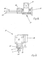
- a known laminated glass cutting installation 200 (FIG. 19) has a travel bridge 201, a support table 202 and a cutting bridge 203.
- Grippers 204 whose gripper jaw can clamp a laminated glass pane 205, are arranged on the travel bridge 201 towards the cutting bridge 203. Since the disc 205 rests on the support table 202, lower jaws of the grippers 204 must run in grooves 206 in the support table 202. With the grippers 204, the disk 205, after it has been promoted on the support table 202 with suitable transport means such as transport rollers or conveyor belts or manually placed with Aufstellarmen 207, gripped and pushed onto the cutting bridge 203.
- suitable transport means such as transport rollers or conveyor belts or manually placed with Aufstellarmen 207
- Such a laminated glass cutting system is known for example from DE 32 30 554 A1. After cutting with a cutting bridge, the glass sheets are bent along the score line to create a continuous tear in the region of the score line. Subsequently or at the same time, the glass plates are pulled apart and the film in the gap is melted or separated by heat.
- laminated glass cutting equipment is disadvantageous that they require in addition to a considerable length an expensive transport technology, the laminated glass panes are cut and separable only along straight lines parallel to the table edges or glass edges.
- EP 1 118 592 A1 describes a device for cutting laminated glass panels, which has a support table for laying laminated glass panels and a laminated glass cutting device, wherein the laminated glass cutting device has a cutting bridge extending across the width of the support table at the level of one side of the support table.
- the cutting bridge is used for cutting or scribing the composite glass panel.
- the device according to EP 1 118 592 A1 has a displacement or positioning bridge arranged counter to the support bridge for the cutting bridge and displaceable for displacing and positioning the composite glass panel on the support table, wherein the positioning bridge comprises a vertical axis perpendicular to the composite glass panel having rotatable suction pads, with which the composite glass panel is gripped from above and which serves for rotating, aligning and moving the composite glass panel on the support table, u. a. to be able to cut them along angled and curved lines.
- the object of the invention is to provide a laminated glass cutting system that is short and simple in terms of transport technology is constructed and can be performed with any cuts.
- a positioning bridge which has grippers on both sides, so that the glass plates can be both pulled and pushed. This results in a surprising way, a significant reduction in the overall length. Furthermore, a glass plate can be actively pulled onto the support table, so that upstream transport devices can be simplified or omitted. Furthermore, a more accurate positioning and edge parallelism is achieved.
- the invention further provides for the cutting or scoring devices to be rotatable on the cutting bridge and to be movable along the cutting bridge. In combination with the positioning bridge, any cuts, even round or curved cuts are possible. This especially automated computer-controlled.
- a laminated glass cutting installation 1 according to the invention preferably has as a support table an air cushion bridge table 2 with erecting arms 3 known per se for manual loading.
- a Feeding unit (indicated) 5 available on a narrow side or feed side 4 of the air cushion bridge table 2 is in the air cushion bridge table 2 .
- a laminated glass cutting device 7 is present on the opposite narrow side 6 (cutting side) .
- the laminated glass cutting device 7 has a over the width of the air cushion bridge table 2 at the height of the narrow side 6 extending cutting bridge 8 and a machining table 9, which is attached with a gap (not shown) to the narrow side 6.
- a positioning 11 is arranged movable between the narrow side 4 and the cutting bridge 8 in the table longitudinal direction (Y-direction) 10 a positioning 11 is arranged movable.
- the positioning bridge 11 spans the air cushion bridge table 2 and is slidably mounted drivable at the longitudinal edges 12, 13.
- a plurality of gripping means 14 are formed.
- the gripping devices 14 are arranged with respect to the longitudinal extent of the positioning bridge 11 with irregular distances from each other, wherein the distances between the gripping means 14 from the longitudinal edge 13 to the longitudinal edge 12 to continue to grasp glass plates or plates 17 of different widths.
- the distances between the gripping devices 14 are particularly matched to standard formats.
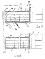
- the gripping devices 14 are arranged, in particular screwed, on a surface or wall 15 facing the cutting bridge 8 on the positioning bridge 11. Adjacent to the wall 15 is a lifting device 16 for lifting the gripping device 14 above the level of a glass sheet 17.
- the lifting device 16 is, for example, a lifting device 16 arranged with a pneumatic piston-cylinder unit 18 between a fastening device 19 and the remaining gripper device 14.
- the gripping device 14 has an elongate gripper carrier 20.
- the gripper carrier 20 can be raised with the lifting device 16 and lowered connected.
- end gripper 21, 22 are formed with gripping jaws 23, wherein a gripper 21 of the positioning bridge 11 is remote from and a gripper 22 of the positioning bridge 11 facing and disposed obliquely below it.
- the grippers 21, 22 are formed in a manner known per se and are actuated by an actuating device 24, in particular a piston-cylinder unit 24.
- an actuator 24 may be present, but it can also be both grippers 21, 22 are operated with a single actuator 24.
- both claws 23 are closed to each other.
- a lower claw 23 is thus inevitably below the level of resting on the table 2 disc.
- the table 2 has along its longitudinal extent in alignment with the movement path of the gripper means 14 grooves 27.
- Adjacent to the grippers 21, 22 14 sensors 28 are provided on the gripping device. The sensors 28 serve to detect a defined gripping depth. The gripping depth is dimensioned such that the claws 23 engage a panel 17 only in demolished edge regions 29.
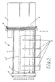
- a glass panel 17 can be placed on the air cushion bridge table 2 via the raising arms 3 (FIG. 5), so that the glass panel 17 passes between the positioning bridge 11 and the cutting bridge 8.
- the glass panel 17 is gripped with the front grippers 21 (FIG. 6) in the stripped edge area and conveyed along the conveying direction (arrow 30) under the cutting bridge 8, with reference to the conveying direction 30 behind the cutting bridge 8 a disc surface comes to rest, which corresponds to a slice surface to be cut off.
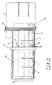
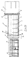
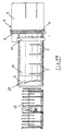
- the glass plate After cutting (FIG. 7), the glass plate is pulled away from the cutting bridge 8 by the positioning bridge and the front grippers 21, which still engage the glass panel, against the conveying direction (arrow 31). Opposite the positioning bridge 11 remains a cut glass panel section 33 on the processing table 9. For subsequent cutting steps on the cut glass panel section 33, the glass panel 17 must be moved away from the cutting bridge 8, wherein in a rear stop of the positioning bridge 11 (FIG Gripper 21 let go of the glass panel 17 and then to move over the glass sheet 17 on the cutting bridge 8, the grippers 21, 22 are raised with the device 16 on the glass sheet 17.
- the gripping devices 14 are lowered back into the grooves 27 and the glass panel 17 is gripped with the rear grippers 22 in stripped edge areas and further along the Gegen functioncardi (arrow 31) away from the cutting bridge 8, to a Sensor 35 is free.
- a Sensor 35 is free.
- it is sucked from below by a rotary suction plate 36 and then rotated by 90 ° under the cutting bridge 8 onto the air cushion bridge table 2 (FIG. 9).
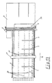
- the glass panel 17 is released from the rear grippers 22 and the positioning bridge 11 is fed onto the glass panel section 33 and with a number of grippers 21 at its the cutting bridge 8 facing away from narrow side 33a gripped with grippers 21, wherein the number of grippers 21 is matched to the width of the glass panel section 33 and the length of the narrow side 33a.
- the positioning bridge 11 is moved against the conveying direction (arrow 31) to the panel 17 and the panel 17 gripped with rear grippers 22 and pulled forward to the cutting bridge 8 along the conveying direction 30 ( Figure 11).
- the positioning bridge 11 is moved over the glass sheet 17 in the counter-conveying direction 31, wherein the entire gripping device 14 is raised with the device 16.
- the gripper device 14 is lowered back into the grooves 27 and fed to the panel 17 until the front gripper 21, the panel 17 engage (Fig. 12).
- the glass sheet 17 is moved along the conveying direction 30 again under the cutting bridge 8 until a desired piece of plate protrudes on the processing table 9.
- an automatic cutting device may be preceded by an automatic feed 40, wherein the automatic feed 40 may be, for example, a roller conveyor with tilting arms 40 which can convey a large glass sheet 17 onto the air cushion bridge table 2 along the conveying direction 30 via rollers.
- the promotion takes place while (Fig. 15) until a part of the glass sheet 17 is conveyed from the roller conveyor 40 on the air cushion bridge table 2.
- the positioning bridge 8 is moved in counterfeeding direction 31 onto the panel 17 until the grippers 22 grasp the panel 17 and subsequently move along the conveying direction 30 onto the cutting bridge 8 (FIG. 17).
- both top and bottom Cutting wheels are rotatably driven about an axis normal to the surface of the glass sheet 17.
- These cutting wheels are thus able to cut not only along the cutting bridge 8, ie transversely to the glass sheet 17, but can cut in any direction.
- arbitrary contours can be cut together with the positioning bridge 11 designed according to the invention since any desired cut on a panel 17 can be carried out depending on the feed or retraction speed and the feed rate of the cutting wheel and the direction of the cutting wheel. This makes it possible according to the invention for the first time to cut any contours fully automatically in laminated glass.
- the laminated glass cutting system according to the invention allows a simpler structure, since no additional conveyors are needed on the air cushion bridge table.
- any contour can be cut with laminated glass.
- cuts were made manually, with the glass sheet first cut on one side, then rotated, and then cut on the other side. This resulted in significant inaccuracies and a very large amount of time which is avoided with the invention.
Landscapes
- Chemical & Material Sciences (AREA)
- Engineering & Computer Science (AREA)
- Materials Engineering (AREA)
- Organic Chemistry (AREA)
- Re-Forming, After-Treatment, Cutting And Transporting Of Glass Products (AREA)
- Joining Of Glass To Other Materials (AREA)
Claims (19)
- Dispositif pour couper un panneau de verre de sécurité feuilleté (17)- comprenant une table de support (2) pour la pose de panneaux de verre de sécurité feuilleté (17), qui présente deux côtés étroits (4, 6) se faisant face, dont un côté étroit (6) est un côté de coupe (6) et- avec un dispositif de coupe de verre de sécurité feuilleté (7) qui présente un pont de coupe (8) s'étendant sur la largeur de la table de support (2) à la hauteur du côté de coupe (6), sur lequel est présent côté supérieur ou côté inférieur du panneau de verre de sécurité feuilleté (17) à traiter au moins un outil de coupe pour couper ou rayer le panneau de verre de sécurité feuilleté (17), et une table de traitement (9), qui est placée sur le côté de coupe (6),- un pont de positionnement (11) disposé au-dessus de la table de support (2) et pouvant faire des allers et retours le long d'une direction longitudinale de table (10) de la table de support (2) dans le sens contraire au dispositif de coupe de verre de sécurité feuilleté (7), pour le déplacement et le positionnement du panneau de verre de sécurité feuilleté (17) sur la table de support (2) avec au moins un dispositif de préhension (14) muni d'au moins une pince (21) de serrage avant, dont la mâchoire de préhension (25) formée par ses griffes de préhension (23) et destinée à saisir le panneau de verre de sécurité feuilleté (17), située dans la zone de bordure arrière, opposée à l'installation de coupe du verre de sécurité feuilleté (7), est dirigée vers le pont de coupe (8),caractérisé en ce que
sur le dispositif de préhension (14), est présente au moins une pince (22) arrière de serrage, dont la mâchoire de préhension (25) formée par ses griffes de préhension (23) part du pont de coupe (8), de sorte que le panneau de verre de sécurité feuilleté (17) peut être saisi également dans sa zone de bordure avant, tourné vers l'installation de coupe de verre de sécurité feuilleté (7) et peut être aussi bien tiré que poussé. - Dispositif selon la revendication 1,
caractérisé en ce que sur le pont de positionnement (11) est présente une pluralité de dispositifs de préhension (14), au moins une pince (21) avant de serrage et au moins une pince (22) arrière de serrage étant présentes sur le pont de positionnement (11) le long de l'extension longitudinale de la table de support (2) sur chaque dispositif de préhension (14). - Dispositif selon la revendication 1 ou 2,
caractérisé en ce que
les outils de coupe peuvent tourner librement ou de façon entraînée autour d'un axe perpendiculairement au sens de coupe et perpendiculairement au plan du panneau de verre de sécurité feuilleté et peuvent être déplacés le long du pont de coupe (8) transversalement au sens de transport d'un panneau de verre de sécurité feuilleté (17), de sorte que des contours de coupe quelconques peuvent être coupés. - Dispositif selon la revendication 2 et/ou 3,
caractérisé en ce que
les dispositifs de préhension (14) sont disposés avec des intervalles irréguliers entre eux par rapport à l'extension longitudinale du pont de positionnement (11), les espacements entre les dispositifs de préhension (14) allant d'une arête longitudinale (13) de la table de support (2) en direction d'une arête longitudinale (12) opposée devenant plus larges ou plus resserrés afin de saisir des panneaux de verre de sécurité feuilleté (17) de largeur différente. - Dispositif selon la revendication 4,
caractérisé en ce que
les espacements entre les dispositifs de préhension (14) sont adaptés au format standard de panneau de verre de sécurité feuilleté (17). - Dispositif selon l'une quelconque des revendications précédentes,
caractérisé en ce que
les dispositifs de préhension (14) présentent un dispositif de levage (16) pour l'élévation du dispositif de préhension (14) au-dessus du niveau d'un panneau de verre de sécurité feuilleté (17), de sorte que le pont de positionnement (11) peut franchir le panneau de verre de sécurité feuilleté (17) avec des dispositifs de préhension (14) relevés. - Dispositif selon la revendication 6,
caractérisé en ce que
le dispositif de levage (16) présente une unité piston-cylindre (18) pneumatique ou hydraulique ou un dispositif de déplacement par moteur électrique, qui est disposé entre un dispositif de fixation (19) et le dispositif de préhension (14) restant. - Dispositif selon la revendication 6 et/ou la revendication 7,
caractérisé en ce que
le dispositif de préhension (14) présente un support de pince (20) allongé, le support de pince (20) étant relié au dispositif de levage (16) de façon à pouvoir être soulevé et abaissé, les pinces (21, 22) étant réalisées côté extrémité sur le support de pince (20). - Dispositif selon l'une quelconque des revendications précédentes,
caractérisé en ce que
les pinces (21, 22) présentent chacune un dispositif d'actionnement (24) pour l'ouverture et la fermeture des mâchoires de préhension (25). - Dispositif selon la revendication 9,
caractérisé en ce que
le dispositif d'actionnement (24) est une unité piston-cylindre (24) pneumatique ou hydraulique ou une unité de positionnement (24) par moteur électrique. - Dispositif selon l'une quelconque des revendications précédentes,
caractérisé en ce que
chaque pince (21, 22) présente un dispositif d'actionnement (24) propre. - Dispositif selon l'une quelconque des revendications 1 à 10,
caractérisé en ce que
les pinces (21, 22) d'un dispositif de préhension (14) sont actionnées avec un seul dispositif d'actionnement (24). - Dispositif selon l'une quelconque des revendications 1 à 12,
caractérisé en ce que
la table de support (2) présente le long de son extension longitudinale, en alignement avec la trajectoire de déplacement des dispositifs de préhension (14), des rainures (27) pour des parties, disposées au-dessous du niveau d'un panneau de verre de sécurité feuilleté (17), des dispositifs de préhension (14). - Dispositif selon l'une quelconque des revendications 1 à 13,
caractérisé en ce que
à proximité des pinces (21, 22), sur le dispositif de préhension (14), sont présents des capteurs (28) qui présentent une profondeur de préhension définie, la distance des capteurs (28) à l'ouverture des mâchoires de préhension (25) étant définie de telle sorte que les griffes de préhension (23) des pinces (21, 22) saisissent un panneau de verre de sécurité feuilleté (17) seulement dans les zones de bordure (29) dont on a enlevé la couche. - Dispositif selon l'une quelconque des revendications précédentes,
caractérisé en ce que
la table de support (2) est disposée en amont d'une unité d'alimentation (40), avec laquelle un panneau de verre de sécurité feuilleté (17) peut être transporté sur la table de support (2) jusqu'à ce que le panneau de verre de sécurité feuilleté (17) soit saisi par une pince (21). - Procédé pour le positionnement d'un panneau de verre de sécurité feuilleté (17) sur une table de support (2) d'un dispositif selon l'une ou plusieurs des revendications précédentes avec l'utilisation de ce dispositif,
caractérisé en ce que
le panneau de verre de sécurité feuilleté (17) est saisi pour le déplacement sur la table de support (2), de façon successive aussi bien sur sa zone de bordure avant, tournée vers le dispositif de coupe de verre (7) que sur sa zone de bordure arrière, opposée au dispositif de coupe de verre (7) et est aussi bien tiré que poussé. - Procédé selon la revendication 16,
caractérisé par les étapes suivantes :a)saisie du panneau de verre de sécurité feuilleté (17) avec les pinces (21) avant sur sa zone de bordure arrière et coulissement le long d'un sens de transport (30) sous le pont de coupe (8), en particulier jusqu'à ce que, par rapport au sens de transport (30), une surface de vitre, qui correspond à une surface de vitre à découper, arrive derrière le pont de coupe (8),b) enlèvement du panneau de verre de sécurité feuilleté (17) du pont de positionnement avec les pinces (21) avant s'appliquant encore sur le panneau de verre de sécurité feuilleté (17) le long d'une contre-direction de transport (31) à partir du pont de coupe (8)c) déplacement du pont de positionnement (11) au-dessus du panneau de verre de sécurité feuilleté (17) vers le pont de coupe (8) dans le sens de transport (30), en particulier l'ensemble du dispositif de préhension (14) étant soulevé avec le dispositif de levage (16)d) saisie du panneau de verre de sécurité feuilleté (17) avec les pinces (22) arrière sur sa zone de bordure avant et poussée de celui-ci le long du contresens de transport (31) à partir du pont de coupe (8). - Procédé selon la revendication 17,
caractérisé en ce que
le panneau de verre de sécurité feuilleté (17) est saisi avant le positionnement pour la coupe d'abord avec les pinces (22) arrière sur sa zone de bordure avant et est agencé vers le pont de coupe (8) le long du sens de transport (30) et le pont de positionnement (11) est déplacé ensuite au-dessus du panneau de verre de sécurité feuilleté (17) dans le contresens de transport (31), l'ensemble du dispositif de préhension (14) étant soulevé avec le dispositif de levage (16). - Procédé selon l'une quelconque ou plusieurs des revendications 16 à 18,
caractérisé en ce que
les dispositifs de préhension (14) sont abaissés respectivement dans les rainures (27) avant la saisie du panneau de verre de sécurité feuilleté (17).
Priority Applications (2)
| Application Number | Priority Date | Filing Date | Title |
|---|---|---|---|
| EP05013575A EP1577273B1 (fr) | 2001-11-26 | 2002-10-01 | Dispositif et procédé pour couper du verre feuilleté selon un contour quelconque |
| EP06013857A EP1752425B1 (fr) | 2001-11-26 | 2002-10-01 | Dispositif de découpe de verre feuilleté et procédé pour positionner de verre feuilleté à découper |
Applications Claiming Priority (2)
| Application Number | Priority Date | Filing Date | Title |
|---|---|---|---|
| DE2001157833 DE10157833B4 (de) | 2001-11-26 | 2001-11-26 | Vorrichtung zum Aufteilen einer Verbundglastafel in einzelne Verbundglasscheiben und Verfahren zum Positionieren einer Verbundglastafel auf einer Verbundglasschneidanlage |
| DE10157833 | 2001-11-26 |
Related Child Applications (2)
| Application Number | Title | Priority Date | Filing Date |
|---|---|---|---|
| EP06013857A Division EP1752425B1 (fr) | 2001-11-26 | 2002-10-01 | Dispositif de découpe de verre feuilleté et procédé pour positionner de verre feuilleté à découper |
| EP05013575A Division EP1577273B1 (fr) | 2001-11-26 | 2002-10-01 | Dispositif et procédé pour couper du verre feuilleté selon un contour quelconque |
Publications (3)
| Publication Number | Publication Date |
|---|---|
| EP1314703A2 EP1314703A2 (fr) | 2003-05-28 |
| EP1314703A3 EP1314703A3 (fr) | 2004-06-30 |
| EP1314703B1 true EP1314703B1 (fr) | 2007-05-02 |
Family
ID=7706949
Family Applications (3)
| Application Number | Title | Priority Date | Filing Date |
|---|---|---|---|
| EP02021894A Expired - Lifetime EP1314703B1 (fr) | 2001-11-26 | 2002-10-01 | Appareil de découpe de verre feuilleté et procédé |
| EP06013857A Expired - Lifetime EP1752425B1 (fr) | 2001-11-26 | 2002-10-01 | Dispositif de découpe de verre feuilleté et procédé pour positionner de verre feuilleté à découper |
| EP05013575A Expired - Lifetime EP1577273B1 (fr) | 2001-11-26 | 2002-10-01 | Dispositif et procédé pour couper du verre feuilleté selon un contour quelconque |
Family Applications After (2)
| Application Number | Title | Priority Date | Filing Date |
|---|---|---|---|
| EP06013857A Expired - Lifetime EP1752425B1 (fr) | 2001-11-26 | 2002-10-01 | Dispositif de découpe de verre feuilleté et procédé pour positionner de verre feuilleté à découper |
| EP05013575A Expired - Lifetime EP1577273B1 (fr) | 2001-11-26 | 2002-10-01 | Dispositif et procédé pour couper du verre feuilleté selon un contour quelconque |
Country Status (4)
| Country | Link |
|---|---|
| EP (3) | EP1314703B1 (fr) |
| AT (3) | ATE361264T1 (fr) |
| DE (3) | DE10164872B4 (fr) |
| ES (3) | ES2203352T1 (fr) |
Families Citing this family (12)
| Publication number | Priority date | Publication date | Assignee | Title |
|---|---|---|---|---|
| DE10127248A1 (de) * | 2001-06-05 | 2002-12-12 | Hegla Fahrzeug Und Maschb Gmbh | Verfahren und Vorrichtung zum Aufteilen von Verbundglastafeln |
| DE102008048255A1 (de) | 2008-09-22 | 2010-04-01 | Hegla Gmbh & Co. Kg | Verfahren und Vorrichtung zum Trennen von Verbundsicherheitsglasscheiben aus Verbundsicherheitsglastafeln |
| IT1397279B1 (it) | 2009-10-27 | 2013-01-04 | Biesse Spa | Macchina e procedimento per eseguire operazioni di taglio su una lastra di vetro, in particolare una lastra di vetro stratificato, lungo una traiettoria predeterminata |
| IT1398419B1 (it) * | 2010-02-26 | 2013-02-22 | Bottero Spa | Metodo per il taglio di una lastra di vetro |
| IT1402344B1 (it) * | 2010-09-20 | 2013-08-30 | Bottero Spa | Metodo e impianto per il taglio di lastre di vetro |
| WO2015084668A1 (fr) | 2013-12-03 | 2015-06-11 | Corning Incorporated | Appareil et procédé pour le coupage d'une vitre |
| ITUB20159265A1 (it) * | 2015-12-21 | 2017-06-21 | Macotec S R L | Tavolo di carico e alimentazione, particolarmente per linee di taglio per vetro stratificato e/o monolitico. |
| DE102016104273B4 (de) * | 2016-03-09 | 2021-02-04 | Hegla Gmbh & Co. Kg | Verfahren und Vorrichtung zur Behandlung von Flachglaseinheiten an einer glasverarbeitenden Anlage und Glasverarbeitende Anlage |
| CN109399901B (zh) * | 2018-10-09 | 2021-09-10 | 成都中光电科技有限公司 | 一种分体式推挡装置 |
| ES3054106T3 (en) * | 2021-02-16 | 2026-01-29 | Tur & Dev Sl | Glass processing table for processing glass |
| CN113830557B (zh) * | 2021-08-04 | 2023-03-31 | 甘肃光轩高端装备产业有限公司 | 玻璃卸载装置 |
| CN114538765B (zh) * | 2022-02-23 | 2023-07-21 | 苏州威创达智能设备有限公司 | 一种基于自动捡片机的双层玻璃耳料的去除方法 |
Family Cites Families (12)
| Publication number | Priority date | Publication date | Assignee | Title |
|---|---|---|---|---|
| US2328405A (en) * | 1941-07-17 | 1943-08-31 | Libbey Owens Ford Glass Co | Cutting machine |
| BE646550A (fr) * | 1963-04-29 | 1964-10-14 | ||
| DE3230554C2 (de) | 1982-04-28 | 1984-07-26 | GTI Glastechnische Industrie Peter Lisec, GmbH, Amstetten | Verfahren und Vorrichtung zum Schneiden von Verbundglas |
| IT1222060B (it) * | 1987-07-17 | 1990-08-31 | Vetreria Lorenzo Snc Di Giorgi | Apparecchiatura automatica particolarmente studiata per il taglio di lastre di vetro singole e doppie |
| DE4234536C2 (de) * | 1992-10-14 | 1998-08-27 | Armatec Maschinentechnik Gmbh | Anlage zum Schneiden von Glasscheiben |
| DE19600348C2 (de) | 1996-01-08 | 2001-11-22 | Lewecke Maschb Gmbh | Regalanlage für Platten |
| DE29608724U1 (de) * | 1996-05-14 | 1997-06-26 | Hegla Fahrzeug- Und Maschinenbau Gmbh & Co Kg, 37688 Beverungen | Vorrichtung zum Trennen von Glastafeln |
| IT1288673B1 (it) * | 1996-10-14 | 1998-09-23 | For El Base Di Vianello Fortun | Macchina per il taglio del vetro stratificato |
| DE19822282C1 (de) | 1998-05-18 | 1999-07-01 | Torgauer Maschinenbau Gmbh | Vorrichtung zum Glasschneiden |
| WO2000072062A1 (fr) | 1999-05-21 | 2000-11-30 | British Telecommunications Public Limited Company | Guides d'ondes optiques planaires pourvus de sillons |
| IT1311460B1 (it) | 1999-11-19 | 2002-03-12 | Bottero Spa | Impianto per il troncaggio di lastre di vetro incise. |
| IT1319624B1 (it) * | 2000-01-14 | 2003-10-20 | Bottero Spa | Unita' per l'incisione di una lastra di vetro stratificata. |
-
2001
- 2001-11-26 DE DE10164872A patent/DE10164872B4/de not_active Expired - Lifetime
- 2001-11-26 DE DE20121935U patent/DE20121935U1/de not_active Expired - Lifetime
-
2002
- 2002-10-01 AT AT02021894T patent/ATE361264T1/de not_active IP Right Cessation
- 2002-10-01 ES ES02021894T patent/ES2203352T1/es active Pending
- 2002-10-01 DE DE50210065T patent/DE50210065D1/de not_active Expired - Lifetime
- 2002-10-01 AT AT05013575T patent/ATE540904T1/de active
- 2002-10-01 EP EP02021894A patent/EP1314703B1/fr not_active Expired - Lifetime
- 2002-10-01 ES ES05013575T patent/ES2380602T3/es not_active Expired - Lifetime
- 2002-10-01 EP EP06013857A patent/EP1752425B1/fr not_active Expired - Lifetime
- 2002-10-01 ES ES06013857T patent/ES2377415T3/es not_active Expired - Lifetime
- 2002-10-01 EP EP05013575A patent/EP1577273B1/fr not_active Expired - Lifetime
- 2002-10-01 AT AT06013857T patent/ATE536334T1/de active
Also Published As
| Publication number | Publication date |
|---|---|
| ATE536334T1 (de) | 2011-12-15 |
| ATE361264T1 (de) | 2007-05-15 |
| ES2203352T1 (es) | 2004-04-16 |
| DE10164872B4 (de) | 2008-04-03 |
| ES2380602T3 (es) | 2012-05-16 |
| EP1314703A3 (fr) | 2004-06-30 |
| EP1577273A2 (fr) | 2005-09-21 |
| ATE540904T1 (de) | 2012-01-15 |
| EP1314703A2 (fr) | 2003-05-28 |
| DE50210065D1 (de) | 2007-06-14 |
| DE20121935U1 (de) | 2003-09-25 |
| EP1577273A3 (fr) | 2005-11-30 |
| EP1752425A1 (fr) | 2007-02-14 |
| ES2377415T3 (es) | 2012-03-27 |
| EP1752425B1 (fr) | 2011-12-07 |
| EP1577273B1 (fr) | 2012-01-11 |
Similar Documents
| Publication | Publication Date | Title |
|---|---|---|
| EP3227072B1 (fr) | Équipement diviseur de panneaux pour diviser des pièces en forme de panneaux ainsi que son procédé de fonctionnement | |
| EP2832507B1 (fr) | Procédé destiné et scie à panneaux horizontale au sciage de pièces à usiner | |
| DE3632895A1 (de) | Vorrichtung und verfahren zum abziehen von schutzfilmen | |
| DE3230554A1 (de) | Verfahren und vorrichtung zum schneiden von verbundglas | |
| EP3867203B1 (fr) | Dispositif de découpe de verre feuilleté et procédé pour découper des panneaux de verre feuilleté | |
| EP0564758B1 (fr) | Procédé et appareil pour diviser des plaques en verre en parties | |
| EP1752425B1 (fr) | Dispositif de découpe de verre feuilleté et procédé pour positionner de verre feuilleté à découper | |
| DE19839924A1 (de) | Vorrichtung zur Abnahme von Folien von einem Folienstapel in einer Stapelstation und zur Ablage der abgenommenen Folien in einer Zusammenlegestation | |
| DE3504581A1 (de) | Steinsaege zum zerteilen von steinplatten oder dergl. | |
| DE10157833B4 (de) | Vorrichtung zum Aufteilen einer Verbundglastafel in einzelne Verbundglasscheiben und Verfahren zum Positionieren einer Verbundglastafel auf einer Verbundglasschneidanlage | |
| DE3832215C2 (de) | Vorrichtung zum Trennen von Tafeln | |
| EP1111148B1 (fr) | Dispositif pour fabriquer des panneaux muraux | |
| EP1475356B1 (fr) | Méthode et procédé de découpe de feuilles de verre | |
| DE10201368C1 (de) | Schere zum Schneiden von Bandmaterial | |
| DE202014008305U1 (de) | Vorrichtung zum Aufteilen einer Glastafel, insbesondere Verbundglastafel, in einzelne Glasscheiben, insbesondere Verbundglasscheiben | |
| DE1471967B2 (de) | Glasschneidemaschine und Förder- und Ausrichteinrichtung für eine Glasscheibe | |
| CH694504A5 (de) | Verfahren zum Schneiden von Blechtafeln zu Blechstreifen sowie Schneidevorrichtung zu dessen Durchfuehrung. | |
| DE2446364B2 (de) | Vorrichtung zum Transport von Bogen | |
| DE2024150B2 (de) | Verfahren und Vorrichtung zur kontinuierlichen Bildung von Stapeln aus Drucklagen | |
| EP0841844A2 (fr) | Méthode et appareil pour générer un flux déterminé de circuits imprimés transportés horizontalement | |
| AT13066U1 (de) | Fördervorrichtung für plattenförmige werkstücke | |
| EP4353432A1 (fr) | Installation de division de plaques | |
| DE69801153T2 (de) | Vorrichtung zum zuführen eines filmes zu einer maschine zum verpacken von gegenständen | |
| DE19627946A1 (de) | Einrichtung zum Herstellen von flächigen Möbelteilen aus großen Platten | |
| DE3402497C2 (de) | Vorrichtung zum Kappen von Hölzern und zum anschließenden Bearbeiten der Holzabschnitte an den Seitenkanten |
Legal Events
| Date | Code | Title | Description |
|---|---|---|---|
| PUAI | Public reference made under article 153(3) epc to a published international application that has entered the european phase |
Free format text: ORIGINAL CODE: 0009012 |
|
| AK | Designated contracting states |
Designated state(s): AT BE BG CH CY CZ DE DK EE ES FI FR GB GR IE IT LI LU MC NL PT SE SK TR |
|
| AX | Request for extension of the european patent |
Extension state: AL LT LV MK RO SI |
|
| GBC | Gb: translation of claims filed (gb section 78(7)/1977) | ||
| EL | Fr: translation of claims filed | ||
| PUAL | Search report despatched |
Free format text: ORIGINAL CODE: 0009013 |
|
| AK | Designated contracting states |
Kind code of ref document: A3 Designated state(s): AT BE BG CH CY CZ DE DK EE ES FI FR GB GR IE IT LI LU MC NL PT SE SK TR |
|
| AX | Request for extension of the european patent |
Extension state: AL LT LV MK RO SI |
|
| RIC1 | Information provided on ipc code assigned before grant |
Ipc: 7C 03B 33/07 B Ipc: 7C 03B 33/027 B Ipc: 7B 65G 49/06 B Ipc: 7C 03B 33/03 A |
|
| 17P | Request for examination filed |
Effective date: 20040715 |
|
| AKX | Designation fees paid |
Designated state(s): AT BE BG CH CY CZ DE DK EE ES FI FR GB GR IE IT LI LU MC NL PT SE SK TR |
|
| 17Q | First examination report despatched |
Effective date: 20050315 |
|
| GRAP | Despatch of communication of intention to grant a patent |
Free format text: ORIGINAL CODE: EPIDOSNIGR1 |
|
| RTI1 | Title (correction) |
Free format text: APPARATUS TO CUT LAMINATED GLASS AND METHOD |
|
| GRAS | Grant fee paid |
Free format text: ORIGINAL CODE: EPIDOSNIGR3 |
|
| GRAA | (expected) grant |
Free format text: ORIGINAL CODE: 0009210 |
|
| AK | Designated contracting states |
Kind code of ref document: B1 Designated state(s): AT BE BG CH CY CZ DE DK EE ES FI FR GB GR IE IT LI LU MC NL PT SE SK TR |
|
| PG25 | Lapsed in a contracting state [announced via postgrant information from national office to epo] |
Ref country code: FI Free format text: LAPSE BECAUSE OF FAILURE TO SUBMIT A TRANSLATION OF THE DESCRIPTION OR TO PAY THE FEE WITHIN THE PRESCRIBED TIME-LIMIT Effective date: 20070502 |
|
| REG | Reference to a national code |
Ref country code: GB Ref legal event code: FG4D Free format text: NOT ENGLISH |
|
| REG | Reference to a national code |
Ref country code: CH Ref legal event code: EP |
|
| REG | Reference to a national code |
Ref country code: IE Ref legal event code: FG4D Free format text: LANGUAGE OF EP DOCUMENT: GERMAN |
|
| REF | Corresponds to: |
Ref document number: 50210065 Country of ref document: DE Date of ref document: 20070614 Kind code of ref document: P |
|
| PG25 | Lapsed in a contracting state [announced via postgrant information from national office to epo] |
Ref country code: SE Free format text: LAPSE BECAUSE OF FAILURE TO SUBMIT A TRANSLATION OF THE DESCRIPTION OR TO PAY THE FEE WITHIN THE PRESCRIBED TIME-LIMIT Effective date: 20070802 |
|
| PG25 | Lapsed in a contracting state [announced via postgrant information from national office to epo] |
Ref country code: ES Free format text: LAPSE BECAUSE OF FAILURE TO SUBMIT A TRANSLATION OF THE DESCRIPTION OR TO PAY THE FEE WITHIN THE PRESCRIBED TIME-LIMIT Effective date: 20070813 |
|
| GBT | Gb: translation of ep patent filed (gb section 77(6)(a)/1977) |
Effective date: 20070808 |
|
| REG | Reference to a national code |
Ref country code: CH Ref legal event code: NV Representative=s name: TROESCH SCHEIDEGGER WERNER AG |
|
| ET | Fr: translation filed | ||
| NLV1 | Nl: lapsed or annulled due to failure to fulfill the requirements of art. 29p and 29m of the patents act | ||
| REG | Reference to a national code |
Ref country code: IE Ref legal event code: FD4D |
|
| PG25 | Lapsed in a contracting state [announced via postgrant information from national office to epo] |
Ref country code: BG Free format text: LAPSE BECAUSE OF FAILURE TO SUBMIT A TRANSLATION OF THE DESCRIPTION OR TO PAY THE FEE WITHIN THE PRESCRIBED TIME-LIMIT Effective date: 20070802 Ref country code: CZ Free format text: LAPSE BECAUSE OF FAILURE TO SUBMIT A TRANSLATION OF THE DESCRIPTION OR TO PAY THE FEE WITHIN THE PRESCRIBED TIME-LIMIT Effective date: 20070502 Ref country code: NL Free format text: LAPSE BECAUSE OF FAILURE TO SUBMIT A TRANSLATION OF THE DESCRIPTION OR TO PAY THE FEE WITHIN THE PRESCRIBED TIME-LIMIT Effective date: 20070502 Ref country code: PT Free format text: LAPSE BECAUSE OF FAILURE TO SUBMIT A TRANSLATION OF THE DESCRIPTION OR TO PAY THE FEE WITHIN THE PRESCRIBED TIME-LIMIT Effective date: 20071002 Ref country code: IE Free format text: LAPSE BECAUSE OF FAILURE TO SUBMIT A TRANSLATION OF THE DESCRIPTION OR TO PAY THE FEE WITHIN THE PRESCRIBED TIME-LIMIT Effective date: 20070502 Ref country code: DK Free format text: LAPSE BECAUSE OF FAILURE TO SUBMIT A TRANSLATION OF THE DESCRIPTION OR TO PAY THE FEE WITHIN THE PRESCRIBED TIME-LIMIT Effective date: 20070502 |
|
| PG25 | Lapsed in a contracting state [announced via postgrant information from national office to epo] |
Ref country code: SK Free format text: LAPSE BECAUSE OF FAILURE TO SUBMIT A TRANSLATION OF THE DESCRIPTION OR TO PAY THE FEE WITHIN THE PRESCRIBED TIME-LIMIT Effective date: 20070502 |
|
| PLBE | No opposition filed within time limit |
Free format text: ORIGINAL CODE: 0009261 |
|
| STAA | Information on the status of an ep patent application or granted ep patent |
Free format text: STATUS: NO OPPOSITION FILED WITHIN TIME LIMIT |
|
| 26N | No opposition filed |
Effective date: 20080205 |
|
| BERE | Be: lapsed |
Owner name: HEGLA FAHRZEUG- U. MASCHINENBAU G.M.B.H. & CO. KG Effective date: 20071031 |
|
| PG25 | Lapsed in a contracting state [announced via postgrant information from national office to epo] |
Ref country code: GR Free format text: LAPSE BECAUSE OF FAILURE TO SUBMIT A TRANSLATION OF THE DESCRIPTION OR TO PAY THE FEE WITHIN THE PRESCRIBED TIME-LIMIT Effective date: 20070803 |
|
| PG25 | Lapsed in a contracting state [announced via postgrant information from national office to epo] |
Ref country code: MC Free format text: LAPSE BECAUSE OF NON-PAYMENT OF DUE FEES Effective date: 20071031 |
|
| PG25 | Lapsed in a contracting state [announced via postgrant information from national office to epo] |
Ref country code: BE Free format text: LAPSE BECAUSE OF NON-PAYMENT OF DUE FEES Effective date: 20071031 |
|
| PG25 | Lapsed in a contracting state [announced via postgrant information from national office to epo] |
Ref country code: EE Free format text: LAPSE BECAUSE OF FAILURE TO SUBMIT A TRANSLATION OF THE DESCRIPTION OR TO PAY THE FEE WITHIN THE PRESCRIBED TIME-LIMIT Effective date: 20070502 |
|
| PG25 | Lapsed in a contracting state [announced via postgrant information from national office to epo] |
Ref country code: CY Free format text: LAPSE BECAUSE OF FAILURE TO SUBMIT A TRANSLATION OF THE DESCRIPTION OR TO PAY THE FEE WITHIN THE PRESCRIBED TIME-LIMIT Effective date: 20070502 |
|
| PG25 | Lapsed in a contracting state [announced via postgrant information from national office to epo] |
Ref country code: LU Free format text: LAPSE BECAUSE OF NON-PAYMENT OF DUE FEES Effective date: 20071001 |
|
| PG25 | Lapsed in a contracting state [announced via postgrant information from national office to epo] |
Ref country code: TR Free format text: LAPSE BECAUSE OF FAILURE TO SUBMIT A TRANSLATION OF THE DESCRIPTION OR TO PAY THE FEE WITHIN THE PRESCRIBED TIME-LIMIT Effective date: 20070502 |
|
| PGFP | Annual fee paid to national office [announced via postgrant information from national office to epo] |
Ref country code: GB Payment date: 20090930 Year of fee payment: 8 |
|
| PGFP | Annual fee paid to national office [announced via postgrant information from national office to epo] |
Ref country code: AT Payment date: 20091014 Year of fee payment: 8 |
|
| PGFP | Annual fee paid to national office [announced via postgrant information from national office to epo] |
Ref country code: FR Payment date: 20091116 Year of fee payment: 8 |
|
| GBPC | Gb: european patent ceased through non-payment of renewal fee |
Effective date: 20101001 |
|
| PG25 | Lapsed in a contracting state [announced via postgrant information from national office to epo] |
Ref country code: FR Free format text: LAPSE BECAUSE OF NON-PAYMENT OF DUE FEES Effective date: 20101102 |
|
| REG | Reference to a national code |
Ref country code: FR Ref legal event code: ST Effective date: 20110630 |
|
| PG25 | Lapsed in a contracting state [announced via postgrant information from national office to epo] |
Ref country code: AT Free format text: LAPSE BECAUSE OF NON-PAYMENT OF DUE FEES Effective date: 20101001 Ref country code: GB Free format text: LAPSE BECAUSE OF NON-PAYMENT OF DUE FEES Effective date: 20101001 |
|
| PGFP | Annual fee paid to national office [announced via postgrant information from national office to epo] |
Ref country code: CH Payment date: 20111018 Year of fee payment: 10 |
|
| REG | Reference to a national code |
Ref country code: CH Ref legal event code: PL |
|
| PG25 | Lapsed in a contracting state [announced via postgrant information from national office to epo] |
Ref country code: CH Free format text: LAPSE BECAUSE OF NON-PAYMENT OF DUE FEES Effective date: 20121031 Ref country code: LI Free format text: LAPSE BECAUSE OF NON-PAYMENT OF DUE FEES Effective date: 20121031 |
|
| PGFP | Annual fee paid to national office [announced via postgrant information from national office to epo] |
Ref country code: IT Payment date: 20210901 Year of fee payment: 20 |
|
| PGFP | Annual fee paid to national office [announced via postgrant information from national office to epo] |
Ref country code: DE Payment date: 20211227 Year of fee payment: 20 |
|
| REG | Reference to a national code |
Ref country code: DE Ref legal event code: R071 Ref document number: 50210065 Country of ref document: DE |