EP1318067A2 - Chenille pour véhicule à chenilles - Google Patents
Chenille pour véhicule à chenilles Download PDFInfo
- Publication number
- EP1318067A2 EP1318067A2 EP02025762A EP02025762A EP1318067A2 EP 1318067 A2 EP1318067 A2 EP 1318067A2 EP 02025762 A EP02025762 A EP 02025762A EP 02025762 A EP02025762 A EP 02025762A EP 1318067 A2 EP1318067 A2 EP 1318067A2
- Authority
- EP
- European Patent Office
- Prior art keywords
- pendulum
- chain drive
- wheels
- extensions
- chain
- Prior art date
- Legal status (The legal status is an assumption and is not a legal conclusion. Google has not performed a legal analysis and makes no representation as to the accuracy of the status listed.)
- Withdrawn
Links
Images


Classifications
-
- B—PERFORMING OPERATIONS; TRANSPORTING
- B62—LAND VEHICLES FOR TRAVELLING OTHERWISE THAN ON RAILS
- B62D—MOTOR VEHICLES; TRAILERS
- B62D55/00—Endless track vehicles
- B62D55/06—Endless track vehicles with tracks without ground wheels
-
- B—PERFORMING OPERATIONS; TRANSPORTING
- B62—LAND VEHICLES FOR TRAVELLING OTHERWISE THAN ON RAILS
- B62D—MOTOR VEHICLES; TRAILERS
- B62D55/00—Endless track vehicles
- B62D55/08—Endless track units; Parts thereof
- B62D55/104—Suspension devices for wheels, rollers, bogies or frames
- B62D55/108—Suspension devices for wheels, rollers, bogies or frames with mechanical springs, e.g. torsion bars
- B62D55/1086—Rubber springs
Definitions
- the invention relates to a chain drive for a tracked vehicle with two Drive sides, each one revolving, guided over several wheels Have chain.
- a chain drive for a tracked vehicle in the form of a snow slope maintenance vehicle is well known.
- the chain drive is part of one Chassis and points on opposite sides of the vehicle a drive side on.
- Each drive side is a Turasrad as a drive wheel assigned, which is preferably driven by a drive hydraulic system is.
- Several chains are also assigned to each chain, who take the lead in the chain.
- At least one wheel is as Tensioning wheel in which it is adjustable relative to the chain, that a change in chain tension can be achieved.
- the object of the invention is a chain drive of the aforementioned To create a way that is better for a tracked vehicle Enables driving comfort.
- This object is achieved in that at least two neighboring ones Wheels are rotatably mounted on a pendulum extension, and that both pendulum processes around a common one, to the axes of rotation the wheels have a parallel swiveling axis on the vehicle are stored. Due to the increased mobility of at least one Improved driving comfort can be achieved with the pair of wheels. In particular is enables better vehicle suspension.
- the two pendulum processes are relative to one another angularly mounted.
- the pendulum processes can thus be relative can be spread apart or brought closer together.
- At least one pendulum extension elastic resetting means associated with dynamic deflections a restoring moment of the at least one pendulum extension bring to a static idle state. Doing so with simple Achieved a double function. Firstly, by the swiveling Storage of the pendulum processes, especially a vertical one Rocking movement of the chassis and thus of the tracked vehicle reached. On the other hand, a spring action is achieved via elastic return means.
- the pivot bearing has the Pendulum processes an outer one assigned to a pendulum process polygonal hollow profile and an integrated in the outer hollow profile Polygonal profile, which is assigned to the other pendulum process, and one compared to an inner cross section of the outer hollow profile has such reduced outer cross-section that between the outer Hollow profile and the inner polygonal profile, a free space remains at least largely by at least one elastomer body is filled out.
- the inner polygonal profile is rotated relative the elastomer body thus becomes the surrounding, outer hollow profile inevitably compressed and thus causes in the direction of an unloaded idle state a restoring moment.
- the inner polygonal profile as well as the outer hollow profile each three or designed square.
- a square profile is advantageously used as the inner polygonal profile square cross-section and as an outer hollow profile another square profile also provided with a square cross section, wherein the inner hollow profile with its corners at 45 ° around the swivel axis is positioned twisted to the outer hollow profile.
- the elastomer bodies are in an unloaded state preferably cylindrical.
- the elastomer body pressed in, so that even in the unloaded idle state a Clamping effect arises, which is a preload and play-free positioning ensures the inner polygonal profile in the outer hollow profile.
- the elastomer bodies When pressed in, the elastomer bodies have an approximately triangular shape Cross-section.
- the chain drive is a trapezoidal chain drive executed in which one of the wheels as an impeller and the other are designed as a tensioning wheel, and tensioning means are provided, the pendulum extensions at least in the operation of the trapezoidal chain drive connect to a common tension pendulum.
- the clamping means ensures a rigid assignment between the Pendulum processes achieved.
- the pendulum processes can therefore no angular movements perform relative to each other. This makes driving comfort of the tracked vehicle significantly improved.
- the balance of power between tensioning wheel and impeller are by choosing the handlebar geometry, i.e. through design of the pendulum extensions, freely selectable. Through the inventive configuration can provide dynamic Chain tensioners can be avoided.
- the pendulum Wheel load balancing is advantageously achieved.
- the clamping means have adjustment means by means of which the distance between the axes of rotation can be adjusted of the tensioning wheel and the adjacent impeller can be carried out with respect to one another.
- the chain tension can be adjusted by the adjustment means. This happens preferably before starting up the tracked vehicle.
- an adjusting device can be a threaded spindle, a hydraulic or a pneumatic unit or a differently designed actuator can be provided. It is also possible, perform an adjustment while driving by the corresponding actuator is controlled in a suitable manner.
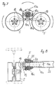
- a tracked vehicle 1 according to FIG. 1 has a tracked drive in the form of a Trapezoidal chain drive 2.
- the trapezoidal chain drive 2 is on everyone Drive side with one, rotating over several wheels 4 to 7 Provide chain 3. Both sides of the drive are identical.
- Each chain 3 is driven by a Turasrad 4.
- This Turasrad 4 on each side of the vehicle is connected to a drive hydraulics, which are not discussed in more detail here.
- the two drive wheels 4 on both sides of the vehicle - in the direction of travel seen - last wheel axle.
- the two chains 3 on both Six further wheel axles are assigned to the vehicle sides.
- the front wheel axle - seen in the direction of travel - is 3 for each chain each formed by a wheel 6, which is opposite to the axes of the wheels 5 and 7 shifted forward and upward relative to a traffic Is positioned underground. This results in an approximately trapezoidal one Circulation of each chain 3.
- the wheels 6, 7 on the two front wheel axles form in the following together described a tension pendulum.
- the four Impellers 5, the chain up to the Turasrad 4 in the contact area Chain 3, are paired to two running pendulums.
- FIGS. 2 to 6 The structure and function of the tension pendulum are shown in FIGS. 2 to 6 described in more detail below. Structure and function of the running pendulum are then described with reference to FIGS. 7 and 8.
- the wheels 6 and 7 of the front and the second front axle are each on a pendulum extension 11, 12 about an axis of rotation 8, 9 rotatably mounted.
- Each pendulum extension 11, 12 is a handlebar lever designed.
- Both pendulum processes 11, 12 are common Pivot axis 10 on a vehicle frame F (Fig. 6) can be pivoted stored.
- the distance of the axis of rotation 8 of the top and front Wheel 6 to the pivot axis 10 corresponds to approximately half the distance the axis of rotation 9 of the lower and rear wheel 7 of the Pivot axis 10. Accordingly, the pendulum extension 11 has approximately that half the length of the pendulum process 12.
- the short pendulum process 11 is freely pivotable about the pivot axis 10 according to FIG. 6.
- the lower Pendulum extension 12 is fixed, in particular by welding inner polygonal profile 16 of a pivot bearing of both pendulum extensions 11, 12 connected.
- the polygonal profile in the form of a Square profile, is in a polygonal hollow profile, present in one Square hollow profile integrated, the inner polygonal profile 16 in the outer hollow profile 17 with the help of cross section in the pressed state approximately triangular-shaped elastomer bodies 18 in a 45 ° to Hollow section 17 is held twisted position.
- the outer hollow profile 17th is positively secured to the frame by means of a holding flange 14, with the vehicle frame F, in the present case by screwing connected is.
- the four elastomer bodies 18 provide restoring means for the pendulum process 12 represents the pendulum process in an unloaded, static rest position hold and with a rotation of the pendulum extension 12 to the pivot axis 10 to this a restoring moment towards static Exercise rest position.
- the two wheels 6, 7 act as a common tension pendulum.
- This is a rigid connection between the pendulum extensions 11, 12 is provided, which are formed by a clamping means in the form of a linear actuator 13 is.
- the linear actuator 13 has one end in the region of the lower one Pendulum process 12 and with its other, inner end articulated in the region of a flange of the upper pendulum extension 11.
- the linear actuator 13 is designed as a threaded spindle.
- the lower wheel 7 serves as an impeller.
- the upper wheel 6 serves as a tensioning wheel.
- the chain tension of the chain 3 can be adjusted relative to one another.
- the impeller 7 of the tension pendulum in or out. 3 is the static state of the chain drive, in which the tension pendulum through the elastomer body 18 held in its unloaded rest position is. 2, the front impeller 7 is rebounded downwards. 4 it is compressed upwards.
- the tensioning wheel 6 tensions the chain 3 by appropriate rotation of the linear actuator 13, which serves as clamping kinematics. After this Tensioning the chain 3 form the pendulum extensions 11 and 12 together with the linear actuator 13 a rigid unit, so that the common Pendulum is formed.
- Overload protection is provided in a manner not shown in detail, which as a pressure relief valve in a hydraulic linear actuator 13 or designed as spring protection in the area of the swivel bearing can be.
- both impellers are also with the barrel pendulum 5 rotatably mounted on a pendulum extension 19.
- Pendulum extensions 19 are identical, so that the axes of rotation of the two wheels 5 the same distance from a pivot axis 10a.
- the axes of rotation form the two impellers 5 and the central pivot bearing 10a isosceles Triangle, as can be seen from FIG. 7.
- Both pendulum processes 19 are on the chassis frame on the vehicle side about the pivot axis 10a F pivoted.
- the two pendulum processes 19 are in the area of the pivot bearing by elastic return means in connection with each other.
- One pendulum extension 19 is fixed with an inner polygonal profile 16a and the other pendulum extension 19 firmly connected to an outer polygonal profile 17a.
- the two profiles 16a and 17a are designed analogously to the previously described tension pendulum.
- In the space between the inner polygonal profile 16a and the outer hollow profile 17a are four elastomeric bodies 18a as restoring means positioned the elastomeric bodies 18 of the tension pendulum 5 and 6 correspond.
- both impellers 5 are mounted so that they swing there is a wheel load balance between the oscillating ones Impellers 5 results.
- the two form through the elastomer body 18a Pendulum extensions 19 in the static state a stable unit, so that both wheels 5 around the pivot axis 10a as a common running pendulum are oscillating. It is also essentially vertical Compression and rebound possible by the two pendulum extensions 19 be deflected from its static state. Spread preferably the pendulum extensions 19 are relative to each other when appropriate Charges.
- the barrel pendulum can thus on the one hand around the pivot axis Rock 10a and on the other in or up rebound.
- the tracked vehicle according to the invention is particularly suitable for a Street legal.
Landscapes
- Engineering & Computer Science (AREA)
- Chemical & Material Sciences (AREA)
- Combustion & Propulsion (AREA)
- Transportation (AREA)
- Mechanical Engineering (AREA)
- Vehicle Body Suspensions (AREA)
- Motorcycle And Bicycle Frame (AREA)
Applications Claiming Priority (2)
| Application Number | Priority Date | Filing Date | Title |
|---|---|---|---|
| DE10160918 | 2001-12-07 | ||
| DE10160918A DE10160918B4 (de) | 2001-12-07 | 2001-12-07 | Kettenlaufwerk für ein Kettenfahrzeug |
Publications (2)
| Publication Number | Publication Date |
|---|---|
| EP1318067A2 true EP1318067A2 (fr) | 2003-06-11 |
| EP1318067A3 EP1318067A3 (fr) | 2004-03-03 |
Family
ID=7708862
Family Applications (1)
| Application Number | Title | Priority Date | Filing Date |
|---|---|---|---|
| EP02025762A Withdrawn EP1318067A3 (fr) | 2001-12-07 | 2002-11-16 | Chenille pour véhicule à chenilles |
Country Status (5)
| Country | Link |
|---|---|
| US (1) | US20050087374A1 (fr) |
| EP (1) | EP1318067A3 (fr) |
| CA (1) | CA2413900A1 (fr) |
| DE (1) | DE10160918B4 (fr) |
| NO (1) | NO20025767L (fr) |
Cited By (5)
| Publication number | Priority date | Publication date | Assignee | Title |
|---|---|---|---|---|
| EP3222500A1 (fr) | 2016-03-24 | 2017-09-27 | Kässbohrer Geländefahrzeug AG | Vehicule a chenilles et vehicule a chenilles civil |
| IT201600081206A1 (it) * | 2016-08-02 | 2018-02-02 | Cnh Ind Italia Spa | Sistema di cingolo per veicolo da lavoro |
| IT201600081200A1 (it) * | 2016-08-02 | 2018-02-02 | Cnh Ind Italia Spa | Sistema di cingolo per veicolo da lavoro |
| CN110723228A (zh) * | 2019-10-31 | 2020-01-24 | 万宝矿产有限公司 | 一种处理工程机械履带行走机构支撑轮脱链的方法 |
| EP3759014B1 (fr) | 2018-03-02 | 2023-11-01 | PRINOTH S.p.A. | Véhicule à chenilles pour la préparation de pistes de ski |
Families Citing this family (8)
| Publication number | Priority date | Publication date | Assignee | Title |
|---|---|---|---|---|
| US8083242B2 (en) * | 2007-02-15 | 2011-12-27 | Glen Brazier | Multi-pivot vehicle suspension |
| US8540040B2 (en) * | 2007-11-07 | 2013-09-24 | Gse Technologies, Llc | Multi-purpose ground vehicle |
| RU2544903C2 (ru) * | 2013-07-08 | 2015-03-20 | Евгений Николаевич Хрусталёв | Способ повышения проходимости движителя военной техники и устройство движителя военной техники |
| EP3205563B1 (fr) * | 2016-02-11 | 2021-07-07 | Kässbohrer Geländefahrzeug AG | Dameur de piste destine a entretenir et modeler les pistes de ski |
| IT201600081211A1 (it) * | 2016-08-02 | 2018-02-02 | Cnh Ind Italia Spa | Sistema di cingolo per veicolo da lavoro |
| EP3450225A1 (fr) * | 2017-09-04 | 2019-03-06 | BAE SYSTEMS plc | Système de suspension |
| WO2019043361A1 (fr) * | 2017-09-04 | 2019-03-07 | Bae Systems Plc | Système de suspension |
| CN110329375B (zh) * | 2019-07-04 | 2024-04-30 | 中国人民解放军陆军装甲兵学院 | 履带型摆臂悬挂式行走机构及履带车辆 |
Family Cites Families (18)
| Publication number | Priority date | Publication date | Assignee | Title |
|---|---|---|---|---|
| US1429589A (en) * | 1920-04-23 | 1922-09-19 | Helm Emil | Traction device for vehicles |
| US1580120A (en) * | 1925-04-17 | 1926-04-13 | Vickers Ltd | Endless-track vehicle |
| US2162198A (en) * | 1937-03-25 | 1939-06-13 | Marmon Herrington Co Inc | Continuous-track tractor |
| US2149297A (en) * | 1937-09-20 | 1939-03-07 | Harry A Knox | Suspension for vehicles |
| DE1925325A1 (de) * | 1969-05-19 | 1970-11-26 | Kober Kg A | Laufwerk fuer mit Raupen versehene Fahrzeuge |
| US3706481A (en) * | 1970-05-15 | 1972-12-19 | Goodrich Co B F | Vehicle suspension |
| US3799625A (en) * | 1972-06-12 | 1974-03-26 | R Statz | Suspension system for snow vehicle |
| US3938605A (en) * | 1974-06-24 | 1976-02-17 | Clark Equipment Company | Track suspension |
| US4279318A (en) * | 1978-05-26 | 1981-07-21 | Caterpillar Tractor Co. | Track tensioning apparatus |
| JPS598588B2 (ja) * | 1979-05-11 | 1984-02-25 | 株式会社小松製作所 | 装軌式車両の下転輪「県」架装置 |
| FR2636908A1 (fr) * | 1988-09-27 | 1990-03-30 | Armef | Engin automoteur a train chenille souple |
| NO175048B (no) * | 1992-06-15 | 1994-05-16 | Thor Reidar Froelich Braathen | Anordning ved terrenggående motorkjöretöy |
| US5340205A (en) * | 1992-11-13 | 1994-08-23 | Deere & Company | Suspension system for a tracked vehicle |
| DE4335657A1 (de) * | 1993-10-14 | 1995-04-20 | Claas Ohg | Gleiskettenlaufwerk |
| US5718445A (en) * | 1994-08-24 | 1998-02-17 | Suspensions, Inc. | Vehicle suspension system |
| US5842757A (en) * | 1997-01-31 | 1998-12-01 | Agtracks, Inc. | Track system for vehicles |
| US6247547B1 (en) * | 1998-04-21 | 2001-06-19 | A.S.V., Inc. | Suspension and drive mechanism for a multi-surface vehicle |
| JP3598089B2 (ja) * | 2001-10-22 | 2004-12-08 | 住友ゴム工業株式会社 | クローラ走行装置の転輪支持構造 |
-
2001
- 2001-12-07 DE DE10160918A patent/DE10160918B4/de not_active Expired - Fee Related
-
2002
- 2002-11-16 EP EP02025762A patent/EP1318067A3/fr not_active Withdrawn
- 2002-11-29 NO NO20025767A patent/NO20025767L/no unknown
- 2002-12-05 US US10/310,706 patent/US20050087374A1/en not_active Abandoned
- 2002-12-06 CA CA002413900A patent/CA2413900A1/fr not_active Abandoned
Non-Patent Citations (1)
| Title |
|---|
| None |
Cited By (8)
| Publication number | Priority date | Publication date | Assignee | Title |
|---|---|---|---|---|
| EP3222500A1 (fr) | 2016-03-24 | 2017-09-27 | Kässbohrer Geländefahrzeug AG | Vehicule a chenilles et vehicule a chenilles civil |
| RU2681821C2 (ru) * | 2016-03-24 | 2019-03-12 | Кессборер Гелендефарцойг АГ | Гусеничное транспортное средство гражданского назначения |
| IT201600081206A1 (it) * | 2016-08-02 | 2018-02-02 | Cnh Ind Italia Spa | Sistema di cingolo per veicolo da lavoro |
| IT201600081200A1 (it) * | 2016-08-02 | 2018-02-02 | Cnh Ind Italia Spa | Sistema di cingolo per veicolo da lavoro |
| WO2018024762A3 (fr) * | 2016-08-02 | 2018-03-15 | Cnh Industrial Italia S.P.A. | Système de chenilles pour engin de chantier |
| WO2018024758A3 (fr) * | 2016-08-02 | 2018-03-22 | Cnh Industrial Italia S.P.A. | Système de chenilles pour engin de chantier |
| EP3759014B1 (fr) | 2018-03-02 | 2023-11-01 | PRINOTH S.p.A. | Véhicule à chenilles pour la préparation de pistes de ski |
| CN110723228A (zh) * | 2019-10-31 | 2020-01-24 | 万宝矿产有限公司 | 一种处理工程机械履带行走机构支撑轮脱链的方法 |
Also Published As
| Publication number | Publication date |
|---|---|
| US20050087374A1 (en) | 2005-04-28 |
| DE10160918A1 (de) | 2003-06-26 |
| NO20025767L (no) | 2003-06-10 |
| DE10160918B4 (de) | 2009-03-05 |
| EP1318067A3 (fr) | 2004-03-03 |
| NO20025767D0 (no) | 2002-11-29 |
| CA2413900A1 (fr) | 2003-06-07 |
Similar Documents
| Publication | Publication Date | Title |
|---|---|---|
| EP1911716B1 (fr) | Grue | |
| DE69300838T3 (de) | Vorrichtung zur Lenkung von Hinterrädern. | |
| DE4213105C2 (de) | Vorderradaufhängung für Kraftfahrzeuge, insbesondere Autobusse | |
| EP1318067A2 (fr) | Chenille pour véhicule à chenilles | |
| DE60222357T2 (de) | Laufrollenträger für eine Gleisketteneinheit | |
| DE3232410A1 (de) | Radaufhaengung fuer fahrzeuge | |
| DE1630094A1 (de) | Hoehenverstellbares Leitrad fuer Gleiskettenfahrzeuge | |
| WO2018054694A1 (fr) | Fauteuil roulant | |
| EP3339147B1 (fr) | Appareil de roulement à chenilles | |
| DE2658932B2 (de) | Zentralgelenk für ein selbstfahrendes, gelenktes Fahrzeug | |
| EP0678443B1 (fr) | Train de roulement, notamment pour machines de travail mobiles et véhicules | |
| DE1530023A1 (de) | Fahrzeug | |
| EP0562598A1 (fr) | Assemblage à rotule entre deux véhicules articulés | |
| EP3222500A1 (fr) | Vehicule a chenilles et vehicule a chenilles civil | |
| DE202011102504U1 (de) | Selbstfahrende Arbeitsmaschine mit einem Kettenlaufwerk | |
| WO2021254646A1 (fr) | Véhicule utilitaire militaire | |
| DE4231323A1 (de) | Elastische Verbindung zwischen Vorderwagen und Hinterwagen eines Straßengelenkfahrzeugs | |
| DE1171755B (de) | Raupenrad fuer Kraftfahrzeuge, insbesondere Ackerschlepper | |
| DE3028007C2 (de) | Knickgelenktes Fahrzeug | |
| DE2123743C3 (de) | Federung für Fahrzeuge, insbesondere Lastkraftwagen | |
| EP1221399B1 (fr) | Système d' hayon élévateur | |
| DE2851880A1 (de) | Fahrzeug | |
| DE102014006774A1 (de) | Fahrmischer für fließfähige Medien, insbesondere Beton | |
| DE2642902A1 (de) | Lenkachse fuer ein flurfoerderzeug | |
| EP4275927A1 (fr) | Véhicule |
Legal Events
| Date | Code | Title | Description |
|---|---|---|---|
| PUAI | Public reference made under article 153(3) epc to a published international application that has entered the european phase |
Free format text: ORIGINAL CODE: 0009012 |
|
| AK | Designated contracting states |
Designated state(s): AT BE BG CH CY CZ DE DK EE ES FI FR GB GR IE IT LI LU MC NL PT SE SK TR |
|
| AX | Request for extension of the european patent |
Extension state: AL LT LV MK RO SI |
|
| PUAL | Search report despatched |
Free format text: ORIGINAL CODE: 0009013 |
|
| AK | Designated contracting states |
Kind code of ref document: A3 Designated state(s): AT BE BG CH CY CZ DE DK EE ES FI FR GB GR IE IT LI LU MC NL PT SE SK TR |
|
| AX | Request for extension of the european patent |
Extension state: AL LT LV MK RO SI |
|
| RIC1 | Information provided on ipc code assigned before grant |
Ipc: 7B 60G 5/06 B Ipc: 7B 60G 21/055 B Ipc: 7B 62D 55/108 B Ipc: 7B 62D 55/30 A |
|
| 17P | Request for examination filed |
Effective date: 20040323 |
|
| AKX | Designation fees paid |
Designated state(s): AT CH DE FR IT LI |
|
| STAA | Information on the status of an ep patent application or granted ep patent |
Free format text: STATUS: THE APPLICATION IS DEEMED TO BE WITHDRAWN |
|
| 18D | Application deemed to be withdrawn |
Effective date: 20060111 |