EP1319528A2 - Bandage pneumatique asymétrique pour véhicules - Google Patents
Bandage pneumatique asymétrique pour véhicules Download PDFInfo
- Publication number
- EP1319528A2 EP1319528A2 EP02027600A EP02027600A EP1319528A2 EP 1319528 A2 EP1319528 A2 EP 1319528A2 EP 02027600 A EP02027600 A EP 02027600A EP 02027600 A EP02027600 A EP 02027600A EP 1319528 A2 EP1319528 A2 EP 1319528A2
- Authority
- EP
- European Patent Office
- Prior art keywords
- tire
- reinforcing layer
- reinforcing
- tread
- longitudinal groove
- Prior art date
- Legal status (The legal status is an assumption and is not a legal conclusion. Google has not performed a legal analysis and makes no representation as to the accuracy of the status listed.)
- Granted
Links
Images

Classifications
-
- B—PERFORMING OPERATIONS; TRANSPORTING
- B60—VEHICLES IN GENERAL
- B60C—VEHICLE TYRES; TYRE INFLATION; TYRE CHANGING; CONNECTING VALVES TO INFLATABLE ELASTIC BODIES IN GENERAL; DEVICES OR ARRANGEMENTS RELATED TO TYRES
- B60C11/00—Tyre tread bands; Tread patterns; Anti-skid inserts
- B60C11/03—Tread patterns
- B60C11/0304—Asymmetric patterns
-
- B—PERFORMING OPERATIONS; TRANSPORTING
- B60—VEHICLES IN GENERAL
- B60C—VEHICLE TYRES; TYRE INFLATION; TYRE CHANGING; CONNECTING VALVES TO INFLATABLE ELASTIC BODIES IN GENERAL; DEVICES OR ARRANGEMENTS RELATED TO TYRES
- B60C19/00—Tyre parts or constructions not otherwise provided for
- B60C19/001—Tyres requiring an asymmetric or a special mounting
-
- B—PERFORMING OPERATIONS; TRANSPORTING
- B60—VEHICLES IN GENERAL
- B60C—VEHICLE TYRES; TYRE INFLATION; TYRE CHANGING; CONNECTING VALVES TO INFLATABLE ELASTIC BODIES IN GENERAL; DEVICES OR ARRANGEMENTS RELATED TO TYRES
- B60C3/00—Tyres characterised by the transverse section
- B60C3/06—Tyres characterised by the transverse section asymmetric
-
- B—PERFORMING OPERATIONS; TRANSPORTING
- B60—VEHICLES IN GENERAL
- B60C—VEHICLE TYRES; TYRE INFLATION; TYRE CHANGING; CONNECTING VALVES TO INFLATABLE ELASTIC BODIES IN GENERAL; DEVICES OR ARRANGEMENTS RELATED TO TYRES
- B60C9/00—Reinforcements or ply arrangement of pneumatic tyres
- B60C9/18—Structure or arrangement of belts or breakers, crown-reinforcing or cushioning layers
- B60C9/30—Structure or arrangement of belts or breakers, crown-reinforcing or cushioning layers asymmetric to the midcircumferential plane of the tyre
Definitions
- the present invention relates to a vehicle tire.
- the present invention relates to a vehicle tire of the type comprising a toroidal radial carcass having an equatorial plane, a tread, and an annular tread belt interposed between the tread and the carcass and divided by said equatorial plane into an outer annular portion and an inner annular portion; said tread comprising an outer shoulder and an inner shoulder, and having at least a first outer longitudinal groove adjacent to said outer shoulder, and at least a first inner longitudinal groove adjacent to said inner shoulder; and said annular tread belt having a first lateral edge located at said outer shoulder, and a second lateral edge located at said inner shoulder.
- the present invention is particularly advantageous in the case of high-performance tires, normally mounted with a positive camber angle, to which the following description refers purely by way of example.
- annular tread belts are used to impart to the tire a relatively high degree of stiffness.
- Tires of this type when mounted with a positive camber angle, have several drawbacks by deforming poorly. That is, at least when traveling in a straight line, the ground-contact print is relatively small and only covers a portion of the tread width towards an inner shoulder of the tread, thus resulting in relatively severe specific ground pressure and heating, and poor thermal exchange with the ground.
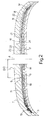
- Number 1 in Figure 1 indicates as a whole a vehicle tire, which is shown mounted on a rim 2 and comprises a toroidal radial carcass 3 having an equatorial plane 4 and, externally, a tread 5 and an annular tread belt 6 interposed between tread 5 and carcass 3.
- Tread 5 comprises an outer shoulder 7 and inner shoulder 8 defined, towards equatorial plane 4, by respective continuous or discontinuous longitudinal grooves 9 and 10, and has, in the central portion between longitudinal grooves 9 and 10, at least one longitudinal groove 11, also not necessarily continuous, located between equatorial plane 4 and longitudinal groove 9 and at a distance D from longitudinal groove 9, and at least one longitudinal groove 12, also not necessarily continuous, located between equatorial plane 4 and longitudinal groove 10.
- Annular tread belt 6 has a first lateral edge 13 at outer shoulder 7, and a second lateral edge 14 at inner shoulder 8; is divided by equatorial plane 4 into an outer annular portion 15 and an inner annular portion 16; and is defined by superimposed tread plies 17, which are two in number in the example shown, but which may, obviously, be more than two.
- a reinforcing layer 18 is interposed between outer annular portion 15 and tread 5, and is formed in known manner by winding, on outer annular portion 15 and about an axis (not shown) of tire 1, a continuous strip (not shown) of elastomeric material, preferably of the same type as that constituting the reinforcing material of tread plies 17.
- Reinforcing layer 18 covers lateral edge 13 of annular tread belt 6, extends towards equatorial plane 4 and beyond longitudinal groove 9, and has, on the side facing equatorial plane 4, an inner lateral edge 19 located between longitudinal grooves 9 and 11 and, preferably, at a distance from longitudinal groove 9 equal to less than half distance D.
- a reinforcing layer 20 is interposed between inner annular portion 16 and tread 5, and is formed in known manner by winding, on inner annular portion 16 and about an axis (not shown) of tire 1, a continuous strip (not shown) of elastomeric material, preferably of the same type as that constituting the reinforcing material of tread plies 17.
- Reinforcing layer 20 covers lateral edge 14 of annular tread belt 6, and has, on the side facing equatorial plane 4, an inner lateral edge 21 located between lateral edge 14 and longitudinal groove 10 and preferably at a distance of at least 5 mm from longitudinal groove 10.
- reinforcing layer 22 is formed by winding a strip (not shown) of elastomeric material about an axis (not shown) of tire 1, and extends radially outwards of reinforcing layer 18 and between annular tread belt 6 and reinforcing layer 20.
- reinforcing layers 18, 20 and 22 define a single annular reinforcing element 23 having a substantially S-shaped half-section, and are formed using a single strip (not shown) of elastomeric material, which is wound about annular tread belt 6 and the axis (not shown) of tire 1, first leftwards in Figure 1 from inner lateral edge 19 to form reinforcing layer 18, then rightwards in Figure 1 from lateral edge 13 to form reinforcing layer 22, and finally leftwards again in Figure 1 from lateral edge 14 to form reinforcing layer 20.
- a heat-conducting base 24 of known composition is interposed between annular reinforcing element 23 - in particular, reinforcing layer 20 - and tread 5, and covers at least the whole of inner annular portion 16 of annular tread belt 6. At most, heat-conducting base 24 may be extended, as in the example shown, to a part of outer annular portion 15 adjacent to equatorial plane 4, but, if so, always terminates short (in the example shown, just short) of longitudinal groove 9.
Landscapes
- Engineering & Computer Science (AREA)
- Mechanical Engineering (AREA)
- Tires In General (AREA)
- Transition And Organic Metals Composition Catalysts For Addition Polymerization (AREA)
- Arrangement Or Mounting Of Propulsion Units For Vehicles (AREA)
Applications Claiming Priority (2)
| Application Number | Priority Date | Filing Date | Title |
|---|---|---|---|
| ITTO20011155 | 2001-12-11 | ||
| IT2001TO001155A ITTO20011155A1 (it) | 2001-12-11 | 2001-12-11 | Pneumatico asimmetrico per autoveicoli. |
Publications (3)
| Publication Number | Publication Date |
|---|---|
| EP1319528A2 true EP1319528A2 (fr) | 2003-06-18 |
| EP1319528A3 EP1319528A3 (fr) | 2003-09-10 |
| EP1319528B1 EP1319528B1 (fr) | 2006-05-10 |
Family
ID=11459331
Family Applications (1)
| Application Number | Title | Priority Date | Filing Date |
|---|---|---|---|
| EP02027600A Expired - Lifetime EP1319528B1 (fr) | 2001-12-11 | 2002-12-10 | Bandage pneumatique asymétrique pour véhicules |
Country Status (7)
| Country | Link |
|---|---|
| EP (1) | EP1319528B1 (fr) |
| DE (1) | DE60211288T2 (fr) |
| ES (1) | ES2261587T3 (fr) |
| IT (1) | ITTO20011155A1 (fr) |
| PL (1) | PL208257B1 (fr) |
| PT (1) | PT1319528E (fr) |
| RU (1) | RU2293029C2 (fr) |
Families Citing this family (1)
| Publication number | Priority date | Publication date | Assignee | Title |
|---|---|---|---|---|
| PL404591A1 (pl) | 2013-07-08 | 2015-01-19 | Ryszard Gawerski | Opona pneumatyczna |
Family Cites Families (4)
| Publication number | Priority date | Publication date | Assignee | Title |
|---|---|---|---|---|
| FR1342822A (fr) * | 1962-09-03 | 1963-11-15 | Michelin & Cie | Perfectionnements aux enveloppes de pneumatiques |
| FR2184469B2 (fr) * | 1972-05-18 | 1974-12-20 | Uniroyal | |
| FR2215331B1 (fr) * | 1973-01-29 | 1976-05-14 | Kleber Colombes | |
| DE4240278A1 (de) * | 1992-12-01 | 1994-06-09 | Uniroyal Englebert Gmbh | Fahrzeugluftreifen mit asymmetrischen Gürteleigenschaften |
-
2001
- 2001-12-11 IT IT2001TO001155A patent/ITTO20011155A1/it unknown
-
2002
- 2002-12-10 ES ES02027600T patent/ES2261587T3/es not_active Expired - Lifetime
- 2002-12-10 EP EP02027600A patent/EP1319528B1/fr not_active Expired - Lifetime
- 2002-12-10 RU RU2002133411/11A patent/RU2293029C2/ru not_active IP Right Cessation
- 2002-12-10 PT PT02027600T patent/PT1319528E/pt unknown
- 2002-12-10 PL PL357658A patent/PL208257B1/pl unknown
- 2002-12-10 DE DE60211288T patent/DE60211288T2/de not_active Expired - Fee Related
Also Published As
| Publication number | Publication date |
|---|---|
| DE60211288D1 (de) | 2006-06-14 |
| ITTO20011155A0 (it) | 2001-12-11 |
| EP1319528A3 (fr) | 2003-09-10 |
| DE60211288T2 (de) | 2007-04-12 |
| ITTO20011155A1 (it) | 2003-06-11 |
| RU2293029C2 (ru) | 2007-02-10 |
| PL357658A1 (en) | 2003-06-16 |
| PL208257B1 (pl) | 2011-04-29 |
| EP1319528B1 (fr) | 2006-05-10 |
| PT1319528E (pt) | 2006-07-31 |
| ES2261587T3 (es) | 2006-11-16 |
Similar Documents
| Publication | Publication Date | Title |
|---|---|---|
| US5360043A (en) | Asymmetric tread for a tire | |
| US7036541B2 (en) | Pneumatic tire | |
| JP4015623B2 (ja) | 重荷重用タイヤ | |
| CN101772427B (zh) | 摩托车用轮胎及其制造方法 | |
| EP4313631B1 (fr) | Pneu à haute performance | |
| EP0066531B1 (fr) | Bande de roulement pour pneumatiques radiaux de poids lourds | |
| JP4817711B2 (ja) | 自動二輪車用空気入りラジアルタイヤ | |
| JPH07223407A (ja) | 空気入りラジアルタイヤ | |
| EP3231638B9 (fr) | Pneu | |
| US6564839B1 (en) | Pneumatic tire having a load dependent adaptive footprint shape | |
| JPH0684121B2 (ja) | 高速操縦安定性に優れる乗用車用ラジアルタイヤ | |
| US5529102A (en) | Motorcycle radial tire with supplementary breaker ply | |
| JP4257713B2 (ja) | 重荷重用空気入りラジアルタイヤ | |
| JPH069921B2 (ja) | 良路高速走行重荷重用ラジアルタイヤ | |
| JPH0781324A (ja) | 重荷重用タイヤ | |
| JP2004148954A (ja) | 空気入りタイヤおよびその装着方法 | |
| EP1319528B1 (fr) | Bandage pneumatique asymétrique pour véhicules | |
| JP4705284B2 (ja) | Atv用ラジアルタイヤ | |
| JPH03164305A (ja) | 乗用車用ラジアルタイヤ | |
| JPH08188015A (ja) | 車両用前後輪空気入りタイヤ対 | |
| EP0778162B1 (fr) | Pneumatique | |
| JPH06183209A (ja) | 重荷重用タイヤ | |
| JP4286588B2 (ja) | 空気入りタイヤ | |
| JP2007076594A (ja) | 空気入りタイヤ | |
| JP3863570B2 (ja) | 空気タイヤ |
Legal Events
| Date | Code | Title | Description |
|---|---|---|---|
| PUAI | Public reference made under article 153(3) epc to a published international application that has entered the european phase |
Free format text: ORIGINAL CODE: 0009012 |
|
| AK | Designated contracting states |
Designated state(s): AT BE BG CH CY CZ DE DK EE ES FI FR GB GR IE IT LI LU MC NL PT SE SI SK TR |
|
| AX | Request for extension of the european patent |
Extension state: AL LT LV MK RO |
|
| PUAL | Search report despatched |
Free format text: ORIGINAL CODE: 0009013 |
|
| AK | Designated contracting states |
Kind code of ref document: A3 Designated state(s): AT BE BG CH CY CZ DE DK EE ES FI FR GB GR IE IT LI LU MC NL PT SE SI SK TR |
|
| AX | Request for extension of the european patent |
Extension state: AL LT LV MK RO |
|
| 17P | Request for examination filed |
Effective date: 20040308 |
|
| AKX | Designation fees paid |
Designated state(s): DE ES FR GB PT |
|
| GRAP | Despatch of communication of intention to grant a patent |
Free format text: ORIGINAL CODE: EPIDOSNIGR1 |
|
| GRAS | Grant fee paid |
Free format text: ORIGINAL CODE: EPIDOSNIGR3 |
|
| RAP1 | Party data changed (applicant data changed or rights of an application transferred) |
Owner name: BRIDGESTONE TECHNICAL CENTER EUROPE S.P.A. |
|
| GRAA | (expected) grant |
Free format text: ORIGINAL CODE: 0009210 |
|
| AK | Designated contracting states |
Kind code of ref document: B1 Designated state(s): DE ES FR GB PT |
|
| REG | Reference to a national code |
Ref country code: GB Ref legal event code: FG4D |
|
| REF | Corresponds to: |
Ref document number: 60211288 Country of ref document: DE Date of ref document: 20060614 Kind code of ref document: P |
|
| REG | Reference to a national code |
Ref country code: PT Ref legal event code: SC4A Effective date: 20060522 |
|
| REG | Reference to a national code |
Ref country code: ES Ref legal event code: FG2A Ref document number: 2261587 Country of ref document: ES Kind code of ref document: T3 |
|
| ET | Fr: translation filed | ||
| PGFP | Annual fee paid to national office [announced via postgrant information from national office to epo] |
Ref country code: GB Payment date: 20070207 Year of fee payment: 5 |
|
| PLBE | No opposition filed within time limit |
Free format text: ORIGINAL CODE: 0009261 |
|
| STAA | Information on the status of an ep patent application or granted ep patent |
Free format text: STATUS: NO OPPOSITION FILED WITHIN TIME LIMIT |
|
| PGFP | Annual fee paid to national office [announced via postgrant information from national office to epo] |
Ref country code: PT Payment date: 20070411 Year of fee payment: 5 |
|
| PGFP | Annual fee paid to national office [announced via postgrant information from national office to epo] |
Ref country code: DE Payment date: 20070412 Year of fee payment: 5 Ref country code: ES Payment date: 20070412 Year of fee payment: 5 |
|
| 26N | No opposition filed |
Effective date: 20070213 |
|
| REG | Reference to a national code |
Ref country code: PT Ref legal event code: MM4A Free format text: LAPSE DUE TO NON-PAYMENT OF FEES Effective date: 20080611 |
|
| GBPC | Gb: european patent ceased through non-payment of renewal fee |
Effective date: 20071210 |
|
| PG25 | Lapsed in a contracting state [announced via postgrant information from national office to epo] |
Ref country code: PT Free format text: LAPSE BECAUSE OF NON-PAYMENT OF DUE FEES Effective date: 20080611 |
|
| PG25 | Lapsed in a contracting state [announced via postgrant information from national office to epo] |
Ref country code: DE Free format text: LAPSE BECAUSE OF NON-PAYMENT OF DUE FEES Effective date: 20080701 |
|
| REG | Reference to a national code |
Ref country code: FR Ref legal event code: ST Effective date: 20081020 |
|
| PG25 | Lapsed in a contracting state [announced via postgrant information from national office to epo] |
Ref country code: GB Free format text: LAPSE BECAUSE OF NON-PAYMENT OF DUE FEES Effective date: 20071210 |
|
| REG | Reference to a national code |
Ref country code: ES Ref legal event code: FD2A Effective date: 20071211 |
|
| PG25 | Lapsed in a contracting state [announced via postgrant information from national office to epo] |
Ref country code: FR Free format text: LAPSE BECAUSE OF NON-PAYMENT OF DUE FEES Effective date: 20071231 Ref country code: ES Free format text: LAPSE BECAUSE OF NON-PAYMENT OF DUE FEES Effective date: 20071211 |
|
| PG25 | Lapsed in a contracting state [announced via postgrant information from national office to epo] |
Ref country code: FR Free format text: LAPSE BECAUSE OF NON-PAYMENT OF DUE FEES Effective date: 20061231 |