EP1319626A1 - Aufzugssystem und inspektionsverfahren dafür - Google Patents
Aufzugssystem und inspektionsverfahren dafür Download PDFInfo
- Publication number
- EP1319626A1 EP1319626A1 EP00961120A EP00961120A EP1319626A1 EP 1319626 A1 EP1319626 A1 EP 1319626A1 EP 00961120 A EP00961120 A EP 00961120A EP 00961120 A EP00961120 A EP 00961120A EP 1319626 A1 EP1319626 A1 EP 1319626A1
- Authority
- EP
- European Patent Office
- Prior art keywords
- car
- elevator system
- landing
- hoist
- entrance
- Prior art date
- Legal status (The legal status is an assumption and is not a legal conclusion. Google has not performed a legal analysis and makes no representation as to the accuracy of the status listed.)
- Granted
Links
Images





Classifications
-
- B—PERFORMING OPERATIONS; TRANSPORTING
- B66—HOISTING; LIFTING; HAULING
- B66B—ELEVATORS; ESCALATORS OR MOVING WALKWAYS
- B66B5/00—Applications of checking, fault-correcting, or safety devices in elevators
- B66B5/0043—Devices enhancing safety during maintenance
- B66B5/005—Safety of maintenance personnel
-
- B—PERFORMING OPERATIONS; TRANSPORTING
- B66—HOISTING; LIFTING; HAULING
- B66B—ELEVATORS; ESCALATORS OR MOVING WALKWAYS
- B66B5/00—Applications of checking, fault-correcting, or safety devices in elevators
- B66B5/0087—Devices facilitating maintenance, repair or inspection tasks
Definitions
- the present invention relates to maintenance inspection of a so-called machine room-less elevator in which a hoist is disposed in an upper portion of an elevator hoistway and an elevator control apparatus is housed in the hoistway thus making a machine room unnecessary, and in particular, to an elevator system in which an inspector may simply and safely perform hoist maintenance inspection.
- FIG. 7 is a cross sectional drawing of a conventional machine room-less elevator system.
- a hoist 3 is disposed at a beam of an upper hoistway portion 1a of a hoistway 1 in which a car 2 of the elevator system is raised and lowered.
- the hoist 3, a control apparatus disposed inside the hoistway 1 and a control panel provided inside the car 2 are electrically connected, and the control apparatus outputs speed adjustment commands, stop commands and the like to safely and comfortably move the car 2 and perform driving control.
- the inspector 4 opens a closed door of an entrance 21 provided in a ceiling of the car 2 using a stepladder 11, and, from the entrance 21, he can then stand on a maintenance inspection scaffold 2a provided on a roof top of the car 2.
- the other inspector 4 raises/lowers the car 2 to a predetermined location from inside the car to facilitate maintenance inspection of the hoist 3 and maintenance inspection of the hoist 3 is performed.
- one goes out from the entrance 21 in the ceiling of the car 2 raises/lowers the car 2 and exits to the landing 10 outside the hoistway 1 from the door 6 of the car 2.
- the present invention aims to overcome these related problems and an object of the present invention is to provide, in a machine room-less elevator, an elevator system where there is no need to raise and lower a car when an inspector moves between a roof of a car and outside of a hoistway during maintenance inspection.
- Another object of the present invention is to provide an elevator system in which it is unnecessary to provide an entrance for access when doing maintenance inspection on the roof of the car.
- an elevator system comprising a hoist at an upper portion of a hoistway, and in which a car provided in the hoistway is raised and lowered by means of the hoist via a rope, wherein, stopping means which is operated during maintenance inspection of the hoist is provided for stopping the car at a predetermined location, and the predetermined location is a location where a roof top of the car is a predetermined amount lower than an upper frame of a landing entrance of a highest floor.
- an elevator system wherein, a step portion is provided at a freely opening and closing car-side door provided at an entrance of the car.
- an elevator system wherein, the step portion is housed in the car-side door during normal operation of the elevator system and forms a convex portion during maintenance inspection of the elevator system.
- an elevator system wherein, an entrance height of a landing of a highest floor is set to be a predetermined amount higher than an entrance height of the car.
- an elevator system wherein, a shielding plate is provided at an upper portion of the landing entrance and between the hoistway and a landing-side door provided at the landing entrance.
- a method of inspecting an elevator system wherein, in an elevator system comprising a hoist at an upper portion of a hoistway, and in which a car provided in the hoistway is raised and lowered by means of the hoist via a rope, a roof top of the car is raised from a position a floor face of a landing entrance of a highest floor, and the roof top of the car is stopped at a predetermined position lower than an upper frame of a landing entrance of the highest floor and maintenance inspection of the hoist is performed.
- FIG. 1 is a cross sectional drawing showing an elevator system according to Embodiment 1 of the present invention.
- a car 2 moves up and down in a hoistway 1 comprising an elevator system, and a scaffold 2a is provided at a roof of the car 2. Also, a rope 3a connected to the roof is hoisted by a hoist 3 to raise/lower the car 2.
- passengers may go in and out between an elevator landing 10 and the car 2 by opening and closing of a landing-side door 5 disposed at a landing entrance of the elevator so as to open and close freely and a car-side door provided at an entrance of the car 2 so as to open and close freely.
- a switch 7 for stopping the car 2 at a predetermined position is provided in the hoistway 1
- a cam 8 for contacting the switch 7 at the predetermined position and turning the switch 7 ON is provided on an external side portion of the car 2
- a control panel 9 for maintenance inspection operations and the like is disposed at the elevator landing 10 and a stepladder 11 is used for accessing the elevator landing 10 and a hoistway upper portion 1a.
- the hoist 3 is disposed at a beam of the hoistway upper portion 1a and is electrically connected with a control apparatus disposed in the hoistway and the control panel 9 disposed in the elevator landing.
- the control apparatus outputs speed adjustment commands, stop commands and the like to safely and comfortably move the car 2 and perform driving control.
- the cam 8 provided on a side portion of the car 2 is housed in the car 2 during normal operation of the elevator system so as to not contact the switch 7, and only during a maintenance inspection operation does it form a convex portion on the outside of the car 2 to contact the switch 7. That is, the switch 7 and cam 8 comprise a stopping means during a maintenance inspection operation.
- a stopping position of the car 2 stopped by means of the stopping means of the switch 7 and cam 8 is a position where an inspector 4 riding on the roof of the car 2 may easily perform maintenance inspection of the hoist 3 and is set such that there is a gap A (the A shown in FIG. 1) which allows the inspector 4 access between the roof of the car 2 and outside the hoistway 1.
- the gap A is a distance between the roof top of the car 2 and an upper portion of a frame (upper frame) comprising an entrance of the elevator landing 10 of a highest floor, and the roof top of the car 2 is stopped at a predetermined position lower than the upper frame of the entrance of the elevator landing 10. Since the car 2 is set so as to not rise above the stopping position during maintenance inspection of the hoist 3 by the stopping means, it is possible to insure the safety of the inspector 4 situated between the hoistway upper portion 1a and the roof top of the car 2 during the maintenance inspection.
- the inspector 4 operates a button and the like of the control panel 9 disposed at the elevator landing 10 of the highest floor of the building and operation of the elevator system is switched from normal operation to operation for maintenance inspection.
- maintenance inspection as performed by a number of inspectors 4 will be explained.
- the inspector 4 performs a maintenance inspection operation of the hoist 3 in a state where the car 2 is stopped at this predetermined position. In this case, once one wishes for some reason to go outside the hoistway 1 or in a case where the other inspector also participates in the operation, it is possible to have free access from the gap A connecting the elevator landing 10 and the roof of the car 2 using the stepladder 11 without raising/lowering the car 2.
- the maintenance inspection operation is finished and the inspector 4 operates a button and the like of the control panel 9 disposed at the elevator landing 10 of the highest floor of the building, the cam 8 is again housed in the car 2.
- the inspector(s) 4 may quickly evacuate to the elevator landing 10 outside the hoistway 1, and it is possible to easily alternate between the roof of the car 2 and outside the hoistway 1 (the elevator landing 10) during the maintenance inspection operation and the safety of the maintenance inspection operation may be increased.
- the stopping means comprises a mechanical means of the switch 7 and the cam 8
- a program for stopping at the predetermined position may also be loaded into the control apparatus of the elevator system in advance.
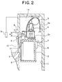
- FIG. 2 is a cross sectional drawing showing an elevator system according to Embodiment 2 of the present invention, and except for a step portion 12, all other points are similar to FIG. 1 which was explained in Embodiment 1. Thus, portions which are similar or correspond to those in Embodiment 1 will be assigned similar reference numerals and their explanation will be omitted.
- a step portion 12 is provided on an approximately central portion of the car-side door 6. Although the step portion 12 is housed flush with the door 6 during normal operation of the elevator system, it is provided so as to be capable of protruding during a maintenance inspection operation and the inspector 4 uses the step portion 12 for stepping when accessing the elevator landing 10 from the roof top of the car 2.
- the step portion 12 for the elevator system described in FIG. 2 is shown in FIG. 3 as viewed from the elevator landing 10. As shown in FIG.
- the step portion(s) 12 is provided on both sides of the biparting car-side door 6 and each portion protrudes during the maintenance inspection operation and the inspector 4, using these as footstool, is able to climb to the roof top of the car 2.
- step portion 12 is not limited as such and may also be provided on one side of the biparting car-side door 6 to be used footstool to climb to the roof top of the car 2.
- FIG. 4 is a cross sectional drawing showing an elevator system according to Embodiment 3 of the present invention, and although a height of an entrance of the elevator landing 10 to the car 2 differs, all other points are similar to FIG. 1 which was explained in Embodiment 1. Hence, portions which are similar or correspond to those in Embodiment 1 will be assigned similar reference numerals and their explanation will be omitted.
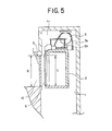
- FIG. 5 is a drawing showing the relationship between an entrance height of a landing of a normal elevator system and an entrance height of a car.
- an entrance height B of the elevator landing 10 and an entrance height C of the car are set so as to be approximately the same. That is to say, structures disposed on the upper portion of the roof of the car 2 are concealed when the landing-side door 5 of the elevator landing 10 is opened, and this improves an external appearance of the elevator system.
- shielding plate 13 is removably provided on an upper frame of the landing entrance and between the hoistway 1 and the landing-side door 5.
- the inspector 4 operates the control panel 9 provided at the highest floor of a building and switches operation of the elevator system from normal operation to operation for maintenance inspection and the landing-side door of the highest floor elevator landing 10 is opened. Then, the inspector 4 temporarily removes the shielding plate for inspection.
- the cam 8, housed in an external side surface of the car 2 during normal operation extends outside the side surface of the car 2.
- the control panel 9 to lower the car 2 so that the roof top of the car 2 and a floor face of highest floor landing are lined up, it is possible for an inspector 4 to get on the scaffold 2a provided on the roof top of the car 2.
- the cam 8 contacts the switch 7 and the switch 7 is turned ON and the car 2 stops at the predetermined position.
- FIG. 6 is a cross sectional drawing showing a gap between the upper frame of the landing entrance and the roof surface of the car 2.
- a gap A' is formed between the elevator landing entrance 10 and the roof of the car 2.
- the gap A' is a distance between the roof top of the car 2 and the upper frame of the entrance of the elevator landing 10 of the highest floor, and because a height of the upper frame of the entrance of the elevator landing is set higher than that in Embodiment 1, it is possible for the gap A' to have more clearance.
- the height of the entrance of the elevator landing 10 of the highest floor based on a position of the hoist 3, it is possible to freely adjust the distance between roof top of the car 2 and the upper frame of the entrance of the elevator landing 10 of the highest floor. Accordingly, one can easily alternate between the roof of the car 2 and outside the hoistway 1 (the elevator landing 10) during the maintenance inspection operation, the safety of the maintenance inspection operation may be increased and the efficiency of the maintenance inspection operation may also be improved.
- the elevator system of the present invention may be applied to a machine room-less elevator system comprising a hoist at an upper portion of a hoistway, and in which a car provided in the hoistway is raised and lowered by means of the hoist via a rope and wherein, stopping means, which is operated during maintenance inspection of the hoist, is provided for stopping the car at a predetermined location.
Landscapes
- Maintenance And Inspection Apparatuses For Elevators (AREA)
- Elevator Control (AREA)
- Cage And Drive Apparatuses For Elevators (AREA)
Applications Claiming Priority (1)
| Application Number | Priority Date | Filing Date | Title |
|---|---|---|---|
| PCT/JP2000/006421 WO2002024565A1 (en) | 2000-09-20 | 2000-09-20 | Elevator system and method of inspecting the elevator system |
Publications (3)
| Publication Number | Publication Date |
|---|---|
| EP1319626A1 true EP1319626A1 (de) | 2003-06-18 |
| EP1319626A4 EP1319626A4 (de) | 2006-06-07 |
| EP1319626B1 EP1319626B1 (de) | 2008-10-08 |
Family
ID=11736475
Family Applications (1)
| Application Number | Title | Priority Date | Filing Date |
|---|---|---|---|
| EP00961120A Expired - Lifetime EP1319626B1 (de) | 2000-09-20 | 2000-09-20 | Aufzugssystem und inspektionsverfahren dafür |
Country Status (4)
| Country | Link |
|---|---|
| EP (1) | EP1319626B1 (de) |
| JP (1) | JP4661022B2 (de) |
| DE (1) | DE60040489D1 (de) |
| WO (1) | WO2002024565A1 (de) |
Cited By (6)
| Publication number | Priority date | Publication date | Assignee | Title |
|---|---|---|---|---|
| EP1518815A1 (de) * | 2003-09-29 | 2005-03-30 | Inventio Ag | Türrahmen einer Schachttüre mit einer Kontrollanordnung für Aufzugsanlage und Verfahren zum Zugriff auf eine Kontrolleinheit |
| WO2008004022A1 (en) * | 2006-06-30 | 2008-01-10 | Otis Elevator Company | Elevator having a shallow pit and/or a low overhead |
| US8136637B2 (en) | 2006-06-30 | 2012-03-20 | Otis Elevator Company | Safety device for securing minimum spaces at the top or bottom of an elevator shaft being inspected, and elevator having such safety devices |
| US8746412B2 (en) | 2008-12-19 | 2014-06-10 | Otis Elevator Company | Elevator door frame with electronics housing |
| US8875845B2 (en) * | 2005-10-21 | 2014-11-04 | Alimak Ab | Safety arrangement for a lift car in a lift |
| CN106185522A (zh) * | 2016-08-19 | 2016-12-07 | 卢碧娴 | 电梯上的逃生装置 |
Families Citing this family (3)
| Publication number | Priority date | Publication date | Assignee | Title |
|---|---|---|---|---|
| ES2341070B1 (es) * | 2008-05-28 | 2011-06-10 | Orona, S.Coop. | Aparato elevador. |
| JP5586350B2 (ja) * | 2010-07-12 | 2014-09-10 | 三菱電機ビルテクノサービス株式会社 | エレベータのかご上保守作業用治具 |
| JP6521184B1 (ja) * | 2018-01-26 | 2019-05-29 | 三菱電機ビルテクノサービス株式会社 | エレベーターのかごの位置を作業に適する位置に維持する機能を備えた制御装置およびエレベーターシステム |
Citations (4)
| Publication number | Priority date | Publication date | Assignee | Title |
|---|---|---|---|---|
| JPH0597357A (ja) | 1991-10-04 | 1993-04-20 | Mitsubishi Electric Corp | エレベーターかご装置 |
| JPH06278973A (ja) | 1993-03-30 | 1994-10-04 | Mitsubishi Electric Corp | エレベータのかご室天井装置 |
| JPH09263372A (ja) | 1996-03-28 | 1997-10-07 | Mitsubishi Denki Bill Techno Service Kk | エレベータかご天井昇降装置 |
| EP1052212A1 (de) | 1999-05-14 | 2000-11-15 | Inventio Ag | Einrichtung zur Ausführung von Arbeiten in einem Aufzugsschacht |
Family Cites Families (6)
| Publication number | Priority date | Publication date | Assignee | Title |
|---|---|---|---|---|
| JPS6296285A (ja) * | 1985-10-21 | 1987-05-02 | 株式会社東芝 | エレベ−タの安全装置 |
| JP3438697B2 (ja) * | 1993-04-05 | 2003-08-18 | 三菱電機株式会社 | 機械室レスエレベータ装置 |
| FI98210C (fi) * | 1993-06-28 | 1997-05-12 | Kone Oy | Järjestely hissikoneiston liittämiseksi rakennukseen |
| ES2197280T3 (es) * | 1996-11-11 | 2004-01-01 | Inventio Ag | Instalacion de ascensor con una unidad de accionamiento dispuesta en la caja de ascensor. |
| JP2000086104A (ja) * | 1998-09-10 | 2000-03-28 | Toshiba Elevator Co Ltd | 機械室レスエレベータの点検運転装置 |
| US6691833B1 (en) * | 1999-02-05 | 2004-02-17 | Inventio Ag | Elevator without a machine room |
-
2000
- 2000-09-20 JP JP2002528589A patent/JP4661022B2/ja not_active Expired - Fee Related
- 2000-09-20 WO PCT/JP2000/006421 patent/WO2002024565A1/ja not_active Ceased
- 2000-09-20 DE DE60040489T patent/DE60040489D1/de not_active Expired - Lifetime
- 2000-09-20 EP EP00961120A patent/EP1319626B1/de not_active Expired - Lifetime
Patent Citations (4)
| Publication number | Priority date | Publication date | Assignee | Title |
|---|---|---|---|---|
| JPH0597357A (ja) | 1991-10-04 | 1993-04-20 | Mitsubishi Electric Corp | エレベーターかご装置 |
| JPH06278973A (ja) | 1993-03-30 | 1994-10-04 | Mitsubishi Electric Corp | エレベータのかご室天井装置 |
| JPH09263372A (ja) | 1996-03-28 | 1997-10-07 | Mitsubishi Denki Bill Techno Service Kk | エレベータかご天井昇降装置 |
| EP1052212A1 (de) | 1999-05-14 | 2000-11-15 | Inventio Ag | Einrichtung zur Ausführung von Arbeiten in einem Aufzugsschacht |
Non-Patent Citations (1)
| Title |
|---|
| See also references of WO0224565A1 |
Cited By (11)
| Publication number | Priority date | Publication date | Assignee | Title |
|---|---|---|---|---|
| EP1518815A1 (de) * | 2003-09-29 | 2005-03-30 | Inventio Ag | Türrahmen einer Schachttüre mit einer Kontrollanordnung für Aufzugsanlage und Verfahren zum Zugriff auf eine Kontrolleinheit |
| US7114594B2 (en) | 2003-09-29 | 2006-10-03 | Inventio AG | Door frame of a shaft door with a control arrangement for an elevator shaft and method for access to a control unit |
| CN1329275C (zh) * | 2003-09-29 | 2007-08-01 | 因温特奥股份公司 | 具有电梯设备控制装置的竖井门框和接触控制单元的方法 |
| US8875845B2 (en) * | 2005-10-21 | 2014-11-04 | Alimak Ab | Safety arrangement for a lift car in a lift |
| WO2008004022A1 (en) * | 2006-06-30 | 2008-01-10 | Otis Elevator Company | Elevator having a shallow pit and/or a low overhead |
| US8136637B2 (en) | 2006-06-30 | 2012-03-20 | Otis Elevator Company | Safety device for securing minimum spaces at the top or bottom of an elevator shaft being inspected, and elevator having such safety devices |
| US8162108B2 (en) | 2006-06-30 | 2012-04-24 | Otis Elevator Company | Elevator having a limit switch for controlling power to the drive system as an elevator car approaches a shallow pit or a low overhead |
| US8365870B2 (en) | 2006-06-30 | 2013-02-05 | Otis Elevator Company | Foldable handrail and safety switch arrangement on top of an elevator car |
| CN101472830B (zh) * | 2006-06-30 | 2013-07-17 | 奥蒂斯电梯公司 | 具有浅井坑和/或低顶盖的电梯 |
| US8746412B2 (en) | 2008-12-19 | 2014-06-10 | Otis Elevator Company | Elevator door frame with electronics housing |
| CN106185522A (zh) * | 2016-08-19 | 2016-12-07 | 卢碧娴 | 电梯上的逃生装置 |
Also Published As
| Publication number | Publication date |
|---|---|
| DE60040489D1 (de) | 2008-11-20 |
| EP1319626A4 (de) | 2006-06-07 |
| JP4661022B2 (ja) | 2011-03-30 |
| EP1319626B1 (de) | 2008-10-08 |
| WO2002024565A1 (en) | 2002-03-28 |
| JPWO2002024565A1 (ja) | 2004-01-29 |
Similar Documents
| Publication | Publication Date | Title |
|---|---|---|
| RU2478556C2 (ru) | Схема возврата в исходное состояние предохранительной цепи лифта | |
| JP2001080836A (ja) | 昇降路の出入りにおける安全性確保の方法及びエレベータ装置 | |
| EP1319626B1 (de) | Aufzugssystem und inspektionsverfahren dafür | |
| JP5268480B2 (ja) | エレベータ式駐車装置 | |
| JP2006199404A (ja) | エレベータの終端安全装置 | |
| JP4919593B2 (ja) | エレベータの運転装置 | |
| KR20010022972A (ko) | 엘리베이터 장치 | |
| JP4303830B2 (ja) | エレベーター装置 | |
| JP2006044889A (ja) | 避難用エレベータ装置 | |
| JP3953105B2 (ja) | 水平方向に移送されたエレベータかごを用いるエレベータシャトル | |
| JPH08301545A (ja) | エレベータの地震時管制運転装置 | |
| JP4251921B2 (ja) | エレベーター装置 | |
| JPH1111811A (ja) | エレベーター装置 | |
| JP2007031109A (ja) | エレベータ装置 | |
| JP2002096979A (ja) | エレベーター装置 | |
| JP7186638B2 (ja) | エレベーターのドアリオープン制御システム | |
| JP2001080834A (ja) | エレベータ装置及びそのエレベータ制御装置の保守点検方法 | |
| EP1329410B1 (de) | Aufzug und bestätigungsvorrichtung für die kabinestellung des aufzugs | |
| US20250145412A1 (en) | Elevator safety system | |
| JPH04223985A (ja) | ダブルデッキエレべータの運転方法 | |
| JP7616330B1 (ja) | エレベーター | |
| US20250145411A1 (en) | Elevator safety system | |
| KR20030021257A (ko) | 엘리베이터 장치 | |
| JP7754265B1 (ja) | エレベータ | |
| EP1571112A1 (de) | Aufzugsvorrichtung |
Legal Events
| Date | Code | Title | Description |
|---|---|---|---|
| PUAI | Public reference made under article 153(3) epc to a published international application that has entered the european phase |
Free format text: ORIGINAL CODE: 0009012 |
|
| 17P | Request for examination filed |
Effective date: 20020418 |
|
| AK | Designated contracting states |
Designated state(s): AT BE CH CY DE DK ES FI FR GB GR IE IT LI LU MC NL PT SE |
|
| RBV | Designated contracting states (corrected) |
Designated state(s): AT BE CH CY DE FR GB LI NL |
|
| RAP1 | Party data changed (applicant data changed or rights of an application transferred) |
Owner name: MITSUBISHI DENKI KABUSHIKI KAISHA |
|
| A4 | Supplementary search report drawn up and despatched |
Effective date: 20060508 |
|
| TPAC | Observations by third parties |
Free format text: ORIGINAL CODE: EPIDOSNTIPA |
|
| GRAP | Despatch of communication of intention to grant a patent |
Free format text: ORIGINAL CODE: EPIDOSNIGR1 |
|
| RBV | Designated contracting states (corrected) |
Designated state(s): DE FR GB NL |
|
| RIN1 | Information on inventor provided before grant (corrected) |
Inventor name: TAKIGAWA, YUKIHIRO,MITSUBISHI DENKI K. K. Inventor name: YOSHIKAWA, MASAMI,MITSUBISHI DENKI K. K. |
|
| GRAS | Grant fee paid |
Free format text: ORIGINAL CODE: EPIDOSNIGR3 |
|
| GRAA | (expected) grant |
Free format text: ORIGINAL CODE: 0009210 |
|
| AK | Designated contracting states |
Kind code of ref document: B1 Designated state(s): DE FR GB NL |
|
| REG | Reference to a national code |
Ref country code: GB Ref legal event code: FG4D |
|
| REF | Corresponds to: |
Ref document number: 60040489 Country of ref document: DE Date of ref document: 20081120 Kind code of ref document: P |
|
| PLBE | No opposition filed within time limit |
Free format text: ORIGINAL CODE: 0009261 |
|
| STAA | Information on the status of an ep patent application or granted ep patent |
Free format text: STATUS: NO OPPOSITION FILED WITHIN TIME LIMIT |
|
| 26N | No opposition filed |
Effective date: 20090709 |
|
| PGFP | Annual fee paid to national office [announced via postgrant information from national office to epo] |
Ref country code: FR Payment date: 20100921 Year of fee payment: 11 |
|
| PGFP | Annual fee paid to national office [announced via postgrant information from national office to epo] |
Ref country code: GB Payment date: 20100916 Year of fee payment: 11 |
|
| PGFP | Annual fee paid to national office [announced via postgrant information from national office to epo] |
Ref country code: NL Payment date: 20100916 Year of fee payment: 11 |
|
| PGFP | Annual fee paid to national office [announced via postgrant information from national office to epo] |
Ref country code: DE Payment date: 20100915 Year of fee payment: 11 |
|
| REG | Reference to a national code |
Ref country code: NL Ref legal event code: V1 Effective date: 20120401 |
|
| GBPC | Gb: european patent ceased through non-payment of renewal fee |
Effective date: 20110920 |
|
| REG | Reference to a national code |
Ref country code: FR Ref legal event code: ST Effective date: 20120531 |
|
| PG25 | Lapsed in a contracting state [announced via postgrant information from national office to epo] |
Ref country code: NL Free format text: LAPSE BECAUSE OF NON-PAYMENT OF DUE FEES Effective date: 20120401 |
|
| PG25 | Lapsed in a contracting state [announced via postgrant information from national office to epo] |
Ref country code: GB Free format text: LAPSE BECAUSE OF NON-PAYMENT OF DUE FEES Effective date: 20110920 Ref country code: FR Free format text: LAPSE BECAUSE OF NON-PAYMENT OF DUE FEES Effective date: 20110930 |
|
| PG25 | Lapsed in a contracting state [announced via postgrant information from national office to epo] |
Ref country code: DE Free format text: LAPSE BECAUSE OF NON-PAYMENT OF DUE FEES Effective date: 20130403 |
|
| REG | Reference to a national code |
Ref country code: DE Ref legal event code: R119 Ref document number: 60040489 Country of ref document: DE Effective date: 20130403 |