EP1320162B1 - Boîte de distribution en plastique montée au mur - Google Patents
Boîte de distribution en plastique montée au mur Download PDFInfo
- Publication number
- EP1320162B1 EP1320162B1 EP02022007.5A EP02022007A EP1320162B1 EP 1320162 B1 EP1320162 B1 EP 1320162B1 EP 02022007 A EP02022007 A EP 02022007A EP 1320162 B1 EP1320162 B1 EP 1320162B1
- Authority
- EP
- European Patent Office
- Prior art keywords
- box
- wall
- double
- distribution box
- wall mounted
- Prior art date
- Legal status (The legal status is an assumption and is not a legal conclusion. Google has not performed a legal analysis and makes no representation as to the accuracy of the status listed.)
- Expired - Lifetime
Links
- 238000009434 installation Methods 0.000 claims description 37
- 238000007789 sealing Methods 0.000 claims description 13
- 238000003780 insertion Methods 0.000 claims description 9
- 230000037431 insertion Effects 0.000 claims description 9
- 238000010616 electrical installation Methods 0.000 claims description 4
- 230000002093 peripheral effect Effects 0.000 description 3
- 238000009413 insulation Methods 0.000 description 2
- 238000005192 partition Methods 0.000 description 2
- 230000035515 penetration Effects 0.000 description 2
- 238000000926 separation method Methods 0.000 description 2
- 230000004913 activation Effects 0.000 description 1
- UVXCXZBZPFCAAJ-UHFFFAOYSA-N arc-111 Chemical compound C1=C2OCOC2=CC2=C(N(CCN(C)C)C(=O)C3=C4C=C(C(=C3)OC)OC)C4=CN=C21 UVXCXZBZPFCAAJ-UHFFFAOYSA-N 0.000 description 1
- 239000000969 carrier Substances 0.000 description 1
- 150000001875 compounds Chemical class 0.000 description 1
- 238000012423 maintenance Methods 0.000 description 1
- 238000004519 manufacturing process Methods 0.000 description 1
- 239000000463 material Substances 0.000 description 1
- 238000000034 method Methods 0.000 description 1
- 239000002689 soil Substances 0.000 description 1
- 230000007704 transition Effects 0.000 description 1
Images


Classifications
-
- H—ELECTRICITY
- H02—GENERATION; CONVERSION OR DISTRIBUTION OF ELECTRIC POWER
- H02G—INSTALLATION OF ELECTRIC CABLES OR LINES, OR OF COMBINED OPTICAL AND ELECTRIC CABLES OR LINES
- H02G3/00—Installations of electric cables or lines or protective tubing therefor in or on buildings, equivalent structures or vehicles
- H02G3/02—Details
- H02G3/08—Distribution boxes; Connection or junction boxes
- H02G3/12—Distribution boxes; Connection or junction boxes for flush mounting
- H02G3/121—Distribution boxes; Connection or junction boxes for flush mounting in plain walls
-
- H—ELECTRICITY
- H02—GENERATION; CONVERSION OR DISTRIBUTION OF ELECTRIC POWER
- H02G—INSTALLATION OF ELECTRIC CABLES OR LINES, OR OF COMBINED OPTICAL AND ELECTRIC CABLES OR LINES
- H02G3/00—Installations of electric cables or lines or protective tubing therefor in or on buildings, equivalent structures or vehicles
- H02G3/02—Details
- H02G3/08—Distribution boxes; Connection or junction boxes
- H02G3/12—Distribution boxes; Connection or junction boxes for flush mounting
- H02G3/123—Distribution boxes; Connection or junction boxes for flush mounting in thin walls
Definitions
- the invention relates to a hollow wall box made of plastic for electrical installations that can be used from the front in the breakthrough of a wall, the hollow wall box a Einstecktiefenbegrenzungs collar for flush insertion in the breakthrough and peripherally retaining surfaces or edges for interacting with the hole reveal the breakthrough in the Wall, as well as a hollow wall box final floor, the hollow wall box is formed as a top oval oval box with a can body, which is rounded in the region of the collar and the retaining surfaces or edges at its longitudinal ends semicircular, wherein the two semicircular shapes over straight Replacement side 1a
- connection areas are connected and the collar is provided radially projecting only in the region of the semicircular forms.
- a cavity wall socket known.
- Such hollow wall boxes are for electrical installations, such as For example, switches, sockets or the like useful.
- These hollow wall boxes can be used in a simple manner in the breakthrough of a cavity wall by a circular opening in the wall is created, in which the hollow cylindrical wall can be used in cross-section.
- the breakthrough is processed on the edge side with a peripheral counterbore, so that the Einstecktiefenbegrenzungskragen located at the mouth of the cavity wall socket sunk into the opening and the box is flush mounted in the opening.
- the corresponding screws are accessible from the front side of the box forth to press the retaining member back against the wall next to the breakthrough and so secure fit of the cavity wall socket.
- a sealing collar or a sealing body is arranged on the outside in the known hollow wall box, so that the hollow wall box can be inserted tightly into the corresponding opening or the like.
- the hollow wall box itself has a closed outer surface and a closed bottom, in which optionally breakable, cut or punched out openings for insertion of cables or the like can be set.
- the present invention seeks to provide a hollow wall box, which is suitable as a substitute for a double arrangement of individual cavity wall boxes and in which a largely windproof arrangement is made possible in a corresponding wall breakthrough.
- the retaining surfaces or edges are formed by a radially projecting surface area or edge region which surrounds the semicircular shape and the straight connection regions without interruption and in the form of sealing edges.
- the cavity wall box is designed as an oval double box, this is on the one hand, for example, for receiving two juxtaposed switches, sockets or the like suitable in the usual way can be fixed by means of support rings on the hollow wall box.
- To install the hollow wall box in a breakthrough of a wall it is only necessary to provide two circular openings in the wall, the center axes of which have a distance from each other, which correspond to the distance of the central axes of the pitch circles of the double box.
- the remaining between these holes permanent gusset can be removed in a simple manner manually or by means of a tool, so that the corresponding opening is also formed oval and the semicircles of the oval Wandungs trimbruches pass tangentially in a straight transition region.
- the oval double box can be used, so that the double box passes through the corresponding wall breakthrough largely windproof.
- the retaining surfaces or edges are formed by a radially projecting surface area or edge region that surrounds the semicircular shape and the straight connection regions without interruption.
- the double box on a can body which is rounded semicircular at least mündungsnah at its longitudinal ends, so that the end portions are formed by cylindrical portions in semicircular shape, which are connected via straight terminal areas, which also have parallel to the hole reveal extension.
- These areas should have at least such a height that the area extends over the entire height of the hole reveal. Whether and in how far the can on the other side of the hole reveal is tapered or has different shape is not decisive for the further state of affairs. It is only important that the Can in the immediate penetration area of the hole reveal this adapted shape and height. In this case, the semicircularly rounded portions at the mouth of the box radially outwardly projecting collar.
- a holding surface or retaining edge for example in Provided form of a rib, which rests in the installation target situation circumferentially at the hole reveal near the rear end in the insertion direction of the hole reveal, so that a tight arrangement of the double box is ensured in the corresponding recess.
- the intermediate wall completely separates the two installation places of the double box in the assembly target position used in the double box.
- an installation gap for performing electrical lines or the like installation means is formed between the intermediate wall and the bottom of the double box in assembly target position of the intermediate wall.
- the cavity wall box according to the invention is useful not only for the installation of two conventional installation devices, but it is also possible in the one installation space, for example, an electronic component, a transformer, a circuit arrangement or a to accommodate other electrical arrangement, which need not be accessible from the outside and which is, for example, in operative connection with the arranged on the other installation site installation part. In this case, it is necessary to cover the installation space in which no installation device such as switch or socket is arranged.
- a half-lid is provided, which is flush with the mouth of the double box and covers one of the two installation sites.
- the corresponding half-lid can alternatively be inserted over one of the two installation places, so that this installation place is covered.
- the half-lid can be covered with paper or be covered in any other way.
- notches and recesses is provided primarily in the area between the mouth edge and serving as a sealing surface or sealing edge retaining surfaces or retaining edges, so that the wind-tightness of the can is not affected by such recesses in total.
- the half-lid is formed as a trough-like molded part with a bottom and the floor abragendem, circumferential collar
- the lid is alternatively used with the circumferential collar in advance in the mouth of the double box, so that the bottom in the mouth level of the double box sits flush with this, or can be used with the ground ahead in the mouth, so that the edge facing away from the bottom of the collar in the mouth level the double box sits or flush with this.
- the half-lid with the ground ahead in the mouth of the cavity wall socket, so that one of the two installation sites is covered, the soil then lies behind the mouth.
- this arrangement can be over-wallpapered or covered in any other way.
- the order is preferably provided in combination with the intermediate wall or the like so that the half cover covers the one installation space, but not the upper end edge of the intermediate wall or the like, so that the intermediate wall can be removed even when located in the desired position half-lid or can be inserted.
- the intermediate wall in this case still forms a support for the half-lid, which is arranged immovably between the intermediate wall and the surrounding mouth edge of an installation place of the double box.
- the collar of the half-lid is stiffened by support webs.
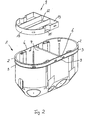
- a hollow wall box 1 is shown, which is molded from plastic and used for electrical installations.
- a hollow wall box 1 can be used in a conventional manner from the front in the breakthrough of a wall of a cavity wall area.
- the hollow wall box has a Einstecktiefenbegrenzungskragen 2, so that the hollow wall box is flush inserted into the corresponding wall breakthrough, in that the recess of the aperture is produced by a rotating element and the edge of the recess is machined by a peripheral counterbore. This makes it possible to bring the collar 2 flush in the wall in which the breakthrough is generated.
- the retaining wall or retaining edges 3 are peripherally provided on the hollow wall box 1, which cooperate with the hole reveal of the corresponding opening of the wall as sealing edges and allow an airtight fit of the box in the wall breakthrough.
- the hollow wall box 1 is only mouth side (in FIG. 1 above) while the walls and bottom of the can are closed.
- cut-out areas may be provided in the bottom of the can to allow cables or the like to be inserted into the can.
- 1 devices 4 are provided on the outer jacket of the can, can be introduced into the mounting screws together with retaining elements in order to clamp the can to the hollow wall can. Such devices are not shown in the drawing. But they are common and known.
- such facilities are in the DE 196 09 709 A1 shown.
- the inside of the can 1 arrangements 5 are provided on which support rings of installation equipment carriers or the like can be fixed by means of screws.
- the hollow wall box 1 is formed overall in plan view as an oval double box.
- the double box is formed by a can body, which is rounded at least in the area in which the collar 2 and the holding surface or retaining edge 3 or sealing edge, semicircular at the longitudinal ends, wherein the two semicircular shapes are connected via straight terminal portions 6.
- the collar 2 is provided projecting radially outward only in the region of the semicircular shapes.
- the holding surfaces or sealing edges 3 are formed by a radially abkragenden surface area or edge region surrounding the semicircular shape and the straight connection areas 6 without interruption.
- the width of the area between the parts 2 and 3 is equal to or greater than the thickness of the wall, in which the opening for receiving the cavity wall box 1 is introduced, so that on the one hand the collar 2 is flush in the surface of the wall and on the other hand, the sealing edge 3 is still in the engagement area of the hole reveal.
- an intermediate wall 7 is inserted into the cavity wall box 1, wherein the straight connection areas 6 are pressed in the assembly target position against the hole reveal the breakthrough of the wall through the inserted partition 7.
- the hollow wall box 1 has inside and opposite each other in the middle between the semicircular forms, ie in the region of the straight connection areas 6, insertion grooves 8, in which the partition wall 7 can be inserted from the can mouth. Depending on the design of the intermediate wall 7, this can completely separate the two installation sites of the double box in the assembly target position used in the double box or even an installation gap for performing electrical lines or the like exhibit.
- a particular embodiment of the hollow wall box 1 provides that a half-lid 9 is provided, which is flush in the mouth of the trained as a double box cavity wall box 1, as for example with reference to FIG. 3 is clarified so that one of the two installation sites is covered.
- the half-lid 9 may have latching projections 10 which engage in recesses 11 in the installation target position.
- the locking recesses 11 are provided in an area between the collar 2 and the sealing edge 3, so that the wind-tightness of the box is not affected by these recesses.
- the half-lid 9 is formed as a trough-like molded part with a bottom 12 and from the bottom abragendem, circumferential collar 13, wherein the half-lid 9 is used with the circumferential collar 13 ahead in the mouth of the double box, as in FIG. 1 is illustrated, so that the bottom 12 in the target mounting position in the Muzzle level of the double box sits and flush with this completes.
- the half-lid 9 can also be used with the ground ahead in the mouth of the cavity wall box 1, as shown in FIG. 2 and 3 is clarified, so that the bottom 12 facing away from the edge of the collar 13 sits in the mouth level of the double box or flush with this.
- the mounting style as in FIG.
- the covered by the half-lid 9 part of the hollow wall box can be easily over-wallpapered or otherwise covered.
- the arrangement according to FIG. 2 and 3 It is possible to fill the space formed by the half-lid 9 between the mouth of the hollow wall box 1 and the bottom 12 of the half-lid by insulating or the like to optionally achieve a sound or thermal insulation, so that the covered by the half-lid 9 installation device as little as possible Noise or heat from the front surface of the hollow wall box 1 can deliver. Subsequently, the balancing mass or the like, which is arranged in the cavity of the half-lid 9, over-decorated or otherwise covered.
- the collar 13 of the half-lid 9 is stiffened by support webs 14.
- the half-lid 9 has in the region of the arrangement of the functional parts 4 and 5 of the cavity wall box 1 edge bulges, so that these components do not interfere with the insertion of the lid.
- this area may be covered by a removable material layer 15, so that depending on the installation method with inserted half-lid 9, the components 4 and 5 of the covered installation space are covered or in the installation way after FIG. 2 and 3 a penetration for the ends of the parts 4 and 5 is created.
Landscapes
- Engineering & Computer Science (AREA)
- Architecture (AREA)
- Civil Engineering (AREA)
- Structural Engineering (AREA)
- Connection Or Junction Boxes (AREA)
- Casings For Electric Apparatus (AREA)
Claims (9)
- Boîte de distribution en plastique montée au mur pour des installations électriques, qui peut être insérée de l'avant dans une orifice d'un mur, la boîte de distribution (1) montée au mur comportant une collerette (2) limitant la profondeur d'insertion pour l'insertion fleurée dans l'orifice et périphériquement des surfaces ou arêtes de retenue (3) pour coopérer avec la surface intérieure de l'orifice dans le mur, et un fond renfermant la boîte de distribution (1) montée au mur, la boîte de distribution (1) montée au mur étant réalisée, vue en plan, comme une boîte double ovale, la boîte double étant formée par un corps de boîte qui au moins dans la zone de la collerette (2) et des surfaces ou arêtes de retenue (3) est arrondi à ses extrémités longitudinales en une forme semi-circulaire, les deux sections semi-circulaires étant liées par des sections de liage (6) rectilignes, et la collerette (2) faisant radialement saillie seulement dans la zone des sections semi-circulaires, caractérisée en ce que les surfaces ou arêtes de retenue (3) sont formées par une section de surface ou d'arête radialement en saillie entourant la section semi-circulaire et les sections de liage (6) rectilignes sans discontinuité sous la forme d'arêtes d'étanchéité.
- Boîte de distribution montée au mur selon la revendication 1, caractérisée en ce que centralement entre les deux sections semi-circulaires au moins près de l'extrémité supérieure de la boîte double, une paroi intermédiaire (7) ou une entretoise intermédiaire peut être insérée, et si l'entretoise intermédiaire ou la paroi intermédiaire (7) est insérée, les sections de liage (6) rectilignes sont poussées contre la surface intérieure de l'orifice.
- Boîte de distribution montée au mur selon la revendication 2, caractérisée en ce que la boîte double a sur son côté intérieur des rainures d'insertion (8) opposées dans la zone centralement entre les sections semi-circulaires, dans lesquelles la paroi intermédiaire (7) ou l'entretoise intermédiaire peut être insérée à partir de l'extrémité supérieure de la boîte.
- Boîte de distribution montée au mur selon la revendication 2 ou 3, caractérisée en ce que la paroi intermédiaire (7) dans la position de montage de consigne, si insérée dans la boîte double, sépare complètement l'une de l'autre les deux positions d'installation de la boîte double.
- Boîte de distribution montée au mur selon la revendication 2 ou 3, caractérisée en ce qu'entre la paroi intermédiaire (7) et le fond de la boîte double, dans la position de montage de consigne de la paroi intermédiaire (7), une fente d'installation pour le passage de câbles électriques ou semblables moyens d'installation est réalisée.
- Boîte de distribution montée au mur selon une des revendications 1 à 5, caractérisée en ce qu'au moins un demi-couvercle (9) est prévu qui peut être inséré à fleur dans l'extrémité supérieure de la boîte double et recouvre une des deux positions d'installation.
- Boîte de distribution montée au mur selon la revendication 6, caractérisée en ce que le demi-couvercle (9) est maintenu par encliquetage dans la boîte double.
- Boîte de distribution montée au mur selon la revendication 6 ou 7, caractérisée en ce que le demi-couvercle (9) est réalisé comme une pièce moulée en forme de cuve avec un fond (12) et une collerette (13) périphérique étant en saillie du fond (12), le couvercle (9) pouvant être inséré alternativement avec la collerette (13) périphérique vers le front dans l'extrémité supérieure de la boîte double, de façon que le fond (12) soit positionné dans le plan de l'extrémité supérieure de la boîte double ou soit à fleur avec celle-ci, ou pouvant être inséré avec le fond (12) vers le front dans l'extrémité supérieure, de façon que l'arête de la collerette (13) à l'opposé du fond (12) soit positionnée dans le plan de l'extrémité supérieure de la boîte double ou soit à fleur avec celle-ci.
- Boîte de distribution montée au mur selon la revendication 8, caractérisée en ce que la collerette (13) du demi-couvercle (9) est renforcée par des entretoises d'appui (14).
Applications Claiming Priority (2)
| Application Number | Priority Date | Filing Date | Title |
|---|---|---|---|
| DE10160736A DE10160736B4 (de) | 2001-12-11 | 2001-12-11 | Hohlwanddose aus Kunststoff |
| DE10160736 | 2001-12-11 |
Publications (2)
| Publication Number | Publication Date |
|---|---|
| EP1320162A1 EP1320162A1 (fr) | 2003-06-18 |
| EP1320162B1 true EP1320162B1 (fr) | 2015-12-30 |
Family
ID=7708751
Family Applications (1)
| Application Number | Title | Priority Date | Filing Date |
|---|---|---|---|
| EP02022007.5A Expired - Lifetime EP1320162B1 (fr) | 2001-12-11 | 2002-10-01 | Boîte de distribution en plastique montée au mur |
Country Status (2)
| Country | Link |
|---|---|
| EP (1) | EP1320162B1 (fr) |
| DE (1) | DE10160736B4 (fr) |
Families Citing this family (4)
| Publication number | Priority date | Publication date | Assignee | Title |
|---|---|---|---|---|
| DE10343489A1 (de) * | 2003-09-19 | 2005-04-14 | Comatec S.N.C. | Transformator, insbesondere Sicherheitstransformator zum Einbau in Unterputzdosen |
| US7375951B2 (en) | 2006-07-07 | 2008-05-20 | Lutron Electronics Co., Inc. | Load control device having a split enclosure |
| BE1020602A3 (de) * | 2012-04-04 | 2014-01-07 | Kaiser Gmbh & Co Kg | Hohlwanddose aus kunststoff. |
| GB2572814B (en) * | 2018-04-12 | 2022-07-13 | Circle Box Ltd | Improved Electrical Back Box |
Family Cites Families (4)
| Publication number | Priority date | Publication date | Assignee | Title |
|---|---|---|---|---|
| DE2526853C2 (de) * | 1975-06-16 | 1982-06-24 | Kaiser GmbH & Co KG, 5885 Schalksmühle | Elektrische Hohlwanddose |
| DE4222042C2 (de) * | 1992-04-29 | 1994-06-16 | Kaiser Gmbh & Co Kg | Elektrische Unterputz-Abzweigdose, insbesondere für den Installationsbus |
| DE19609709C2 (de) * | 1996-03-13 | 1999-05-20 | Kaiser Gmbh & Co Kg | Elektrische Hohlwanddose |
| FR2787644B1 (fr) * | 1998-12-22 | 2001-03-09 | Legrand Sa | Boite d'encastrement, notamment pour cloison seche |
-
2001
- 2001-12-11 DE DE10160736A patent/DE10160736B4/de not_active Expired - Fee Related
-
2002
- 2002-10-01 EP EP02022007.5A patent/EP1320162B1/fr not_active Expired - Lifetime
Also Published As
| Publication number | Publication date |
|---|---|
| EP1320162A1 (fr) | 2003-06-18 |
| DE10160736B4 (de) | 2004-07-29 |
| DE10160736A1 (de) | 2003-06-26 |
Similar Documents
| Publication | Publication Date | Title |
|---|---|---|
| EP3292604B1 (fr) | Procédé de réalisation d'une traversée mural pour plusieurs câbles et ensemble | |
| EP0858690A1 (fr) | Dispositif de connexion d'une enveloppe electriquement conductrice d'un cable avec un fil de masse | |
| EP3091624A1 (fr) | Boitier d'installation pour appareils electriques | |
| EP2650577B1 (fr) | Dispositif permettant de poser des pièces longilignes à travers des parois d'appareil | |
| EP2852017A2 (fr) | Boîtier d'installation à des fins électrotechniques | |
| EP2273633A2 (fr) | Agencement de liaison de deux armoires électriques et armoire électrique destinée à recevoir des appareils d'installation électriques | |
| EP0074427B1 (fr) | Dispositif de fixation d'un appareil électrique, notamment un interrupteur à cames, à une plaque de montage | |
| EP1376795B1 (fr) | Dispositif d'installation de conducteurs d'énergie | |
| EP2738897B1 (fr) | Bouchon étanche | |
| EP1595318B1 (fr) | Passage de cables | |
| DE10160736B4 (de) | Hohlwanddose aus Kunststoff | |
| DE3920964C2 (fr) | ||
| DE102014102260B4 (de) | Baukasten für die Abdichtung des Durchganges von Kabeln oder Adern, die durch eine Platte verlaufen sowie Verfahren zum Abdichten | |
| DE3906366A1 (de) | Lampenfassung fuer kraftfahrzeuge | |
| DE20120003U1 (de) | Hohlwanddose aus Kunststoff | |
| DE3842205C2 (de) | Gehäuse für den Anschluß von Kommunikationssystemen | |
| EP2650994B1 (fr) | Agencement de prises pour canaux d'intégration d'appareils avec rail de maintien sur le fond du canal et canal d'intégration d'appareils comprenant un tel agencement de prises | |
| DE19615951C1 (de) | Mehrphasige Klemmvorrichtung | |
| EP3540884A1 (fr) | Boîte d'installation et entrée de boîte d'installation | |
| EP0435075B1 (fr) | Manchon élastique | |
| DE10141543B4 (de) | Einrichtung zum Festlegen von Gegenständen an einem Widerlager | |
| EP0508175A2 (fr) | Boîte de distribution à but électro-technique à monter sur crépi | |
| DE69800799T2 (de) | Flüssigkeitdichte Kupplung für Gehäuse für elektrische Installation | |
| EP1638180A1 (fr) | Protection de terminaison d'un isolateur | |
| BE1020602A3 (de) | Hohlwanddose aus kunststoff. |
Legal Events
| Date | Code | Title | Description |
|---|---|---|---|
| PUAI | Public reference made under article 153(3) epc to a published international application that has entered the european phase |
Free format text: ORIGINAL CODE: 0009012 |
|
| AK | Designated contracting states |
Designated state(s): AT BE BG CH CY CZ DE DK EE ES FI FR GB GR IE IT LI LU MC NL PT SE SK TR |
|
| AX | Request for extension of the european patent |
Extension state: AL LT LV MK RO SI |
|
| 17P | Request for examination filed |
Effective date: 20030710 |
|
| AKX | Designation fees paid |
Designated state(s): AT BE BG CH CY CZ DE DK EE ES FI FR GB GR IE IT LI LU MC NL PT SE SK TR |
|
| 17Q | First examination report despatched |
Effective date: 20150312 |
|
| GRAP | Despatch of communication of intention to grant a patent |
Free format text: ORIGINAL CODE: EPIDOSNIGR1 |
|
| INTG | Intention to grant announced |
Effective date: 20150729 |
|
| GRAS | Grant fee paid |
Free format text: ORIGINAL CODE: EPIDOSNIGR3 |
|
| GRAA | (expected) grant |
Free format text: ORIGINAL CODE: 0009210 |
|
| AK | Designated contracting states |
Kind code of ref document: B1 Designated state(s): AT BE BG CH CY CZ DE DK EE ES FI FR GB GR IE IT LI LU MC NL PT SE SK TR |
|
| REG | Reference to a national code |
Ref country code: GB Ref legal event code: FG4D Free format text: NOT ENGLISH |
|
| REG | Reference to a national code |
Ref country code: CH Ref legal event code: EP |
|
| REG | Reference to a national code |
Ref country code: AT Ref legal event code: REF Ref document number: 767862 Country of ref document: AT Kind code of ref document: T Effective date: 20160115 |
|
| REG | Reference to a national code |
Ref country code: IE Ref legal event code: FG4D Free format text: LANGUAGE OF EP DOCUMENT: GERMAN |
|
| REG | Reference to a national code |
Ref country code: DE Ref legal event code: R096 Ref document number: 50216111 Country of ref document: DE |
|
| REG | Reference to a national code |
Ref country code: NL Ref legal event code: MP Effective date: 20151230 |
|
| PG25 | Lapsed in a contracting state [announced via postgrant information from national office to epo] |
Ref country code: SE Free format text: LAPSE BECAUSE OF FAILURE TO SUBMIT A TRANSLATION OF THE DESCRIPTION OR TO PAY THE FEE WITHIN THE PRESCRIBED TIME-LIMIT Effective date: 20151230 Ref country code: GR Free format text: LAPSE BECAUSE OF FAILURE TO SUBMIT A TRANSLATION OF THE DESCRIPTION OR TO PAY THE FEE WITHIN THE PRESCRIBED TIME-LIMIT Effective date: 20160331 Ref country code: FI Free format text: LAPSE BECAUSE OF FAILURE TO SUBMIT A TRANSLATION OF THE DESCRIPTION OR TO PAY THE FEE WITHIN THE PRESCRIBED TIME-LIMIT Effective date: 20151230 |
|
| PG25 | Lapsed in a contracting state [announced via postgrant information from national office to epo] |
Ref country code: NL Free format text: LAPSE BECAUSE OF FAILURE TO SUBMIT A TRANSLATION OF THE DESCRIPTION OR TO PAY THE FEE WITHIN THE PRESCRIBED TIME-LIMIT Effective date: 20151230 |
|
| PG25 | Lapsed in a contracting state [announced via postgrant information from national office to epo] |
Ref country code: IT Free format text: LAPSE BECAUSE OF FAILURE TO SUBMIT A TRANSLATION OF THE DESCRIPTION OR TO PAY THE FEE WITHIN THE PRESCRIBED TIME-LIMIT Effective date: 20151230 Ref country code: ES Free format text: LAPSE BECAUSE OF FAILURE TO SUBMIT A TRANSLATION OF THE DESCRIPTION OR TO PAY THE FEE WITHIN THE PRESCRIBED TIME-LIMIT Effective date: 20151230 Ref country code: CZ Free format text: LAPSE BECAUSE OF FAILURE TO SUBMIT A TRANSLATION OF THE DESCRIPTION OR TO PAY THE FEE WITHIN THE PRESCRIBED TIME-LIMIT Effective date: 20151230 |
|
| PG25 | Lapsed in a contracting state [announced via postgrant information from national office to epo] |
Ref country code: SK Free format text: LAPSE BECAUSE OF FAILURE TO SUBMIT A TRANSLATION OF THE DESCRIPTION OR TO PAY THE FEE WITHIN THE PRESCRIBED TIME-LIMIT Effective date: 20151230 Ref country code: PT Free format text: LAPSE BECAUSE OF FAILURE TO SUBMIT A TRANSLATION OF THE DESCRIPTION OR TO PAY THE FEE WITHIN THE PRESCRIBED TIME-LIMIT Effective date: 20160502 Ref country code: EE Free format text: LAPSE BECAUSE OF FAILURE TO SUBMIT A TRANSLATION OF THE DESCRIPTION OR TO PAY THE FEE WITHIN THE PRESCRIBED TIME-LIMIT Effective date: 20151230 |
|
| REG | Reference to a national code |
Ref country code: DE Ref legal event code: R097 Ref document number: 50216111 Country of ref document: DE |
|
| PG25 | Lapsed in a contracting state [announced via postgrant information from national office to epo] |
Ref country code: DK Free format text: LAPSE BECAUSE OF FAILURE TO SUBMIT A TRANSLATION OF THE DESCRIPTION OR TO PAY THE FEE WITHIN THE PRESCRIBED TIME-LIMIT Effective date: 20151230 |
|
| PLBE | No opposition filed within time limit |
Free format text: ORIGINAL CODE: 0009261 |
|
| STAA | Information on the status of an ep patent application or granted ep patent |
Free format text: STATUS: NO OPPOSITION FILED WITHIN TIME LIMIT |
|
| 26N | No opposition filed |
Effective date: 20161003 |
|
| PG25 | Lapsed in a contracting state [announced via postgrant information from national office to epo] |
Ref country code: BE Free format text: LAPSE BECAUSE OF NON-PAYMENT OF DUE FEES Effective date: 20161031 |
|
| REG | Reference to a national code |
Ref country code: CH Ref legal event code: PL |
|
| GBPC | Gb: european patent ceased through non-payment of renewal fee |
Effective date: 20161001 |
|
| REG | Reference to a national code |
Ref country code: IE Ref legal event code: MM4A |
|
| REG | Reference to a national code |
Ref country code: FR Ref legal event code: ST Effective date: 20170630 |
|
| PG25 | Lapsed in a contracting state [announced via postgrant information from national office to epo] |
Ref country code: CH Free format text: LAPSE BECAUSE OF NON-PAYMENT OF DUE FEES Effective date: 20161031 Ref country code: FR Free format text: LAPSE BECAUSE OF NON-PAYMENT OF DUE FEES Effective date: 20161102 Ref country code: LI Free format text: LAPSE BECAUSE OF NON-PAYMENT OF DUE FEES Effective date: 20161031 Ref country code: GB Free format text: LAPSE BECAUSE OF NON-PAYMENT OF DUE FEES Effective date: 20161001 |
|
| PG25 | Lapsed in a contracting state [announced via postgrant information from national office to epo] |
Ref country code: LU Free format text: LAPSE BECAUSE OF NON-PAYMENT OF DUE FEES Effective date: 20161001 |
|
| PG25 | Lapsed in a contracting state [announced via postgrant information from national office to epo] |
Ref country code: IE Free format text: LAPSE BECAUSE OF NON-PAYMENT OF DUE FEES Effective date: 20161001 |
|
| REG | Reference to a national code |
Ref country code: BE Ref legal event code: MM Effective date: 20161031 |
|
| REG | Reference to a national code |
Ref country code: AT Ref legal event code: MM01 Ref document number: 767862 Country of ref document: AT Kind code of ref document: T Effective date: 20161001 |
|
| PG25 | Lapsed in a contracting state [announced via postgrant information from national office to epo] |
Ref country code: AT Free format text: LAPSE BECAUSE OF NON-PAYMENT OF DUE FEES Effective date: 20161001 |
|
| PG25 | Lapsed in a contracting state [announced via postgrant information from national office to epo] |
Ref country code: CY Free format text: LAPSE BECAUSE OF FAILURE TO SUBMIT A TRANSLATION OF THE DESCRIPTION OR TO PAY THE FEE WITHIN THE PRESCRIBED TIME-LIMIT Effective date: 20151230 |
|
| PG25 | Lapsed in a contracting state [announced via postgrant information from national office to epo] |
Ref country code: MC Free format text: LAPSE BECAUSE OF FAILURE TO SUBMIT A TRANSLATION OF THE DESCRIPTION OR TO PAY THE FEE WITHIN THE PRESCRIBED TIME-LIMIT Effective date: 20151230 Ref country code: TR Free format text: LAPSE BECAUSE OF FAILURE TO SUBMIT A TRANSLATION OF THE DESCRIPTION OR TO PAY THE FEE WITHIN THE PRESCRIBED TIME-LIMIT Effective date: 20151230 |
|
| PG25 | Lapsed in a contracting state [announced via postgrant information from national office to epo] |
Ref country code: BG Free format text: LAPSE BECAUSE OF FAILURE TO SUBMIT A TRANSLATION OF THE DESCRIPTION OR TO PAY THE FEE WITHIN THE PRESCRIBED TIME-LIMIT Effective date: 20151230 |
|
| PGFP | Annual fee paid to national office [announced via postgrant information from national office to epo] |
Ref country code: DE Payment date: 20211229 Year of fee payment: 20 |
|
| REG | Reference to a national code |
Ref country code: DE Ref legal event code: R071 Ref document number: 50216111 Country of ref document: DE |