EP1320176A2 - Dispositif d'actionnement, notamment pour actionner le verouillage d'un différentiel dans des véhicules - Google Patents
Dispositif d'actionnement, notamment pour actionner le verouillage d'un différentiel dans des véhicules Download PDFInfo
- Publication number
- EP1320176A2 EP1320176A2 EP02027038A EP02027038A EP1320176A2 EP 1320176 A2 EP1320176 A2 EP 1320176A2 EP 02027038 A EP02027038 A EP 02027038A EP 02027038 A EP02027038 A EP 02027038A EP 1320176 A2 EP1320176 A2 EP 1320176A2
- Authority
- EP
- European Patent Office
- Prior art keywords
- actuating device
- sensor
- commutator
- wheel
- actuating
- Prior art date
- Legal status (The legal status is an assumption and is not a legal conclusion. Google has not performed a legal analysis and makes no representation as to the accuracy of the status listed.)
- Granted
Links
- 239000000463 material Substances 0.000 claims description 6
- 230000005405 multipole Effects 0.000 claims description 3
- 239000000696 magnetic material Substances 0.000 claims description 2
- 150000001875 compounds Chemical class 0.000 description 4
- 238000000465 moulding Methods 0.000 description 3
- 238000004804 winding Methods 0.000 description 3
- RYGMFSIKBFXOCR-UHFFFAOYSA-N Copper Chemical compound [Cu] RYGMFSIKBFXOCR-UHFFFAOYSA-N 0.000 description 2
- 239000004020 conductor Substances 0.000 description 2
- 229910052802 copper Inorganic materials 0.000 description 2
- 239000010949 copper Substances 0.000 description 2
- 238000004519 manufacturing process Methods 0.000 description 2
- 230000000694 effects Effects 0.000 description 1
- 238000005516 engineering process Methods 0.000 description 1
- 238000009434 installation Methods 0.000 description 1
- 239000011810 insulating material Substances 0.000 description 1
- 230000003993 interaction Effects 0.000 description 1
- 238000000034 method Methods 0.000 description 1
- 238000003801 milling Methods 0.000 description 1
- 238000003466 welding Methods 0.000 description 1
Images



Classifications
-
- H—ELECTRICITY
- H02—GENERATION; CONVERSION OR DISTRIBUTION OF ELECTRIC POWER
- H02K—DYNAMO-ELECTRIC MACHINES
- H02K7/00—Arrangements for handling mechanical energy structurally associated with dynamo-electric machines, e.g. structural association with mechanical driving motors or auxiliary dynamo-electric machines
- H02K7/10—Structural association with clutches, brakes, gears, pulleys or mechanical starters
- H02K7/102—Structural association with clutches, brakes, gears, pulleys or mechanical starters with friction brakes
- H02K7/1021—Magnetically influenced friction brakes
- H02K7/1023—Magnetically influenced friction brakes using electromagnets
- H02K7/1025—Magnetically influenced friction brakes using electromagnets using axial electromagnets with generally annular air gap
-
- H—ELECTRICITY
- H02—GENERATION; CONVERSION OR DISTRIBUTION OF ELECTRIC POWER
- H02K—DYNAMO-ELECTRIC MACHINES
- H02K11/00—Structural association of dynamo-electric machines with electric components or with devices for shielding, monitoring or protection
- H02K11/20—Structural association of dynamo-electric machines with electric components or with devices for shielding, monitoring or protection for measuring, monitoring, testing, protecting or switching
- H02K11/21—Devices for sensing speed or position, or actuated thereby
- H02K11/215—Magnetic effect devices, e.g. Hall-effect or magneto-resistive elements
-
- H—ELECTRICITY
- H02—GENERATION; CONVERSION OR DISTRIBUTION OF ELECTRIC POWER
- H02K—DYNAMO-ELECTRIC MACHINES
- H02K5/00—Casings; Enclosures; Supports
- H02K5/04—Casings or enclosures characterised by the shape, form or construction thereof
- H02K5/14—Means for supporting or protecting brushes or brush holders
- H02K5/143—Means for supporting or protecting brushes or brush holders for cooperation with commutators
- H02K5/148—Slidably supported brushes
Definitions
- the invention relates to an actuating device, in particular for the actuation of limited slip differentials Vehicles.
- Such actuators are particularly in the Motor vehicle to support the drive and Brake systems use. They regularly include one Drive unit for driving an actuating shaft and a braking unit for braking the actuating shaft. about the actuating shaft can lock or lock a differential be switched off. The actual switching process takes over the drive unit.
- the brake unit stops the actuating shaft in a predetermined position.
- Such actuators are high To make demands.
- the Actuating shaft may also only be a relatively small one Subject to safe operation of the game To be able to guarantee limited slip differentials.
- the actuator has a simple structure and be easy to assemble.
- the Actuator should also be compact.
- the present invention is therefore based on the object to propose an actuator in which especially a very precise actuation of the actuation shaft is possible.
- the actuator should be as possible have few components.
- a sensor unit for measuring the angle of rotation has the advantage that the exact position of the Actuating shaft can be determined. For the exact switching of the for example limited slip differential, it is necessary Specify or close the angle of rotation of the actuating shaft exactly determine.
- the encoder wheel is preferably in one piece with the Brake hub flange designed.
- the encompassing the encoder wheel Brake hub flange can therefore be used as a separate component be handled. They also reduce due to the one-part training the component tolerances.
- Another embodiment of the invention provides that Encoder wheel on the free end of the actuating shaft side facing away or on the side facing the commutator Side of the brake hub flange is arranged. This has the Advantage that the encoder wheel is arranged in one area that is not required for other components.
- the encoder wheel is not on that Brake hub flange, but to be arranged on the commutator.
- This arrangement also has the advantage that none additional mounting of the encoder wheel on the actuating shaft is required.
- the number of tolerances; the predetermined dimension of the air gap between The encoder wheel and sensor can be used with less manufacturing technology Effort must be met.
- the transmitter wheel is advantageously on the anchor package arranged opposite end of the commutator.
- the area of the commutator is an arrangement of the encoder wheel possible without affecting other components.
- a particularly preferred embodiment of the invention is characterized in that the encoder wheel in the Commutator is integrated. This has the advantage that for the encoder wheel does not provide any additional installation space is. The entire actuator can therefore be smaller to build.
- the commutator has an external one Contact layer and an inner, forming the encoder wheel, Core.
- the contact layer is advantageously made of an electrically conductive material, such as Copper. It serves as a contact system for brushes that work with the Interact commutator.
- This intermediate layer can be electrically insulating and consist in particular of molding compound.
- Advantage of one such intermediate layer is that possible Interactions between the contact layer and the that The core of the commutator that forms the encoder wheel can be prevented.
- An advantageous embodiment of the commutator draws is characterized in that the commutator is directed radially inwards has directed slits that the contact layer in Divide the slats or into ring segments.
- the slots are advantageously so deep that they divide the encoder wheel into encoder wheel segments, with the Reasons of the slits in the core forming the encoder wheel lie.
- the lamellae or the ring segments advantageously form the commutator's encoder wheel.
- the slats or the Ring segments then have a corresponding material his.
- Such an embodiment of the invention has the Advantage that there is no need for an additional encoder wheel Components and processing steps can be saved.
- the direct scanning of the slats or ring segments of the The commutator advantageously takes place in the area of Welding hooks.
- Another preferred embodiment of the invention is characterized in that on the free end of the Actuating shaft facing side of the commutator or between the brake hub flange and the commutator Brush holder plate with quivers and brushes for contacting the commutator is arranged.
- the Brush plate in addition to the quivers and brushes also the sensor on.
- the encoder wheel can either be connected to the commutator or integrated in this, or on the brake hub flange be provided.
- the sensor can either the radial or the encoder wheel scan others axially.
- the sensor unit can in particular be used as a Hall sensor unit be trained.
- the sensor can be magnetic preloaded and the encoder wheel made of ferritic material.
- the sensor cannot be magnetically biased and the encoder wheel made of magnetic material or as a multipole ring be trained.
- the housing advantageously has a cup-shaped one Basic housing and a housing cover with an opening for the actuating shaft.
- the drive unit can in the basic housing and the brake unit in the Housing cover to be housed.
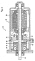
- the Actuator 10 has one at the free end Actuating shaft 12 has a pinion 14, via which a Not shown differential lock of a vehicle can be operated.
- the Actuator a drive unit 16 and electromagnetic brake unit 18, the Drive unit 16 and the brake unit 18 in one common housing 20 is housed.
- the housing 20 comprises a cup-shaped base housing 22, which the Drive unit 16 receives.
- the housing 20 further comprises a housing cover 24 in which the brake unit 18th is housed. By means of connecting screws 26 Housing cover 24 tightly screwed to the base housing 20 become.
- the drive unit 16 comprises permanent magnets on the housing side 28, the one on the actuating shaft 12 rotatably arranged anchor package 30 cooperate. Also includes the drive unit 16 one on the operating shaft non-rotatably arranged commutator 32 against which The outer surface of brushes 36 mounted in quivers 34 act.
- the Quiver 34 are in this case perpendicular to the longitudinal axis 38 the actuating shaft 12 arranged brush support plate 40 attached.
- the brake unit 18 includes a non-rotatable on the Actuating shaft 12 arranged brake hub flange 42 and one against the housing cover 24 secured against rotation, one Brake winding 44 comprising brake body 46. Also includes the brake unit 18 opposite the actuating shaft 12 rotatably arranged, axially movable brake disc 48, which is designed as a brake disc ring. at Energizing the brake winding 44 acts on the brake disc 48 against the likewise annular brake body 46. Consequently, when the brake winding 46 is energized, the Braking effect and the actuating shaft 12 is on the Brake hub flange 42, the brake disc 48 and the Brake body 46 against the housing 20 or against the Housing cover 24 secured against rotation.
- the brake body 46 in the housing cover 24 sees the Brake body 46 extending coaxially to the longitudinal axis 38 Pin 50 in front, which in appropriately trained, projecting blind holes 52 on the housing cover side.
- the brake body 46 within the housing cover 24 are caulking sections 54 on the housing cover 24 provided that in corresponding sections on the Shell surface of the brake body 46 are caulked.
- a spring element 58 provided that the brake disc 48 against the Brake disc support section 56 acted upon.
- a transmitter wheel 66 To detect the angle of rotation of the Actuating shaft 12 is on the brush support plate 40 facing side of the brake hub flange 42 or the Brush carrier section 56 arranged a transmitter wheel 66.
- the encoder wheel 66 is on by means of two bores 68 Mounting pin 70 of the brake hub flange 42 attached.
- the encoder wheel is preferably made of a ferritic one Material or designed as a multipole ring.
- the arrangement of the encoder wheel 66 on the brake hub flange 42 has the advantage that none for holding the encoder wheel 66 additional components are to be provided.
- the actuator 80 differs from that Actuator 10 and others in that for determination of the angle of rotation of the actuating shaft 12, the encoder wheel 66 is not scanned radially, but in the axial direction. For this there is at least one correspondingly arranged Hall sensor 82 provided.
- the actuating device 90 shown in FIG. 4 has a transmitter wheel 92, which on the brush support plate 40 or the brake unit 18 facing the end of the Commutator 32 is arranged.
- the encoder wheel 92 is preferably in sections in the commutator material, embedded in and in particular in molding compound Brush support plate 40.
- the encoder wheel 92 and the commutator 32 form a jointly manageable component.
- Actuator 90 has a sensor 94 in shape of a Hall sensor.
- Hall sensor 94 is such arranged to radially scan the encoder wheel 92.
- the Hall sensor 94 is on the brush support plate 40 arranged.
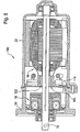
- the actuating device 100 shown in FIG. 5 has a sensor wheel 102, which is completely in the commutators 103 is integrated.
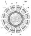
- Figure 6 is a cross section through the Commutator 103 shown.
- the contact layer 104 is made of a conductive Material, especially copper.
- the encoder wheel 102 is an inner core of the Commutator 103 formed.
- Between the core and the Contact layer 104 is an intermediate layer 106 especially insulating material such as Press compound provided.
- an inner layer 108 is present which also preferably consists of molding compound.
- the commutator 103 detects radially inward slots 110 on the Contact layer 104 in lamellae or in ring segments divide.
- the slots 110 also divide that Encoder wheel 102 in tooth-like encoder wheel segments 112, the Reasons 114 of the slots 110 in which the encoder wheel 102 forming the core of the commutator 103.
- the individual commutator layers can be used as interlocking cylinder rings are produced.
- the Slits 110 can be cut, for example or milling.
- the respective position or the respective angle of rotation of the Encoder wheel 102 and the commutator 103 is by on the Brush support plate 40 existing sensors 116, in particular Hall sensors, scanned. The scanning takes place according to the figure 5 in the radial direction.
- the contact layer 104 or Scanning slats or ring segments directly. These should be then be made of a suitable material. At a such embodiment will then not be an extra encoder wheel to be manufactured required.
Landscapes
- Engineering & Computer Science (AREA)
- Power Engineering (AREA)
- Physics & Mathematics (AREA)
- Electromagnetism (AREA)
- Microelectronics & Electronic Packaging (AREA)
- Braking Arrangements (AREA)
- Transmission And Conversion Of Sensor Element Output (AREA)
- Retarders (AREA)
Applications Claiming Priority (2)
| Application Number | Priority Date | Filing Date | Title |
|---|---|---|---|
| DE10160846A DE10160846A1 (de) | 2001-12-12 | 2001-12-12 | Betätigungsvorrichtung, insbesondere zur Betätigung von Sperrdifferentialen von Fahrzeugen |
| DE10160846 | 2001-12-12 |
Publications (3)
| Publication Number | Publication Date |
|---|---|
| EP1320176A2 true EP1320176A2 (fr) | 2003-06-18 |
| EP1320176A3 EP1320176A3 (fr) | 2005-02-16 |
| EP1320176B1 EP1320176B1 (fr) | 2010-05-12 |
Family
ID=7708814
Family Applications (1)
| Application Number | Title | Priority Date | Filing Date |
|---|---|---|---|
| EP02027038A Expired - Lifetime EP1320176B1 (fr) | 2001-12-12 | 2002-12-03 | Dispositif d'actionnement, notamment pour actionner le verouillage d'un différentiel dans des véhicules |
Country Status (4)
| Country | Link |
|---|---|
| US (1) | US6879072B2 (fr) |
| EP (1) | EP1320176B1 (fr) |
| DE (2) | DE10160846A1 (fr) |
| ES (1) | ES2345763T3 (fr) |
Cited By (4)
| Publication number | Priority date | Publication date | Assignee | Title |
|---|---|---|---|---|
| WO2007121828A3 (fr) * | 2006-04-19 | 2007-12-06 | Buhler Motor Gmbh | Bloc pour un moteur à collecteur, moteur à collecteur comprenant ce bloc et procédé de montage d'un tel moteur à collecteur |
| DE102007026937A1 (de) * | 2007-06-12 | 2008-12-24 | Bühler Motor GmbH | Stellantrieb für Kfz-Verteilergetriebe |
| WO2011107407A3 (fr) * | 2010-03-01 | 2012-03-08 | Nuova Sme S.P.A. | Structure de moteur électrique, en particulier pour des moteurs à engrenages pour des manivelles de lève-glace, des sièges, des essuie-glaces, et d'autres applications dans des véhicules |
| WO2021244715A1 (fr) | 2020-06-02 | 2021-12-09 | Linak A/S | Verrouillage contre la rotation d'un moteur électrique d'un actionneur linéaire |
Families Citing this family (7)
| Publication number | Priority date | Publication date | Assignee | Title |
|---|---|---|---|---|
| NZ540311A (en) * | 2004-06-19 | 2006-11-30 | Inventio Ag | Drive for a lift installation |
| DE102005021901A1 (de) * | 2005-05-12 | 2006-11-16 | Zf Friedrichshafen Ag | Vorrichtung und Verfahren zum Einstellen einer Übertragungsfähigkeit eines reibschlüssigen Schaltelementes |
| US7852183B2 (en) * | 2005-11-14 | 2010-12-14 | Honeywell International Inc. | Power drive unit electromagnetic latch |
| US7602271B2 (en) * | 2006-08-21 | 2009-10-13 | American Axle & Manufacturing, Inc. | Electronically actuated apparatus using solenoid actuator with integrated sensor |
| US7777385B2 (en) * | 2008-05-15 | 2010-08-17 | Honeywell International Inc. | Compact, electromagnetically braked actuator assembly |
| US11025133B2 (en) * | 2019-02-20 | 2021-06-01 | Dana Automotive Systems Group, Llc | Electric motor brake |
| EP4502412B1 (fr) * | 2023-08-03 | 2026-03-18 | Warner Electric Technology LLC | Frein avec capteur de position de moteur intégré |
Citations (2)
| Publication number | Priority date | Publication date | Assignee | Title |
|---|---|---|---|---|
| US2514693A (en) | 1944-06-21 | 1950-07-11 | Garrett Corp | Motor assembly with magnetic brake |
| WO1999043071A1 (fr) | 1998-02-21 | 1999-08-26 | Valeo Auto-Electric Wischer Und Motoren Gmbh | Dispositif de mesure d'angle de rotation a collecteur magnetise |
Family Cites Families (10)
| Publication number | Priority date | Publication date | Assignee | Title |
|---|---|---|---|---|
| US2520204A (en) * | 1945-07-02 | 1950-08-29 | Nader Engineering Company | Electromagnetically controlled brake |
| US3277357A (en) * | 1963-06-04 | 1966-10-04 | Ampex | Speed control for a rotary device by means of braking |
| FR2126563A5 (fr) * | 1971-02-10 | 1972-10-06 | Samm | |
| DE3602292A1 (de) * | 1986-01-25 | 1987-08-06 | Audi Ag | Geberanordnung |
| JPS63190532A (ja) | 1987-01-29 | 1988-08-08 | Fuji Electric Co Ltd | パルスエンコ−ダ付きブレ−キモ−タ |
| JPH02246766A (ja) * | 1989-03-16 | 1990-10-02 | Mitsubishi Electric Corp | 電磁ブレーキ装置 |
| DE19526820C2 (de) * | 1995-07-12 | 1998-01-22 | Brose Fahrzeugteile | Vorrichtung zur Erfassung der Drehzahl, Drehrichtung und/oder Drehwinkelstellung eines Kommutatormotors |
| US5982063A (en) * | 1997-12-18 | 1999-11-09 | Unique Mobility, Inc. | Electric motor with internal brake |
| DE19945657C1 (de) * | 1999-09-23 | 2001-03-15 | Siemens Ag | Kommutatormotor mit einer Drehzahl- und/oder Drehrichtungs-Sensorvorrichtung |
| US6550599B2 (en) * | 2000-06-06 | 2003-04-22 | Asmo Co., Ltd. | Motor having clutch and manufacturing method thereof |
-
2001
- 2001-12-12 DE DE10160846A patent/DE10160846A1/de not_active Ceased
-
2002
- 2002-12-03 ES ES02027038T patent/ES2345763T3/es not_active Expired - Lifetime
- 2002-12-03 DE DE50214425T patent/DE50214425D1/de not_active Expired - Lifetime
- 2002-12-03 EP EP02027038A patent/EP1320176B1/fr not_active Expired - Lifetime
- 2002-12-12 US US10/318,990 patent/US6879072B2/en not_active Expired - Fee Related
Patent Citations (2)
| Publication number | Priority date | Publication date | Assignee | Title |
|---|---|---|---|---|
| US2514693A (en) | 1944-06-21 | 1950-07-11 | Garrett Corp | Motor assembly with magnetic brake |
| WO1999043071A1 (fr) | 1998-02-21 | 1999-08-26 | Valeo Auto-Electric Wischer Und Motoren Gmbh | Dispositif de mesure d'angle de rotation a collecteur magnetise |
Cited By (5)
| Publication number | Priority date | Publication date | Assignee | Title |
|---|---|---|---|---|
| WO2007121828A3 (fr) * | 2006-04-19 | 2007-12-06 | Buhler Motor Gmbh | Bloc pour un moteur à collecteur, moteur à collecteur comprenant ce bloc et procédé de montage d'un tel moteur à collecteur |
| DE102007026937A1 (de) * | 2007-06-12 | 2008-12-24 | Bühler Motor GmbH | Stellantrieb für Kfz-Verteilergetriebe |
| DE102007026937B4 (de) * | 2007-06-12 | 2025-10-23 | Bühler Motor GmbH | Stellantrieb für ein Kfz-Verteilergetriebe |
| WO2011107407A3 (fr) * | 2010-03-01 | 2012-03-08 | Nuova Sme S.P.A. | Structure de moteur électrique, en particulier pour des moteurs à engrenages pour des manivelles de lève-glace, des sièges, des essuie-glaces, et d'autres applications dans des véhicules |
| WO2021244715A1 (fr) | 2020-06-02 | 2021-12-09 | Linak A/S | Verrouillage contre la rotation d'un moteur électrique d'un actionneur linéaire |
Also Published As
| Publication number | Publication date |
|---|---|
| DE50214425D1 (de) | 2010-06-24 |
| US20030218392A1 (en) | 2003-11-27 |
| US6879072B2 (en) | 2005-04-12 |
| DE10160846A1 (de) | 2003-07-10 |
| ES2345763T3 (es) | 2010-10-01 |
| EP1320176A3 (fr) | 2005-02-16 |
| EP1320176B1 (fr) | 2010-05-12 |
Similar Documents
| Publication | Publication Date | Title |
|---|---|---|
| EP1301977B1 (fr) | Moteur electrique avec ensemble rotor et procede de realisation | |
| DE69737869T2 (de) | Getriebemotor, insbesondere zum Antrieb von Zubehörteilen in Kraftfahrzeugen | |
| EP3737817A1 (fr) | Système d'entraînement motorisé, utilisation du système d'entraînement pour l'actionnement d'une porte, procédé de fabrication pour un système d'entraînement | |
| EP2297839A2 (fr) | Unité d'entraînement à engrenage comprenant un dispositif autobloquant | |
| EP1320176B1 (fr) | Dispositif d'actionnement, notamment pour actionner le verouillage d'un différentiel dans des véhicules | |
| WO2015044034A2 (fr) | Machine électrique et unité de raccordement pour machine électrique | |
| DE102020130944A1 (de) | Isoliervorrichtung für ein Lager | |
| DE10051403A1 (de) | Rotorbaugruppe für einen Elektromotor und Innenläufer-Elektromotor | |
| EP1528656B1 (fr) | Porte-balais pour un mécanisme de commande à moteur électrique et mécanisme de commande à moteur électrique | |
| DE10312614A1 (de) | Elektrische Maschine mit in den Stator integrierter Rotorlagerung | |
| EP3894726B1 (fr) | Rotor avec filetage d'une seule pièce et moteur électrique, actionneur et frein de stationnement | |
| EP1320175A2 (fr) | Dispositif d'actionnement, notamment pour actionner le verouillage d'un différentiel dans des véhicules | |
| DE19902371A1 (de) | Scheibenläufermotor | |
| DE102015017076A1 (de) | Elektrische Maschine, insbesondere Elektromotor für ein Kraftfahrzeug | |
| WO2007121828A2 (fr) | Bloc pour un moteur à collecteur, moteur à collecteur comprenant ce bloc et procédé de montage d'un tel moteur à collecteur | |
| EP1820251B1 (fr) | Dispositif de verrouillage, unite d'entrainement a engrenage comprenant un dispositif de verrouillage de ce type, et procede pour realiser une unite d'entrainement a engrenage de ce type | |
| DE102023104150A1 (de) | Motorvorrichtung | |
| DE102008025512A1 (de) | Verfahren zum Zusammenbau des Stators einer elektrischen Maschine sowie elektrische Maschine | |
| DE102022103482A1 (de) | Drehantriebsvorrichtung | |
| EP1704631A1 (fr) | Dispositif d'entrainement a moteur electrique | |
| DE102009028036A1 (de) | Elektromotor mit Permanentmagnet-Erregung | |
| DE10359577A1 (de) | Rotor oder Statormodul für einen elektromotorischen Antrieb | |
| EP1334872B1 (fr) | Dispositif de réglage, notamment pour un rétroviseur d'un véhicule | |
| EP1958315B1 (fr) | Dispositif de blocage, unité d entraînement à engrenage comprenant un tel dispositif de blocage et procédé pour fabriquer une telle unité d entraînement à engrenage | |
| DE68914085T2 (de) | Betätigungsgerät, insbesondere zum Ver- und Entriegeln einer Motorfahrzeugstür. |
Legal Events
| Date | Code | Title | Description |
|---|---|---|---|
| PUAI | Public reference made under article 153(3) epc to a published international application that has entered the european phase |
Free format text: ORIGINAL CODE: 0009012 |
|
| 17P | Request for examination filed |
Effective date: 20021203 |
|
| AK | Designated contracting states |
Designated state(s): AT BE BG CH CY CZ DE DK EE ES FI FR GB GR IE IT LI LU MC NL PT SE SI SK TR |
|
| AX | Request for extension of the european patent |
Extension state: AL LT LV MK RO |
|
| PUAL | Search report despatched |
Free format text: ORIGINAL CODE: 0009013 |
|
| AK | Designated contracting states |
Kind code of ref document: A3 Designated state(s): AT BE BG CH CY CZ DE DK EE ES FI FR GB GR IE IT LI LU MC NL PT SE SI SK TR |
|
| AX | Request for extension of the european patent |
Extension state: AL LT LV MK RO |
|
| AKX | Designation fees paid |
Designated state(s): DE ES FR GB IT |
|
| GRAP | Despatch of communication of intention to grant a patent |
Free format text: ORIGINAL CODE: EPIDOSNIGR1 |
|
| GRAS | Grant fee paid |
Free format text: ORIGINAL CODE: EPIDOSNIGR3 |
|
| GRAA | (expected) grant |
Free format text: ORIGINAL CODE: 0009210 |
|
| AK | Designated contracting states |
Kind code of ref document: B1 Designated state(s): DE ES FR GB IT |
|
| REG | Reference to a national code |
Ref country code: GB Ref legal event code: FG4D Free format text: NOT ENGLISH |
|
| REF | Corresponds to: |
Ref document number: 50214425 Country of ref document: DE Date of ref document: 20100624 Kind code of ref document: P |
|
| RAP2 | Party data changed (patent owner data changed or rights of a patent transferred) |
Owner name: NIDEC MOTORS & ACTUATORS GMBH (GERMANY) |
|
| REG | Reference to a national code |
Ref country code: ES Ref legal event code: FG2A Ref document number: 2345763 Country of ref document: ES Kind code of ref document: T3 |
|
| PLBE | No opposition filed within time limit |
Free format text: ORIGINAL CODE: 0009261 |
|
| STAA | Information on the status of an ep patent application or granted ep patent |
Free format text: STATUS: NO OPPOSITION FILED WITHIN TIME LIMIT |
|
| 26N | No opposition filed |
Effective date: 20110215 |
|
| REG | Reference to a national code |
Ref country code: DE Ref legal event code: R097 Ref document number: 50214425 Country of ref document: DE Effective date: 20110214 |
|
| REG | Reference to a national code |
Ref country code: DE Ref legal event code: R081 Ref document number: 50214425 Country of ref document: DE Owner name: NIDEC MOTORS AND ACTUATORS (GERMANY) GMBH, DE Free format text: FORMER OWNER: VALEO MOTOREN UND AKTUATOREN GMBH, 74321 BIETIGHEIM-BISSINGEN, DE |
|
| REG | Reference to a national code |
Ref country code: FR Ref legal event code: CD Owner name: NIDEC MOTORS AND ACTUATORS GERMANY GMBH, DE Effective date: 20151013 |
|
| REG | Reference to a national code |
Ref country code: FR Ref legal event code: PLFP Year of fee payment: 14 |
|
| REG | Reference to a national code |
Ref country code: FR Ref legal event code: PLFP Year of fee payment: 15 |
|
| REG | Reference to a national code |
Ref country code: FR Ref legal event code: PLFP Year of fee payment: 16 |
|
| PGFP | Annual fee paid to national office [announced via postgrant information from national office to epo] |
Ref country code: DE Payment date: 20191210 Year of fee payment: 18 |
|
| PGFP | Annual fee paid to national office [announced via postgrant information from national office to epo] |
Ref country code: IT Payment date: 20191216 Year of fee payment: 18 Ref country code: FR Payment date: 20191218 Year of fee payment: 18 |
|
| PGFP | Annual fee paid to national office [announced via postgrant information from national office to epo] |
Ref country code: ES Payment date: 20200121 Year of fee payment: 18 Ref country code: GB Payment date: 20191220 Year of fee payment: 18 |
|
| REG | Reference to a national code |
Ref country code: DE Ref legal event code: R119 Ref document number: 50214425 Country of ref document: DE |
|
| GBPC | Gb: european patent ceased through non-payment of renewal fee |
Effective date: 20201203 |
|
| PG25 | Lapsed in a contracting state [announced via postgrant information from national office to epo] |
Ref country code: FR Free format text: LAPSE BECAUSE OF NON-PAYMENT OF DUE FEES Effective date: 20201231 Ref country code: IT Free format text: LAPSE BECAUSE OF NON-PAYMENT OF DUE FEES Effective date: 20201203 |
|
| PG25 | Lapsed in a contracting state [announced via postgrant information from national office to epo] |
Ref country code: GB Free format text: LAPSE BECAUSE OF NON-PAYMENT OF DUE FEES Effective date: 20201203 Ref country code: DE Free format text: LAPSE BECAUSE OF NON-PAYMENT OF DUE FEES Effective date: 20210701 |
|
| REG | Reference to a national code |
Ref country code: ES Ref legal event code: FD2A Effective date: 20220207 |
|
| PG25 | Lapsed in a contracting state [announced via postgrant information from national office to epo] |
Ref country code: ES Free format text: LAPSE BECAUSE OF NON-PAYMENT OF DUE FEES Effective date: 20201204 |