EP1321556A2 - Verfahren und Vorrichtung zum Regeln des Stofftransportes bei einer Näh- oder Stickmaschine - Google Patents
Verfahren und Vorrichtung zum Regeln des Stofftransportes bei einer Näh- oder Stickmaschine Download PDFInfo
- Publication number
- EP1321556A2 EP1321556A2 EP02405896A EP02405896A EP1321556A2 EP 1321556 A2 EP1321556 A2 EP 1321556A2 EP 02405896 A EP02405896 A EP 02405896A EP 02405896 A EP02405896 A EP 02405896A EP 1321556 A2 EP1321556 A2 EP 1321556A2
- Authority
- EP
- European Patent Office
- Prior art keywords
- sewing
- actual
- sensor
- step size
- feed
- Prior art date
- Legal status (The legal status is an assumption and is not a legal conclusion. Google has not performed a legal analysis and makes no representation as to the accuracy of the status listed.)
- Granted
Links
Images



Classifications
-
- D—TEXTILES; PAPER
- D05—SEWING; EMBROIDERING; TUFTING
- D05B—SEWING
- D05B27/00—Work-feeding means
- D05B27/10—Work-feeding means with rotary circular feed members
- D05B27/14—Work-feeding means with rotary circular feed members rotating discontinuously
-
- D—TEXTILES; PAPER
- D05—SEWING; EMBROIDERING; TUFTING
- D05B—SEWING
- D05B19/00—Program-controlled sewing machines
- D05B19/02—Sewing machines having electronic memory or microprocessor control unit
- D05B19/12—Sewing machines having electronic memory or microprocessor control unit characterised by control of operation of machine
- D05B19/16—Control of workpiece movement, e.g. modulation of travel of feed dog
-
- D—TEXTILES; PAPER
- D05—SEWING; EMBROIDERING; TUFTING
- D05B—SEWING
- D05B27/00—Work-feeding means
- D05B27/22—Work-feeding means with means for setting length of stitch
Definitions
- the invention relates to a method for controlling the Fabric transport with a sewing or embroidery machine according to the features of claim 1, and a Device for performing the method according to Claim 6.
- Sewing material or fabric After the execution of a Sewing stitch through a fabric feed device.
- Mass transport devices are below, for example a slider arranged on a stitch plate or drivable embroidery hoop.
- Knobs can have one or more horizontal bars, which are sawtooth-shaped on their side facing the material.
- the fabric pusher After each sewing stitch has been carried out, ie after the sewing needle is no longer in contact with the sewing material, the fabric pusher carries out one or more cyclical movements, whereby the sewing material is transported in the sewing direction by one or more increments.
- the fabric pusher is raised so far that the bars reach through slot-shaped openings in the needle plate and come into contact with the sewing material.
- the sewing material is pressed by a presser foot against the needle plate or against the bars reaching through the needle plate.
- the fabric pusher then carries out a pushing movement in the sewing direction, whereby the sewing material is transported by one step in the sewing direction.
- the fabric pusher lowers again so that the bars no longer protrude beyond the stitch plate and returns to its original position.
- the individual partial movements can be combined to form a continuous sequence of movements.
- the sewing direction can be reversed by reversing the movement sequence described, so that the new sewing direction runs counter to the original sewing direction.
- Sewing machine models are also known in which the fabric pusher can carry out transport movements vertically to the sewing direction in an analogous manner in addition to the sewing direction, so that the fabric or the sewing material can be displaced in two dimensions or in a sewing plane predetermined by the surface of the stitch plate.
- Such sewing machines can be used to embroider small patterns.
- an embroidery hoop can be used to embroider patterns.
- an embroidery frame which can be driven by two stepper motors, for example, is used to move the sewing material in the vicinity plane, the fabric or the sewing material being clamped in this embroidery frame. After a sewing stitch has been carried out, the embroidery hoop is moved by means of the two stepper motors in such a way that the new puncture point comes to rest under the sewing needle.
- the embroidery hoop is moved by means of the two stepper motors in such a way that the new puncture point comes to rest under the sewing needle.
- specified stitch widths and directions are adhered to in the vicinity.
- the actual stitch widths and directions can deviate from the values set on the machine or calculated by the machine control. The actual material feed in one or two directions for the individual transport steps or cycles does not correspond to the required standard values.
- Deviations of the actual actual stitch widths or actual feed widths from the respective nominal stitch widths or nominal feed widths of the fabric transport device can, for example, depend on the sewing machine model or on the properties of the sewing material or fabric or on the effects of force on the sewing material when sewing or embroidering depend.
- the slip dependent on the material to be sewn during the transport process or different transport properties during the forward and backward transport of the material to be sewn are important.
- Deviations of the actual values from the target values can also occur when using the embroidery hoop, for example if the fabric warps within the embroidery hoop.
- From DE-C2-3525028 is a sewing machine with a Device for measuring and regulating the feed size known.
- the third embodiment there are two spaced from each other, with vertical to Sewing direction aligned CCD sensors and one each Light source equipped line cameras arranged.
- the sewing direction of the front line camera is at the beginning of the Sewing process switched on and generated a digitized Current image line of a surface section of the Sewing material. Once this surface section due to the Feed speed above the rear one in the sewing direction Line camera should lie, this is switched on and scans the surface of the material until the pattern with the one previously recorded by the front line camera Pattern correlated.
- a disadvantage of this device is in their sensitivity to vertical shifts for sewing direction and against twisting of the sewing material in the near plane.
- the Sewing material Even the smallest changes in the location of the Sewing material can make big differences in the Lead determination of correlation values. In the further must the brightness of the light sources to the basic brightness of the material to be matched. In addition, the sewing material at least by the distance between the two line sensors be advanced until a value for the deviation of the Actual feed rate of the sewing material from the target feed rate can be determined. The Measuring and control device can only in such deviations a feed direction. In addition, the actual feed rate may be less than that Target feed rate. Both the determination of the Feed speed as well as the sewing material position are with Measurement errors.
- actual values of feed or step sizes of a sewing material can be recorded for each sewing step or each feed cycle. If the sensor used to detect the feed or step sizes has a sufficiently high sampling rate, then actual values of the feed movement or the displacement of the sewing material can also take place during the feeding, that is to say during the execution of sewing steps or feed cycles.
- the actual step sizes of the sewing material can be adapted to predetermined values of the target step sizes in such a way that the total value of the actual step sizes matches the total value of the target step sizes over one or more feed cycles.
- the feed size can be regulated quickly and sensitively or slowly.
- deviations of the actual feed from the target feed determined during the execution of a sewing step or feed cycle can already be compensated for in the same sewing step or in the subsequent sewing step or feed cycle.
- the compensation in the following sewing step causes a relatively large difference between two successive step sizes. If the sensor used to detect the feed has a significantly higher sampling rate than the time required for the execution of the sewing step, the regulation of the feed size can even take place during the execution of this sewing step. In this case, the actual values match the target values for each sewing step within the scope of the control accuracy.
- This variant of the regulation of the feed size is particularly important in the case of mass transport systems, which are driven independently of the main drive of the needle bar.
- the deviation found is compensated for over several sewing steps or feed cycles, which means that on average there are only small differences between the individual stitch widths.
- the method can be used to regulate the feed sizes during forward and / or backward movements of the sewing material in one or two dimensions of the sewing plane.
- the sensor can detect deviations of the actual material feed in the sewing direction and in a transverse direction that is vertical to the sewing direction. When sewing in the sewing direction, deviations in the sewing direction and / or in the transverse direction detected by the sensor can be compensated for by influencing the feed sizes in the sewing direction and / or transverse direction. The same applies to transverse sewing processes.
- the method according to the invention and the device according to the invention are suitable for controlling cyclically operating feed means coupled to the main drive for the needle bar.
- the method and the device can also be used to regulate the mass transport in the sewing direction and / or transverse direction with independent drives that are not coupled to the main drive.
- Such drives can be, for example, the stepper motors of an embroidery frame or electromotive roller drives.
- FIG. 1 shows an exemplary embodiment of an inventive household sewing machine, or sewing machine 1 for short, with a machine housing, or housing 3 for short, which includes a forearm 5, a stand 7 and an upper arm 9 with a head part 11.
- the housing 3 is partially cut open in FIG. 1, so that a machine control or control 13 is partially visible inside.
- a needle bar 15 which can be driven by a drive (not shown in FIG. 1) for receiving and moving a sewing needle, also called a needle 17, projects downward from the head part 11. Below the head part 11, an opening or a shaft 19 on the top of the forearm 5 is covered by a needle plate 21.
- the upper sides of the throat plate 21 and the forearm 5 are arranged flush with one another and define a plane of proximity N lying approximately vertically to the needle bar 15.
- the throat plate 21 comprises a slit-shaped needle insertion opening 23 below the needle bar 23. On both sides of this there is an elongated, approximately rectangular fabric slide opening 25 in each Throat plate 21 inserted. The three openings are not connected and have approximately the shape of the capital letter "H".
- the two material slide openings 25 define a sewing direction y with their longitudinal extension.
- the longitudinal extent of the needle insertion opening 23 extends in a transverse direction x which is vertical to the sewing direction y.
- An at least partially arranged in the shaft 19 fabric transport device 27 for the gradual transport of a fabric or sewing material 28 (FIG. 7) comprises two bar-like fabric pusher 29 in the area of the fabric pusher openings 25.
- y is immediately behind in the sewing direction a circular sensor opening 31 is inserted into the needle plate 21 of the needle insertion opening 23.
- the sensor opening 31 could also be in front of or next to the needle insertion opening 23, but it should be arranged in the vicinity or in the area of the needle insertion opening 23 such that it is still within the range of action of the mass transport device 27.
- a plurality of sensors 32 can also be used independently of one another or in combination with one another for this purpose.
- the sensor opening 31 can be round or have any other shape, for example rectangular or oval.
- the sensor or sensors 32 are designed to resolve a measurement variable in at least one spatial dimension.
- the measurement variable is preferably an optical pattern or the optical structure of the sewing material 28.
- a sensor 32 can, for example, in the form of a position sensor 33 as a CCD line aligned parallel to the sewing direction (y) or as a CCD matrix (50) or as a micro camera with a lens 34 (FIG. 2) and with an image processing unit for capturing and processing a one- or two-dimensional image area.
- other spatially resolving sensors 32 can also be used, which use, for example, ultrasound, radar waves or other methods for position, position or speed detection of the sewing material 28.
- the position sensor 33 is inserted into the shaft 19 such that a protective window 36 (FIG. 2) attached in front of the lens 34 closes the sensor opening 31 flush.
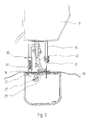
- the sewing material 28 can optionally be pressed against the needle plate 21 and / or the protective window by a slide shoe or roller 38 (FIG. 3) in the area of the protective window 36 from the side of the head part 11.
- the sliding shoe or roller 38 which can be pressed onto the material 28 with a slight pressure of a spring 40, can be fastened, for example, to a holding rod of a presser foot 42. In this embodiment, it can be brought into contact with the sewing material 28 together with the presser foot 42 for the sewing process and then raised again.
- sensors 32 and / or a plurality of sensors 32 working with different technology can also be inserted into the sensor opening 31, for example motion sensors or speed sensors.
- a pair of rollers with at least one electrically drivable first roller 46 (FIG. 5) and a second roller 48 that can be pressed against it can be used as an alternative to the fabric pusher 29, the sewing material 28 between the rollers 46, 48 is passed through.
- the surface of the rollers 46, 48 is made, for example, of rubber or another material that has good adhesive properties with respect to textiles.
- the pair of rollers can be arranged in the sewing direction y behind or in front of the needle insertion opening 23. Alternatively, a pair of rollers can also be arranged behind and in front of the needle insertion opening 23.
- FIG. 6 shows the sewing machine 1 from FIG. 1 with an attached embroidery module 35.
- the embroidery module 35 comprises an embroidery frame 37 for clamping and holding the sewing material 28 and a positioning or movement device 39 which can be driven by two stepping motors (not shown) for moving the embroidery frame 37 in or against the two directions x and y of the sewing plane N.
- the embroidery frame 37 is attached to a frame holder 30 which is movable in the y direction along a first arm 43 of the movement device 39. This first arm 43 in turn can be moved in the x direction along a second arm 45 of the movement device 39.
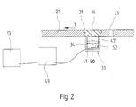
- FIG. 2 shows a longitudinal section through the throat plate 21 in the sewing direction y in the region of the position sensor 33.
- the protective window 36 is, for example, a scratch-resistant sapphire glass or made of a hard, transparent plastic. The depositing of dust or dirt particles is prevented by the flush fit into the sensor opening 31.
- the lens 34 and a substrate 41 arranged below it, for example a printed circuit board, as a carrier of a two-dimensional CCD matrix 50 and a light source 52, for example an LED, are held in a sensor housing 47.
- the position sensor 33, in particular the substrate 41 with the CCD matrix 50 and the light source 52 are connected to sensor electronics 49, which can comprise a processor with a clock rate of more than 10 MHz, for example, and can execute digital image processing algorithms.
- FIG. 7 shows a top view of the throat plate 21 with the sewing material 28 lying thereon during the sewing process in the sewing direction y. In the example shown in FIG.
- the stitch width or the distance between the puncture points 51 of the sewing stitches already carried out in the sewing material 28 is equal to a first actual step size ⁇ y B of the fabric feed through the fabric pushers 29 in the sewing direction y per feed cycle, since after each fabric push -Cycle a sewing stitch was carried out.
- a first actual step size ⁇ y B of the fabric feed through the fabric pushers 29 in the sewing direction y per feed cycle since after each fabric push -Cycle a sewing stitch was carried out.
- several fabric pushing or feed cycles can be carried out before the execution of sewing stitches, in which the actual fabric feed or the first actual step width in sewing direction y is ⁇ y B in each case.
- the first actual step size ⁇ y B of the fabric feed in the sewing direction y is changed by the user of the sewing machine 1 or by the control 13 during the sewing process.
- the first target step sizes ⁇ y A and the first actual step sizes ⁇ y B can take on both positive and negative values.
- the input or specification of a default value or a first target step size ⁇ y A for the material feed in the sewing direction y is symbolically represented on the control 13 in FIG.
- Such a default value can be made, for example, by users of the sewing machine 1 using a scale wheel or menu-controlled via a touch screen.
- the controller 13 can also calculate such default values for first target step sizes ⁇ y A , in particular taking user inputs into account.
- the first thrust variable ⁇ y T likewise symbolically shown in FIG.
- the first thrust variable ⁇ y T can assume negative or positive values, depending on whether a movement backwards or forward in the sewing direction y.
- the values of the first thrust quantity ⁇ y T and the first actual step size ⁇ y B correspond to the value of the first target step size ⁇ y A.
- the first thrust quantity ⁇ y T is somewhat larger than the first nominal step size ⁇ y A , because a certain slippage of the sewing material 28 must be expected with each transport step. It is thereby achieved that the first actual step size ⁇ y B corresponds approximately to the value of the first target step size ⁇ y A for an average sewing material 28.
- a value for the ratio of the first thrust size ⁇ y T to the first desired step size ⁇ y A which is optimal for an average sewing material 28, can be stored in a non-volatile memory of the control 13, with this average sewing material 28 being fed with this first thrust size when the sewing medium is advanced ⁇ y T an actual material feed is achieved by a first actual step size ⁇ y B , which corresponds to the value of the first target step size ⁇ y A.
- the material transport device 27 is designed such that the sewing material 28 can be moved in addition to the sewing direction y in a transverse direction x lying in the vicinity plane N and oriented vertically to the sewing direction y.
- FIG. 9 shows a top view of the throat plate 21 with the sewing material 28 lying thereon during the sewing process with feed movements in the sewing direction y and in the transverse direction x.
- the fabric pushers 29 can also carry out a transport movement in the transverse direction x.
- the material pushers 29 each carry out a transport or feed cycle with a second thrust size ⁇ x T in the transverse direction x on the basis of a second set step size ⁇ x A.
- FIG. 10 shows the cyclical movement of a bar of the presser foot 29 for such a transport cycle.
- the second thrust size ⁇ x T is longer and the dimensions of the bar are shown smaller than they actually are in relation to the stroke movement. Possible positions of the bar during a transport cycle are shown in dotted lines.
- the sewing material 28 is moved in the transverse direction x by a second actual step size ⁇ x B.
- ⁇ x A , ⁇ x T and ⁇ x B can take positive and negative values, which corresponds to movements in and against the transverse direction x.
- the relative coordinates in units of the respective first actual step sizes ⁇ y B in the sewing direction y and the respective second actual step sizes ⁇ x B in the transverse direction x are given between the individual puncture points 51a-51e already carried out.
- the associated individual feed cycles of the fabric pusher 29 in the sewing direction y and in the transverse direction x can be carried out successively one after the other. Alternatively, part of the feed cycles to be carried out between two puncture points 51 can also take place as a combined movement in the sewing direction y and transverse direction x at the same time.
- the first thrust size ⁇ y T is minimal the value of the step size of the stepping motor acting in sewing direction y.
- the second thrust quantity ⁇ x T minimally has the value of the step size of the stepping motor acting in the transverse direction x. If these step sizes are very small, for example less than 0.1 mm, a multiple of these step sizes can also be defined as the first thrust variable ⁇ y T or as the second thrust variable ⁇ x T and stored, for example, in a non-volatile memory of the controller 13 or the embroidery module 35.
- the first thrust sizes ⁇ y T or the second thrust sizes ⁇ x T can also be newly defined for each sewing stitch to be carried out, for example as values of the stitch width in the sewing direction y and in the transverse direction x.
- the actual step sizes ⁇ y B , ⁇ x B can deviate from the associated desired step sizes ⁇ y A , ⁇ x A both during the transport of the sewing material 28 by means of fabric slides 29 and during the transport using the movement device 39 of an embroidery module 35.
- Reasons for this can be, for example, different transport properties depending on the sewing material 28, the sewing position within the sewing material 28 or the transport direction. Forces which act on the sewing material 28 during the sewing process and signs of wear on the sewing machine 1 are further possible causes for changing transport properties. As can be seen from the basic diagram in FIG.
- the first thrust variable ⁇ y T or the second thrust variable ⁇ x T becomes dependent on the first actual step width ⁇ y B of the actual material feed in the sewing direction y or the second actual step width ⁇ x B detected by the position sensor 33 regulated in the transverse direction x.
- a region of the sewing material 28 lying above the protective window 36 (FIG. 2) which for example has the dimensions 5 mm ⁇ 5 mm, is illuminated by the light source 52 and imaged on the CCD matrix 50 via the lens 34.
- the sensor electronics 49 which comprises a digital image processing unit, abbreviated to IPS (Image Processing System) or DSP (Digital Signal Processor)
- the position sensor 33 can, for example, acquire and process 1500 images per second.
- the position sensor 33 is able to recognize the smallest structures or structure differences as well as their position in the recorded image section on the basis of intensity differences within the recorded image section. Due to the change in position of characteristic irregularities in the surface structure of the sewing material 28 and / or due to the change in position of color patterns of the sewing material 28 in immediately successive and / or temporally spaced apart image recordings, the IPS of the position sensor 33 determines relative displacements of the sewing material 28 in the sewing direction y and in the Cross direction x or the corresponding feed speeds. The resolution and accuracy of the position sensor 33 can be further improved by taking into account several image recordings with at least one common structural feature.
- the displacements or changes in position of the sewing material 28 are summed up by the sensor electronics 49, starting from the x and y coordinates of a zero or starting value at the start of the sewing process, and as absolute x and y coordinates of the position or position values in relation to the Starting value provided as an output signal.
- the controller 13 reads the actual feed values of the sewing material 28 determined by the IPS in the x and y directions with respect to the starting value and stores them in a memory of the controller 13
- the feed values can also be transmitted to the controller 13 and stored during the material advancement, for example periodically at the same or changing intervals.
- a sewing step which is characterized by two successive needle sticks, can consequently be broken down in any desired manner into individual target step sizes, for which the actual actual step sizes are then determined by the sensor 32.
- the controller 13 calculates the associated actual material feed, that is to say the first actual step size ⁇ y B or the second actual step size ⁇ x B.
- the zero or start value can be set again and again for each sewing step or feed cycle or a multiple thereof.
- the value transferred from the IPS to the controller 13 is directly the first actual step size ⁇ y B or the second actual step size ⁇ x B, and the difference is omitted.
- the controller 13 now determines the deviation of the associated first target step size ⁇ y A from the determined first actual step size ⁇ y B and stores this value as the first correction value D y .
- the second thrust quantity ⁇ x T is regulated in an analogous manner.
- the controller 13 can correct any deviations detected in the first thrust sizes ⁇ y T or the second thrust sizes ⁇ x T very quickly within only one feed or sewing step.
- the individual target step sizes can be set as desired within a sewing step, so that the thrust sizes ⁇ y T , ⁇ x T can even be regulated within a single sewing step.
- other known control algorithms for controlling the thrust quantities ⁇ y T , ⁇ x T can also be used, in which errors are compensated for and corrected over several feed or sewing steps. This makes it possible to avoid major differences between the stitch widths of two successive sewing stitches as well as unwanted feedback or oscillations of the sewing needle.
- the thrust quantities ⁇ y T , ⁇ x T are set or controlled via stepper motors.
- the stepping motors act directly or indirectly on an adjusting device (not shown) for setting the respective thrust sizes ⁇ y T , ⁇ x T.
- the thrust sizes ⁇ y T , ⁇ x T of these stepper motors are directly adapted.
- the sensor 32 can also be used for the optical recognition of the embroidery hoop if its edge is above the sensor 32. In this way, an embroidery hoop coding for recognizing different hoop types and sizes can be easily replaced.
Landscapes
- Engineering & Computer Science (AREA)
- Textile Engineering (AREA)
- Computer Hardware Design (AREA)
- Microelectronics & Electronic Packaging (AREA)
- Sewing Machines And Sewing (AREA)
Abstract
Description
Alternativ kann zum Sticken von Mustern auch ein Stickrahmen verwendet werden. Anstelle von Stoffschiebern wird zum Bewegen des Nähgutes in der Nähebene ein beispielsweise von zwei Schrittmotoren antreibbarer Stickrahmen eingesetzt, wobei der Stoff oder das Nähgut in diesen Stickrahmen eingespannt ist. Nach der Ausführung eines Nähstiches wird der Stickrahmen mittels der beiden Schrittmotoren derart verschoben, dass die neue Einstichstelle unter die Nähnadel zu liegen kommt.
Für gewisse Nähvorgänge und insbesondere für das Sticken von Mustern ist es von grosser Bedeutung, dass vorgegebene Stichweiten und -richtungen in der Nähebene eingehalten werden. Bei herkömmlichen Näh- und Stickmaschinen können die tatsächlichen Stichweiten und -richtungen allerdings von den an der Maschine eingestellten oder von der Maschinensteuerung errechneten Werten abweichen. Der tatsächliche Stoffvorschub in einer oder zwei Richtungen bei den einzelnen Transportschritten oder -zyklen entspricht nicht den geforderten Vorgabewerten. Solche Abweichungen können systembedingt oder zufällig sein. Abweichungen der tatsächlichen Ist-Stichweiten bzw. Ist-Vorschubweiten von den jeweiligen Soll-Stichweiten bzw. Soll-Vorschubweiten der Stofftransport-Vorrichtung können beispielsweise vom Nähmaschinenmodell oder von den Eigenschaften des Nähgutes bzw. des Stoffes oder von Krafteinwirkungen auf das Nähgut beim Nähen oder Sticken abhängen. Insbesondere der vom Nähgut abhängige Schlupf beim Transportvorgang oder unterschiedliche Transporteigenschaften beim Vor- und Rückwärtstransport des Nähgutes sind dabei von Bedeutung. Abweichungen der Ist-Werte von den Soll-Werten können auch bei Verwendung von Stickrahmen auftreten, beispielsweise, wenn sich der Stoff innerhalb des Stickrahmens verzieht.
Im ersten Fall können bei der Ausführung eines Nähschrittes oder Vorschubzyklus festgestellte Abweichungen des Ist-Vorschubs vom Soll-Vorschub bereits im selben oder im darauf folgenden Nähschritt oder Vorschubzyklus kompensiert werden. Die Kompensation im folgenden Nähschritt bewirkt einen relativ grossen Unterschied zweier aufeinanderfolgender Schrittweiten. Falls der zur Erfassung des Vorschubs eingesetzte Sensor eine deutlich höhere Abtastrate aufweist, als die für die Ausführung des Nähschrittes benötigte Zeit, kann die Regelung der Vorschubgrösse sogar während der Ausführung dieses Nähschrittes erfolgen. Die Ist-Werte stimmen in diesem Fall im Rahmen der Genauigkeit der Regelung für jeden Nähschritt mit den Soll-Werten überein. Diese Variante der Regelung der Vorschubgrösse ist insbesondere bei Stofftransportsystemen von Bedeutung, deren Antrieb unabhängig vom Hauptantrieb der Nadelstange erfolgt.
Im zweiten Fall erfolgt die Kompensation der festgestellten Abweichung verteilt über mehrere Nähschritte oder Vorschubzyklen, wodurch sich im Mittel nur kleine Unterschiede zwischen den einzelnen Stichweiten ergeben.
Das Verfahren kann zur Regelung der Vorschubgrössen bei Vor- und/oder Rückwärtsbewegungen des Nähgutes in einer oder zwei Dimensionen der Nähebene genutzt werden.
In einer bevorzugten Ausgestaltung der Erfindung können vom Sensor festgestellte Abweichungen des tatsächlichen Stoffvorschubes in Nährichtung und in einer vertikal zur Nährichtung stehenden Querrichtung vom Sensor erfasst werden. Beim Nähen in Nährichtung können vom Sensor erfasste Abweichungen in Nährichtung und/oder in Querrichtung durch Beeinflussung der Vorschubgrössen in Nährichtung und/oder Querrichtung ausgeglichen werden. Dasselbe gilt für Nähvorgänge in Querrichtung.
Das erfindungsgemässe Verfahren und die erfindungsgemässe Vorrichtung eignen sich zur Regelung zyklisch arbeitender, mit dem Hauptantrieb für die Nadelstange gekoppelter Vorschubmittel. Das Verfahren und die Vorrichtung können auch zur Regelung des Stofftransportes in Nährichtung und/oder Querrichtung mit unabhängigen, nicht mit dem Hauptantrieb gekoppelten Antrieben eingesetzt werden. Solche Antriebe können beispielsweise die Schrittmotoren eines Stickrahmens oder elektromotorische Walzenantriebe sein.
- Figur 1
- eine perspektivische Ansicht einer Nähmaschine mit partiell aufgeschnittenem Gehäuse und mit einem in die Stichplatte eingebauten Bildsensor,
- Figur 2
- einen Längsschnitt durch die Stichplatte im Bereich des Positionssensors,
- Figur 3
- einen Querschnitt durch den Unterarm und durch einen das Nähgut an ein Schutzfenster andrückenden, am Nähfuss befestigten Roller,
- Figur 4
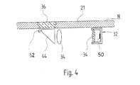
- einen Querschnitt der Stichplatte mit darunter angeordneten Verbindungsmitteln zum Sensor,
- Figur 5
- eine Seitenansicht eines Teils der Nähmaschine in Querrichtung mit zwei aufgeschnittenen Walzenpaaren für den Transport des Nähgutes in Nährichtung.
- Figur 6
- die in Figur 1 dargestellte Nähmaschine mit angebautem Stickrahmen,
- Figur 7
- eine Aufsicht auf die Stichplatte mit darauf aufliegendem Nähgut während des Nähvorgangs in Nährichtung,
- Figur 8
- eine schematisch dargestellte Ermittlung der Schubgrösse ΔyT durch die Steuerung 13,
- Figur 9
- eine Aufsicht auf die Stichplatte mit darauf aufliegendem Nähgut während des Näh- oder Stickvorgangs in Näh- und Querrichtung,
- Figur 10
- ein schematisch dargestellter zyklischer Bewegungsablauf eines Stoffschiebers mit einer Schubgrösse ΔxT in Querrichtung,
- Figur 11
- ein Prinzipschema der Regelung von Schubgrössen anhand von Messgrössen des Positionssensors,
Zum Transportieren des Nähgutes 28 in Nährichtung y kann alternativ zum Stoffschieber 29 auch ein Walzenpaar mit mindestens einer elektrisch antreibbaren ersten Walze 46 (Fig. 5)und einer an diese anpressbaren zweiten Walze 48 eingesetzt sein, wobei das Nähgut 28 zwischen den Walzen 46,48 hindurchgeführt wird. Die Oberfläche der Walzen 46,48 ist beispielsweise aus Gummi oder einem anderen Material gefertigt, das in Bezug auf Textilien gute Hafteigenschaften aufweist. Das Walzenpaar kann in Nährichtung y hinter oder vor der Nadeleinstichöffnung 23 angeordnet sein. Alternativ kann auch je ein Walzenpaar hinter und vor der Nadeleinstichöffnung 23 angeordnet sein. Der Vorteil solcher Walzenantriebe liegt in ihrer Unabhängigkeit vom Hauptantrieb für die Nadelstange 15 und in der Möglichkeit beliebig grosser Stoffvorschübe in und entgegen der Nährichtung y.
In Figur 6 ist die Nähmaschine 1 aus Figur 1 mit einem angebauten Stickmodul 35 dargestellt. Das Stickmodul 35 umfasst einen Stickrahmen 37 zum Einspannen und Halten des Nähgutes 28 und eine von zwei (nicht dargestellten) Schrittmotoren antreibbare Positionier- oder Bewegungsvorrichtung 39 zum Bewegen des Stickrahmens 37 in oder entgegen der zwei Richtungen x und y der Nähebene N. Der Stickrahmen 37 ist an einem Rahmenhalter 30 befestigt, welcher entlang eines ersten Arms 43 der Bewegungsvorrichtung 39 in y-Richtung bewegbar ist. Dieser erste Arm 43 wiederum ist entlang eines zweiten Arms 45 der Bewegungsvorrichtung 39 in x-Richtung bewegbar. Das Nähgut 28 ist im Stickrahmen 37 so eingespannt, dass es auf der Nähebene N aufliegt.
Figur 2 zeigt einen Längsschnitt durch die Stichplatte 21 in Nährichtung y im Bereich des Positionssensors 33. Das Schutzfenster 36 ist beispielsweise ein kratzfestes Saphirglas oder aus einem harten, transparenten Kunststoff gefertigt. Durch die bündige Einpassung in die Sensoröffnung 31 wird die Ablagerung von Staub oder Schmutzpartikeln verhindert. Die Linse 34 und ein darunter angeordnetes Substrat 41, beispielsweise eine Leiterplatte, als Träger einer zweidimensionalen CCD-Matrix 50 und einer Lichtquelle 52, beispielsweise einer LED, sind in einem Sensorgehäuse 47 gehalten. Der Positionssensor 33, insbesondere das Substrat 41 mit der CCD-Matrix 50 und der Lichtquelle 52 sind mit einer Sensorelektronik 49 verbunden, die einen Prozessor von beispielsweise mehr als 10 MHz Taktrate umfassen kann und digitale Bildverarbeitungs-Algorithmenausführen kann.
In Figur 7 ist eine Aufsicht die Stichplatte 21 mit darauf aufliegendem Nähgut 28 während des Nähvorgangs in Nährichtung y dargestellt. Die Stichweite oder der Abstand der Einstichstellen 51 der bereits ausgeführten Nähstiche im Nähgut 28 ist im in Figur 7 dargestellten Beispiel gleich einer ersten Ist-Schrittweite ΔyB des Stoff-Vorschubs durch die Stoffschieber 29 in Nährichtung y pro Vorschub-Zyklus, da nach jedem Stoffschiebe-Zyklus jeweils ein Nähstich ausgeführt wurde. Grundsätzlich können vor der Ausführung von Nähstichen auch mehrere Stoffschiebeoder Vorschub-Zyklen ausgeführt werden, bei denen der tatsächliche Stoff-Vorschub bzw. die erste Ist-Schrittweite in Nährichtung y jeweils ΔyB beträgt. Es ist auch möglich, dass die erste Ist-Schrittweite ΔyB des Stoff-Vorschubs in Nährichtung y während des Nähvorgangs durch den Benutzer der Nähmaschine 1 oder durch die Steuerung 13 verändert wird. Bei jenen Ausgestaltungen der Nähmaschine 1, die einen Stoffvorschub sowohl in als auch entgegen der Nährichtung y zulassen, können die ersten Soll-Schrittweiten ΔyA und die ersten Ist-Schrittweiten ΔyB sowohl positive als auch negative Werte annehmen. Symbolisch ist in Figur 8 die Eingabe oder Vorgabe eines Vorgabewertes bzw. einer ersten Soll-Schrittweite ΔyA für den Stoffvorschub in Nährichtung y an der Steuerung 13 dargestellt. Ein solcher Vorgabewert kann beispielsweise durch Benutzer der Nähmaschine 1 mittels eines Skalenrades oder menügesteuert über einen Touch-Screen erfolgen. Alternativ oder zusätzlich kann die Steuerung 13 solche Vorgabewerte für erste Soll-Schrittweiten ΔyA auch berechnen, insbesondere unter Berücksichtigung von Benutzereingaben. Die in Figur 8 ebenfalls symbolisch dargestellte erste Schubgrösse ΔyT entspricht der auf das Nähgut 28 in Nährichtung y wirkenden Vorschubbewegung der Stofftransportvorrichtung 27, insbesondere der Stoffschieber 29. Die erste Schubgrösse ΔyT kann negative oder positive Werte annehmen, je nachdem, ob eine Bewegung rückwärts oder vorwärts in Nährichtung y erfolgt. Im Idealfall entsprechen die Werte der ersten Schubgrösse ΔyT und der ersten Ist-Schrittweite ΔyB dem Wert der ersten Soll-Schrittweite ΔyA. In Wirklichkeit ist die erste Schubgrösse ΔyT aber etwas grösser als die erste Soll-Schrittweite ΔyA, weil bei jedem Transportschritt mit einem gewissen Schlupf des Nähgutes 28 gerechnet werden muss. Dadurch wird erreicht, dass die erste Ist-Schrittweite ΔyB bei einem durchschnittlichen Nähgut 28 ungefähr dem Wert der ersten Soll-Schrittweite ΔyA entspricht. Zu diesem Zweck kann beispielsweise in einem nichtflüchtigen Speicher der Steuerung 13 ein Wert für das für ein durchschnittliches Nähgut 28 optimale Verhältnis der ersten Schubgrösse ΔyT zur ersten Soll-Schrittweite ΔyA hinterlegt sein, wobei bei einem Vorschub dieses durchschnittlichen Nähgutes 28 mit dieser ersten Schubgrösse ΔyT ein tatsächlicher Stoffvorschub um eine erste Ist-Schrittweite ΔyB erreicht wird, die dem Wert der ersten Soll-Schrittweite ΔyA entspricht.
In Figur 9 ist eine Aufsicht auf die Stichplatte 21 mit darauf aufliegendem Nähgut 28 während des Nähvorgangs mit Vorschubbewegungen in Nährichtung y und in Querrichtung x dargestellt. In analoger Weise zur Transportbewegung in Nährichtung y können die Stoffschieber 29 zusätzlich auch eine Transportbewegung in Querrichtung x ausführen. Dabei führen die Stoffschieber 29 aufgrund einer zweiten Soll-Schrittweite ΔxA jeweils einen Transport- oder Vorschubzyklus mit einer zweiten Schubgrösse ΔxT in Querrichtung x aus.
In Figur 10 ist die zyklische Bewegung eines Balkens des Nähfusses 29 für einen solchen Transportzyklus dargestellt. Zur besseren Erkennbarkeit ist die zweite Schubgrösse ΔxT länger und sind die Abmessungen des Balkens kleiner dargestellt, als sie im Verhältnis zur Hubbewegung tatsächlich sind. Mögliche Positionen des Balkens während eines Transportzyklus sind gepunktet eingezeichnet.
Das Nähgut 28 wird jeweils um eine zweite Ist-Schrittweite ΔxB in Querrichtung x bewegt. Selbstverständlich können ΔxA, ΔxT und ΔxB positive und negative Werte annehmen, was Bewegungen in und entgegen der Querrichtung x entspricht. Wie aus Figur 9 ersichtlich, sind zwischen den einzelnen, bereits ausgeführten Einstichstellen 51a - 51e die relativen Koordinaten in Einheiten der jeweiligen ersten Ist-Schrittweiten ΔyB in Nährichtung y und der jeweiligen zweiten Ist-Schrittweiten ΔxB in Querrichtung x angegeben. Die zugehörigen einzelnen Vorschubzyklen der Stoffschieber 29 in Nährichtung y und in Querrichtung x können aufeinanderfolgend einer nach dem anderen ausgeführt werden. Alternativ kann auch ein Teil der zwischen zwei Einstichstellen 51 auszuführenden Vorschubzyklen als kombinierte Bewegung gleichzeitig in Nährichtung y und Querrichtung x erfolgen.
Wie aus dem Prinzipschema in Figur 11 erkennbar, wird die erste Schubgrösse ΔyT bzw. die zweite Schubgrösse ΔxT in Abhängigkeit der vom Positionssensor 33 erfassten ersten Ist-Schrittweite ΔyB des tatsächlichen Stoffvorschubs in Nährichtung y bzw. der zweiten Ist-Schrittweite ΔxB in Querrichtung x geregelt. Ein über dem Schutzfenster 36 (Fig. 2) liegender Bereich des Nähgutes 28, der beispielsweise die Abmessungen 5mm x 5mm hat, wird von der Lichtquelle 52 beleuchtet und über die Linse 34 auf die CCD-Matrix 50 abgebildet. In Verbindung mit der Sensorelektronik 49, die eine digitale Bildverarbeitungseinheit, kurz IPS (Image Processing System) oder DSP (Digital Signal Processor) genannt, umfasst, kann der Positionssensor 33 beispielsweise 1500 Bilder pro Sekunde erfassen und verarbeiten. Der Positionssensor 33 ist in der Lage, anhand von Intensitätsunterschieden innerhalb des erfassten Bildausschnittes kleinste Strukturen oder Strukturunterschiede sowie deren Lage im erfassten Bildausschnitt zu erkennen. Aufgrund der Lageänderung charakteristischer Unregelmässigkeiten in der Oberflächenstruktur des Nähgutes 28 und/oder aufgrund der Lageänderung von Farbmustern des Nähgutes 28 in direkt aufeinanderfolgenden und/oder zeitlich weiter auseinanderliegenden Bildaufnahmen ermittelt das IPS des Positionssensors 33 relative Verschiebungen des Nähgutes 28 in der Nährichtung y und in der Querrichtung x bzw. die entsprechenden Vorschubgeschwindigkeiten. Durch Berücksichtigung mehrerer Bildaufnahmen mit mindestens einem gemeinsamen Strukturmerkmal können Auflösung und Genauigkeit des Positionssensors 33 weiter verbessert werden. Vorzugsweise werden die Verschiebungen oder Lageänderungen des Nähgutes 28 durch die Sensorelektronik 49, ausgehend von den x- und y- Koordinaten eines Nulloder Startwertes beim Beginn des Nähvorgangs, aufsummiert und als absolute x- und y- Koordinaten der Lage- oder Positionswerte in Bezug auf den Startwert als Ausgangssignal bereitgestellt.
Wenn das Nähgut 28 nach der Ausführung von Nähstichen oder Vorschubzyklen still steht, liest die Steuerung 13 jeweils die vom IPS ermittelten tatsächlichen Vorschubwerte des Nähgutes 28 in x- und y- Richtung in Bezug auf den Startwert ein und speichert sie in einem Speicher der Steuerung 13. Alternativ, wenn der Sensor 32 eine genügend hohe zeitliche Abtastrate aufweist, können die Vorschubwerte auch während des Stoffvorschubs an die Steuerung 13 übermittelt und gespeichert werden, beispielsweise periodisch in zeitlich gleichen oder ändernden Intervallen. Ein Nähschritt, der durch zwei aufeinanderfolgende Nadelstiche charakterisiert ist, kann demzufolge in beliebiger Weise in einzelne Soll-Schrittweiten zerlegt werden, für die dann die tatsächlichen Ist-Schrittweiten vom Sensor 32 ermittelt werden.
Durch Differenzbildung unmittelbar nacheinander gespeicherter korrespondierender Werte berechnet die Steuerung 13 den zugehörigen tatsächlichen Stoffvorschub, also die erste Ist-Schrittweite ΔyB bzw. die zweite Ist-Schrittweite ΔxB.
Alternativ kann der Null- oder Startwert für jeden Nähschritt oder Vorschubzyklus oder ein Vielfaches davon immer wieder neu festgelegt werden. Der vom IPS an die Steuerung 13 übergebene Wert ist in diesem Fall direkt die erste Ist-Schrittweite ΔyB bzw. die zweite Ist-Schrittweite ΔxB und die Differenzbildung entfällt.
Alternativ können auch andere bekannte Regelalgorithmen zum Regeln der Schubgrössen ΔyT,ΔxT verwendet werden, bei denen ein Ausgleich und eine Korrektur von Fehlern über mehrere Vorschub- oder Nähschritte erfolgt. Dadurch lassen sich grössere Unterschiede zwischen den Stichweiten zweier aufeinanderfolgender Nähstiche sowie unerwünschte Rückkopplungen oder Oszillationen der Nähnadel vermeiden.
Der Sensor 32 kann im übrigen auch zur optischen Erkennung von Stickrahmen genutzt werden, wenn sich dessen Rand über dem Sensor 32 befindet. So kann auf einfache Art eine Stickrahmencodierung zur Erkennung unterschiedlicher Rahmenarten und -grössen ersetzt werden.
Claims (11)
- Verfahren zum Regeln des Stofftransportes bei einer Näh- oder Stickmaschine (1) mit mindestens einer Stofftransportvorrichtung (27) zum Transportieren des Nähgutes (28) in mindestens einer Richtung um jeweils eine Soll-Schrittweite (ΔyA; ΔxA), wobei die Soll-Schrittweite (ΔyA; ΔxA) einstell- oder von einer Steuerung (13) berechenbar ist und mindestens eine Schubgrösse (ΔyT; ΔxT) der Stofftransportvorrichtung (27) zum Transportieren des Nähgutes (28) beeinflusst, dadurch gekennzeichnet, dass mindestens eine Ist-Schrittweite (ΔyB; ΔxB) von mindestens einem Sensor (32) erfasst wird, und dass die Steuerung (13) die Schubgrösse (ΔyT; ΔxT) in Abhängigkeit der Ist-Schrittweiten (ΔyB; ΔxB) derart regelt, dass sich die Abweichungen der Ist-Schrittweiten (ΔyB; ΔxB) von den jeweiligen Soll-Schrittweiten (ΔyA; ΔxA) im Mittel über einen oder mehrere aufeinanderfolgende Nähschritte oder Vorschubzyklen kompensieren.
- Verfahren nach Anspruch 1, wobei die Stofftransportvorrichtung (27) zum Transportieren des Nähgutes (28) in einer Nährichtung (y) um jeweils erste Soll-Schrittweiten (ΔyA) und in einer Querrichtung(x) um jeweils zweite Soll-Schrittweiten (ΔxA) geeignet ist, und wobei die erste Soll-Schrittweite (ΔyA) und die zweite Soll-Schrittweite (ΔxA) einstell- oder von einer Steuerung (13) berechenbar sind und eine erste Schubgrösse (ΔyT) und eine zweite Schubgrösse (ΔxT) der Stofftransportvorrichtung (27) zum Transportieren des Nähgutes (28) in Nährichtung (y) und in Querrichtung (x) beeinflussen, dadurch gekennzeichnet, dass die erste Ist-Schrittweite (ΔyB) und die zweite Ist-Schrittweite (ΔxB) von dem oder den Sensoren (32) erfasst werden, und dass die Steuerung (13) die erste Schubgrösse (ΔyT) und die zweite Schubgrösse (ΔxT) in Abhängigkeit von ersten Ist-Schrittweiten (ΔyB) und von zweiten Ist-Schrittweiten (ΔxB) derart regelt, dass sich die Abweichungen der ersten Ist-Schrittweiten (ΔyB) und der zweiten Ist-Schrittweiten (ΔxB) von den jeweiligen Soll-Schrittweiten (ΔyA; ΔxA) im Mittel über einen oder mehrere aufeinanderfolgende Nähschritte oder Vorschubzyklen kompensieren.
- Verfahren nach einem der Ansprüche 1 oder 2, dadurch gekennzeichnet, dass die Steuerung (13) die Sensorsignale periodisch oder im Rhythmus einzelner oder mehrerer Vorschubzyklen oder Nähschritte als Daten einliest und die erste Ist-Schrittweite (ΔyB) und/oder die zweite Ist-Schrittweite (ΔxB) bzw. die entsprechenden Vorschubgeschwindigkeiten ermittelt.
- Verfahren nach einem der Ansprüche 1 bis 3, dadurch gekennzeichnet, dass von dem oder den Sensoren (32) erfasste erste Ist-Schrittweiten (ΔyB) und/oder zweite Ist-Schrittweiten (ΔxB) und/oder Abweichungen dieser Ist-Schrittweiten (ΔyB; ΔxB), von den jeweiligen Soll-Schrittweiten (ΔyA; ΔxA), in einem Speicher gespeichert oder aufsummiert werden.
- Verfahren nach einem der Ansprüche 1 bis 4, dadurch gekennzeichnet, dass eine von dem oder den Sensoren (32) erfasste zufällige oder systembedingte Abweichung der ersten Ist-Schrittweite (ΔyB) und/oder der zweiten Ist-Schrittweite (ΔxB) von der jeweiligen Soll-Schrittweite (ΔyA; ΔxA) über einen oder mehrere Nähschritte oder Vorschubzyklen durch Ändern oder Regeln der zugehörigen Schubgrössen (ΔyT; ΔxT) derart kompensiert wird, dass sich die Abweichungen im Mittel über einen oder mehrere Nähschritte oder Vorschubzyklen gegenseitig aufheben.
- Vorrichtung zur Durchführung des Verfahrens nach einem der Ansprüche 1 bis 5, dadurch gekennzeichnet, dass der oder die Sensoren (32) zur Auflösung einer Messgrösse in mindestens einer räumlichen Dimension ausgebildet sind.
- Vorrichtung nach Anspruch 6, dadurch gekennzeichnet, dass der oder die Sensoren (32) eine parallel zur Nährichtung (y) ausgerichtete CCD-Zeile oder eine CCD-Matrix (50) oder eine Mikrokamera mit einer Bildverarbeitungseinheit zum Erfassen und Verarbeiten eines ein- oder zweidimensionalen Bildbereiches umfassen.
- Vorrichtung nach einem der Ansprüche 6 oder 7, dadurch gekennzeichnet, dass der oder die Sensoren (32) oder Verbindungsmittel zu dem oder den Sensoren (32) mindestens teilweise in einem Schacht 19 unterhalb einer Stichplatte (21) der Näh- oder Stickmaschine (1) angeordnet sind.
- Vorrichtung nach einem der Ansprüche 6 bis 8, dadurch gekennzeichnet, dass eine Sensoröffnung (33) im Bereich einer Nadeleinstichöffnung (23) in die Stichplatte (21) eingelassen ist, dass diese Sensoröffnung (33) durch ein Schutzfenster (36) abgedeckt ist, und dass der oder die Sensoren (32) oder die Verbindungsmittel zu dem oder den Sensoren (32) mindestens teilweise unter diesem Schutzfenster (36) angeordnet sind.
- Vorrichtung nach Anspruch 9, dadurch gekennzeichnet, dass das Nähgut (28) im Bereich des Schutzfensters (36) durch einen Gleitschuh oder Roller (38) auf die Stichplatte (21) oder das Schutzfenster (36) aufpressbar ist.
- Vorrichtung nach einem der Ansprüche 9 oder 10, dadurch gekennzeichnet, dass unter dem Schutzfenster (36) eine Lichtquelle (52) angeordnet ist.
Applications Claiming Priority (2)
| Application Number | Priority Date | Filing Date | Title |
|---|---|---|---|
| CH23172001 | 2001-12-19 | ||
| CH23172001 | 2001-12-19 |
Publications (3)
| Publication Number | Publication Date |
|---|---|
| EP1321556A2 true EP1321556A2 (de) | 2003-06-25 |
| EP1321556A3 EP1321556A3 (de) | 2004-12-15 |
| EP1321556B1 EP1321556B1 (de) | 2006-01-04 |
Family
ID=4568548
Family Applications (1)
| Application Number | Title | Priority Date | Filing Date |
|---|---|---|---|
| EP02405896A Expired - Lifetime EP1321556B1 (de) | 2001-12-19 | 2002-10-21 | Verfahren und Vorrichtung zum Regeln des Stofftransportes bei einer Näh- oder Stickmaschine |
Country Status (4)
| Country | Link |
|---|---|
| US (2) | US6871606B2 (de) |
| EP (1) | EP1321556B1 (de) |
| AT (1) | ATE315120T1 (de) |
| DE (1) | DE50205513D1 (de) |
Cited By (5)
| Publication number | Priority date | Publication date | Assignee | Title |
|---|---|---|---|---|
| EP1997945A1 (de) * | 2007-05-31 | 2008-12-03 | JUKI Corporation | Knopflochmaschine |
| EP2045386A1 (de) | 2007-10-02 | 2009-04-08 | Dürkopp Adler AG | Nähmaschine |
| CN101501263B (zh) * | 2006-08-17 | 2012-07-04 | 兄弟工业株式会社 | 可编程电子缝纫机和可编程电子缝纫机的控制装置 |
| CN107059260A (zh) * | 2016-02-10 | 2017-08-18 | Juki株式会社 | 缝纫机 |
| CN121670730A (zh) * | 2026-02-11 | 2026-03-17 | 洛阳锐安数控机床有限公司 | 一种基于硬度参数的柔性夹持系统及方法 |
Families Citing this family (47)
| Publication number | Priority date | Publication date | Assignee | Title |
|---|---|---|---|---|
| JP2004008496A (ja) * | 2002-06-07 | 2004-01-15 | Pentax Corp | ゴーグル |
| CN1759215B (zh) * | 2003-02-12 | 2012-01-04 | 拉尔夫·J·柯纳 | 缝被褥的方法及设备 |
| US20040212803A1 (en) * | 2003-04-22 | 2004-10-28 | Sultex Ag | Measuring device for movements on a weaving machine |
| US20050145149A1 (en) * | 2003-10-26 | 2005-07-07 | David Hooke | Electronic Stitch Length Regulator for Home Sewing Machines |
| JP2007513656A (ja) * | 2003-12-15 | 2007-05-31 | フリツツ・ゲガウフ・アクチエンゲゼルシヤフト・ベルニナ・ネーマシイネンフアブリーク | ミシンにおける針の運動を制御するための方法及び装置 |
| US7373891B2 (en) * | 2004-05-14 | 2008-05-20 | Koerner Ralph J | Quilting method and apparatus using frame with motion detector |
| CH697501B1 (de) * | 2004-05-28 | 2008-11-14 | Bernina Int Ag | Vorrichtung und Verfahren zum Erfassen und Verarbeiten von Messgrössen bei einer Nähmaschine. |
| US20060112866A1 (en) * | 2004-12-01 | 2006-06-01 | Pfeifer Thomas A | Stitch regulator for a sewing machine |
| EP1734166A1 (de) * | 2005-06-17 | 2006-12-20 | Fritz Gegauf AG | Verfahren und Vorrichtung zum Erzeugen von Nähdaten |
| EP1739222B1 (de) * | 2005-06-21 | 2008-04-02 | BERNINA International AG | Verfahren und Vorrichtung zur Minimierung von Einstichfehlern bei Stickvorrichtungen |
| GB2431480B (en) * | 2005-10-20 | 2011-08-10 | Vsm Group Ab | Embroidery data generation |
| EP1811073A2 (de) * | 2006-01-18 | 2007-07-25 | BERNINA International AG | Nähmaschine und Verfahren zum Erfassen von Bewegungen bei Nähmaschinen |
| JP2007244463A (ja) * | 2006-03-14 | 2007-09-27 | Brother Ind Ltd | ミシンの布保持枠移送装置 |
| JP4974044B2 (ja) * | 2006-03-23 | 2012-07-11 | ブラザー工業株式会社 | 刺繍縫製可能なミシン |
| JP4927482B2 (ja) * | 2006-09-05 | 2012-05-09 | Juki株式会社 | ミシン |
| JP2008079998A (ja) * | 2006-09-28 | 2008-04-10 | Brother Ind Ltd | ミシン |
| SE529489C2 (sv) * | 2006-11-28 | 2007-08-21 | Vsm Group Ab | Symaskin med stor stygnbredd |
| JP2008212289A (ja) * | 2007-03-01 | 2008-09-18 | Brother Ind Ltd | ミシン及びミシン制御プログラム |
| JP2008228961A (ja) * | 2007-03-20 | 2008-10-02 | Brother Ind Ltd | ミシン及びミシン制御プログラム |
| JP2009011478A (ja) * | 2007-07-03 | 2009-01-22 | Brother Ind Ltd | ミシン及びミシンモータ制御プログラム |
| JP5315705B2 (ja) * | 2008-01-24 | 2013-10-16 | ブラザー工業株式会社 | ミシン |
| JP2009174981A (ja) * | 2008-01-24 | 2009-08-06 | Brother Ind Ltd | ミシン |
| JP2009189626A (ja) * | 2008-02-15 | 2009-08-27 | Brother Ind Ltd | ミシン |
| US8265346B2 (en) | 2008-11-25 | 2012-09-11 | De La Rue North America Inc. | Determining document fitness using sequenced illumination |
| US8780206B2 (en) * | 2008-11-25 | 2014-07-15 | De La Rue North America Inc. | Sequenced illumination |
| US20100186646A1 (en) * | 2009-01-27 | 2010-07-29 | Gammill, Inc. | Stitch quality monitoring system |
| US8245656B2 (en) * | 2009-02-12 | 2012-08-21 | Brother Kogyo Kabushiki Kaisha | Sewing machine, computer readable medium storing thread tension adjustment program for sewing machine, and thread tension evaluation unit |
| US8749767B2 (en) * | 2009-09-02 | 2014-06-10 | De La Rue North America Inc. | Systems and methods for detecting tape on a document |
| CN102277696B (zh) * | 2010-06-09 | 2015-03-11 | Vsm集团股份公司 | 送料器移动补偿 |
| JP2012187345A (ja) * | 2011-03-14 | 2012-10-04 | Brother Ind Ltd | ミシン |
| US9115451B2 (en) | 2011-06-13 | 2015-08-25 | Handi Quilter, Inc. | System and method for controlling stitching using a movable sensor |
| JP2013188263A (ja) * | 2012-03-12 | 2013-09-26 | Brother Ind Ltd | ミシン |
| JP2013188265A (ja) * | 2012-03-12 | 2013-09-26 | Brother Ind Ltd | ミシン |
| JP2013188262A (ja) | 2012-03-12 | 2013-09-26 | Brother Ind Ltd | ミシン |
| JP5605384B2 (ja) * | 2012-03-12 | 2014-10-15 | ブラザー工業株式会社 | 刺繍装置 |
| JP2014008073A (ja) * | 2012-06-27 | 2014-01-20 | Brother Ind Ltd | ミシン |
| US9053596B2 (en) | 2012-07-31 | 2015-06-09 | De La Rue North America Inc. | Systems and methods for spectral authentication of a feature of a document |
| US9315933B1 (en) * | 2013-03-15 | 2016-04-19 | John D. Martelli | Stitch regulation apparatus and method |
| US9840797B2 (en) * | 2014-03-12 | 2017-12-12 | Abm International, Inc. | Method, apparatus, and computer-readable medium for stitching |
| CN107109746B (zh) | 2014-08-01 | 2020-05-05 | 环球仪器公司 | 缝制装置、系统与方法 |
| US10179961B2 (en) * | 2015-06-08 | 2019-01-15 | Conrad Industries, Inc. | Embroidery production monitoring system |
| TR201515464A2 (tr) | 2015-12-04 | 2016-06-21 | Goekhan Uenlue %10 | Dikiş makinelerine takılan elektronik kontrol sistemi |
| JP6860294B2 (ja) * | 2016-04-26 | 2021-04-14 | 蛇の目ミシン工業株式会社 | 刺繍模様連結データ生成装置、刺繍模様連結データ生成方法、プログラムおよび縫製システム |
| US10982365B2 (en) * | 2016-06-08 | 2021-04-20 | One Sciences, Inc. | Multi-patch multi-view system for stitching along a predetermined path |
| US11015276B2 (en) | 2019-02-04 | 2021-05-25 | Handi Quilter, Inc. | Multi-sensor sewing machine with automatic needle speed adjustment |
| USD1069854S1 (en) * | 2022-03-25 | 2025-04-08 | Brother Industries, Ltd. | Embroidery machine |
| US20250347043A1 (en) * | 2024-05-08 | 2025-11-13 | Bernina International Ag | Machine for sewing, embroidery or quilting |
Family Cites Families (12)
| Publication number | Priority date | Publication date | Assignee | Title |
|---|---|---|---|---|
| DD160751A3 (de) * | 1981-04-06 | 1984-02-29 | Textima Veb K | Schaltungsanordnung zum automatischen naehen |
| CA1201021A (en) * | 1983-06-09 | 1986-02-25 | Peter B.S. Shim | Fabric feeder mechanism for sewing machine |
| JPS625388A (ja) * | 1985-06-29 | 1987-01-12 | ブラザー工業株式会社 | ミシンにおける布端部の定寸縫い装置 |
| DE8520285U1 (de) * | 1985-07-13 | 1990-01-04 | Pfaff Industriemaschinen Gmbh, 6750 Kaiserslautern | Vorrichtung zum Messen und Regeln der Vorschubgröße an einer Nähmaschine |
| ES8801002A1 (es) | 1985-07-13 | 1987-12-01 | Pfaff Ind Masch | Procedimiento y dispositivo para determinar la magnitud de avance de al menos una capa de una pieza de trabajo en una maquina de coser. |
| JPS62189087A (ja) * | 1986-02-15 | 1987-08-18 | ブラザー工業株式会社 | 柄合わせ縫製を行うためのミシン |
| JPS63125292A (ja) * | 1986-11-15 | 1988-05-28 | ブラザー工業株式会社 | ミシンの柄合わせ装置 |
| JPH01256997A (ja) * | 1988-04-06 | 1989-10-13 | Brother Ind Ltd | 柄合わせミシン |
| JP3170238B2 (ja) * | 1997-03-24 | 2001-05-28 | 洋 古舘 | 縫製システム及び縫製方法 |
| JP2001334094A (ja) * | 2000-05-26 | 2001-12-04 | Janome Sewing Mach Co Ltd | 刺繍縫いミシン |
| CN1759215B (zh) | 2003-02-12 | 2012-01-04 | 拉尔夫·J·柯纳 | 缝被褥的方法及设备 |
| DE10306775B3 (de) * | 2003-02-18 | 2004-08-05 | Sunstar Precision Co., Ltd. | Vorrichtung und Verfahren für das Steuern der Position eines Stickrahmens |
-
2002
- 2002-10-21 DE DE50205513T patent/DE50205513D1/de not_active Expired - Lifetime
- 2002-10-21 EP EP02405896A patent/EP1321556B1/de not_active Expired - Lifetime
- 2002-10-21 AT AT02405896T patent/ATE315120T1/de not_active IP Right Cessation
- 2002-12-19 US US10/325,775 patent/US6871606B2/en not_active Expired - Lifetime
-
2004
- 2004-12-30 US US11/026,858 patent/US6994042B2/en not_active Expired - Lifetime
Cited By (6)
| Publication number | Priority date | Publication date | Assignee | Title |
|---|---|---|---|---|
| CN101501263B (zh) * | 2006-08-17 | 2012-07-04 | 兄弟工业株式会社 | 可编程电子缝纫机和可编程电子缝纫机的控制装置 |
| EP1997945A1 (de) * | 2007-05-31 | 2008-12-03 | JUKI Corporation | Knopflochmaschine |
| EP2045386A1 (de) | 2007-10-02 | 2009-04-08 | Dürkopp Adler AG | Nähmaschine |
| CN101403169B (zh) * | 2007-10-02 | 2012-12-12 | 杜尔克普—阿德勒股份公司 | 缝纫机 |
| CN107059260A (zh) * | 2016-02-10 | 2017-08-18 | Juki株式会社 | 缝纫机 |
| CN121670730A (zh) * | 2026-02-11 | 2026-03-17 | 洛阳锐安数控机床有限公司 | 一种基于硬度参数的柔性夹持系统及方法 |
Also Published As
| Publication number | Publication date |
|---|---|
| EP1321556B1 (de) | 2006-01-04 |
| US20030131773A1 (en) | 2003-07-17 |
| US6994042B2 (en) | 2006-02-07 |
| DE50205513D1 (de) | 2006-03-30 |
| US20050115482A1 (en) | 2005-06-02 |
| ATE315120T1 (de) | 2006-02-15 |
| EP1321556A3 (de) | 2004-12-15 |
| US6871606B2 (en) | 2005-03-29 |
Similar Documents
| Publication | Publication Date | Title |
|---|---|---|
| EP1321556B1 (de) | Verfahren und Vorrichtung zum Regeln des Stofftransportes bei einer Näh- oder Stickmaschine | |
| DE3346163C1 (de) | Verfahren zum mustergerechten Zusammennaehen von Stoffteilen | |
| EP0102524B1 (de) | Antriebs- und Steuervorrichtung für Nähmaschinen, Nähautomaten und dergleichen | |
| DE4026250C2 (de) | ||
| DE2729509B2 (de) | Vorrichtung zum Schneiden einer textlien, Querstreifen aufweisenden Materialbahn | |
| DE10214531A1 (de) | Verfahren und Einrichtung zur Messung von Positionen von durchlaufenden Bogen | |
| DD160751A3 (de) | Schaltungsanordnung zum automatischen naehen | |
| DE4100170C2 (de) | Farbabstimmpult zur Qualitätskontrolle an Druckbogen | |
| DE3910870C2 (de) | ||
| EP0993947A1 (de) | Vorrichtung und Verfahren zur optischen Erfassung einer Druckposition und/oder des Registerfehlers zwischen den einzelnen Farben beim Mehrfarbendruck in einer Druckmaschine | |
| EP0420867A1 (de) | Verfahren und nähmaschine zum mustergerechten zusammennähen von stofflagen | |
| DE102004058655B4 (de) | Verfahren und Anordnung zum Messen von Geometrien eines Objektes mittels eines Koordinatenmessgerätes | |
| DE102007007827A1 (de) | Verfahren und Vorrichtung zum Überprüfen eines Druckbildes | |
| DE69906164T2 (de) | Verfahren und Vorrichtung zum Detektieren von Maschenschlingen in Schlauchstrickwaren, und Kettelvorrichtung für Schlauchstrickwaren | |
| DE3525028C2 (de) | ||
| DE4001534A1 (de) | Naehmaschine mit musterausgleich | |
| DE19930745A1 (de) | Verfahren und System zur Biegewinkelbestimmung | |
| DE4118118C2 (de) | Nähmaschine mit einer Einrichtung zum Messen der Relativlage von Nähgutlagen-Endkanten | |
| DE4000633C2 (de) | ||
| DE2826084A1 (de) | Stoffuehrungseinrichtung fuer naehmaschinen | |
| DE3872000T2 (de) | Vorrichtung zur automatischen positionierung eines maskenfilms auf eine filmunterlage. | |
| DE3902473A1 (de) | Musteranpassende naehmaschine | |
| DE3622845A1 (de) | Verfahren und geraet zum automatischen ausstanzen von gedruckten teilen aus werkstueckplatten | |
| DE4126462A1 (de) | Musterausrichtungssystem | |
| DE3614104C2 (de) |
Legal Events
| Date | Code | Title | Description |
|---|---|---|---|
| PUAI | Public reference made under article 153(3) epc to a published international application that has entered the european phase |
Free format text: ORIGINAL CODE: 0009012 |
|
| AK | Designated contracting states |
Designated state(s): AT BE BG CH CY CZ DE DK EE ES FI FR GB GR IE IT LI LU MC NL PT SE SK TR |
|
| AX | Request for extension of the european patent |
Extension state: AL LT LV MK RO SI |
|
| PUAL | Search report despatched |
Free format text: ORIGINAL CODE: 0009013 |
|
| AK | Designated contracting states |
Kind code of ref document: A3 Designated state(s): AT BE BG CH CY CZ DE DK EE ES FI FR GB GR IE IT LI LU MC NL PT SE SK TR |
|
| AX | Request for extension of the european patent |
Extension state: AL LT LV MK RO SI |
|
| 17P | Request for examination filed |
Effective date: 20050121 |
|
| GRAP | Despatch of communication of intention to grant a patent |
Free format text: ORIGINAL CODE: EPIDOSNIGR1 |
|
| GRAC | Information related to communication of intention to grant a patent modified |
Free format text: ORIGINAL CODE: EPIDOSCIGR1 |
|
| AKX | Designation fees paid |
Designated state(s): AT BE BG CH CY CZ DE DK EE ES FI FR GB GR IE IT LI LU MC NL PT SE SK TR |
|
| GRAS | Grant fee paid |
Free format text: ORIGINAL CODE: EPIDOSNIGR3 |
|
| GRAA | (expected) grant |
Free format text: ORIGINAL CODE: 0009210 |
|
| AK | Designated contracting states |
Kind code of ref document: B1 Designated state(s): AT BE BG CH CY CZ DE DK EE ES FI FR GB GR IE IT LI LU MC NL PT SE SK TR |
|
| PG25 | Lapsed in a contracting state [announced via postgrant information from national office to epo] |
Ref country code: IT Free format text: LAPSE BECAUSE OF FAILURE TO SUBMIT A TRANSLATION OF THE DESCRIPTION OR TO PAY THE FEE WITHIN THE PRESCRIBED TIME-LIMIT;WARNING: LAPSES OF ITALIAN PATENTS WITH EFFECTIVE DATE BEFORE 2007 MAY HAVE OCCURRED AT ANY TIME BEFORE 2007. THE CORRECT EFFECTIVE DATE MAY BE DIFFERENT FROM THE ONE RECORDED. Effective date: 20060104 Ref country code: FI Free format text: LAPSE BECAUSE OF FAILURE TO SUBMIT A TRANSLATION OF THE DESCRIPTION OR TO PAY THE FEE WITHIN THE PRESCRIBED TIME-LIMIT Effective date: 20060104 Ref country code: IE Free format text: LAPSE BECAUSE OF FAILURE TO SUBMIT A TRANSLATION OF THE DESCRIPTION OR TO PAY THE FEE WITHIN THE PRESCRIBED TIME-LIMIT Effective date: 20060104 Ref country code: NL Free format text: LAPSE BECAUSE OF FAILURE TO SUBMIT A TRANSLATION OF THE DESCRIPTION OR TO PAY THE FEE WITHIN THE PRESCRIBED TIME-LIMIT Effective date: 20060104 Ref country code: SK Free format text: LAPSE BECAUSE OF FAILURE TO SUBMIT A TRANSLATION OF THE DESCRIPTION OR TO PAY THE FEE WITHIN THE PRESCRIBED TIME-LIMIT Effective date: 20060104 |
|
| REG | Reference to a national code |
Ref country code: GB Ref legal event code: FG4D Free format text: NOT ENGLISH |
|
| REG | Reference to a national code |
Ref country code: CH Ref legal event code: NV Representative=s name: HANS RUDOLF GACHNANG PATENTANWALT Ref country code: CH Ref legal event code: EP |
|
| REG | Reference to a national code |
Ref country code: IE Ref legal event code: FG4D Free format text: LANGUAGE OF EP DOCUMENT: GERMAN |
|
| REF | Corresponds to: |
Ref document number: 50205513 Country of ref document: DE Date of ref document: 20060330 Kind code of ref document: P |
|
| PG25 | Lapsed in a contracting state [announced via postgrant information from national office to epo] |
Ref country code: DK Free format text: LAPSE BECAUSE OF FAILURE TO SUBMIT A TRANSLATION OF THE DESCRIPTION OR TO PAY THE FEE WITHIN THE PRESCRIBED TIME-LIMIT Effective date: 20060404 Ref country code: BG Free format text: LAPSE BECAUSE OF FAILURE TO SUBMIT A TRANSLATION OF THE DESCRIPTION OR TO PAY THE FEE WITHIN THE PRESCRIBED TIME-LIMIT Effective date: 20060404 |
|
| PG25 | Lapsed in a contracting state [announced via postgrant information from national office to epo] |
Ref country code: ES Free format text: LAPSE BECAUSE OF FAILURE TO SUBMIT A TRANSLATION OF THE DESCRIPTION OR TO PAY THE FEE WITHIN THE PRESCRIBED TIME-LIMIT Effective date: 20060415 |
|
| GBT | Gb: translation of ep patent filed (gb section 77(6)(a)/1977) |
Effective date: 20060327 |
|
| REG | Reference to a national code |
Ref country code: SE Ref legal event code: TRGR |
|
| PG25 | Lapsed in a contracting state [announced via postgrant information from national office to epo] |
Ref country code: PT Free format text: LAPSE BECAUSE OF FAILURE TO SUBMIT A TRANSLATION OF THE DESCRIPTION OR TO PAY THE FEE WITHIN THE PRESCRIBED TIME-LIMIT Effective date: 20060605 |
|
| REG | Reference to a national code |
Ref country code: SE Ref legal event code: RPOT |
|
| NLV1 | Nl: lapsed or annulled due to failure to fulfill the requirements of art. 29p and 29m of the patents act | ||
| REG | Reference to a national code |
Ref country code: IE Ref legal event code: FD4D |
|
| PG25 | Lapsed in a contracting state [announced via postgrant information from national office to epo] |
Ref country code: MC Free format text: LAPSE BECAUSE OF NON-PAYMENT OF DUE FEES Effective date: 20061031 |
|
| PLBE | No opposition filed within time limit |
Free format text: ORIGINAL CODE: 0009261 |
|
| STAA | Information on the status of an ep patent application or granted ep patent |
Free format text: STATUS: NO OPPOSITION FILED WITHIN TIME LIMIT |
|
| 26N | No opposition filed |
Effective date: 20061005 |
|
| EN | Fr: translation not filed | ||
| BERE | Be: lapsed |
Owner name: FRITZ GEGAUF A.G. BERNINA-NAHMASCHINENFABRIK Effective date: 20061031 |
|
| PG25 | Lapsed in a contracting state [announced via postgrant information from national office to epo] |
Ref country code: AT Free format text: LAPSE BECAUSE OF NON-PAYMENT OF DUE FEES Effective date: 20061021 |
|
| PG25 | Lapsed in a contracting state [announced via postgrant information from national office to epo] |
Ref country code: FR Free format text: LAPSE BECAUSE OF FAILURE TO SUBMIT A TRANSLATION OF THE DESCRIPTION OR TO PAY THE FEE WITHIN THE PRESCRIBED TIME-LIMIT Effective date: 20070223 Ref country code: GR Free format text: LAPSE BECAUSE OF FAILURE TO SUBMIT A TRANSLATION OF THE DESCRIPTION OR TO PAY THE FEE WITHIN THE PRESCRIBED TIME-LIMIT Effective date: 20060405 |
|
| PG25 | Lapsed in a contracting state [announced via postgrant information from national office to epo] |
Ref country code: EE Free format text: LAPSE BECAUSE OF FAILURE TO SUBMIT A TRANSLATION OF THE DESCRIPTION OR TO PAY THE FEE WITHIN THE PRESCRIBED TIME-LIMIT Effective date: 20060104 |
|
| PG25 | Lapsed in a contracting state [announced via postgrant information from national office to epo] |
Ref country code: TR Free format text: LAPSE BECAUSE OF FAILURE TO SUBMIT A TRANSLATION OF THE DESCRIPTION OR TO PAY THE FEE WITHIN THE PRESCRIBED TIME-LIMIT Effective date: 20060104 Ref country code: LU Free format text: LAPSE BECAUSE OF NON-PAYMENT OF DUE FEES Effective date: 20061021 |
|
| REG | Reference to a national code |
Ref country code: CH Ref legal event code: PFA Owner name: BERNINA INTERNATIONAL AG Free format text: FRITZ GEGAUF AG BERNINA-NAEHMASCHINENFABRIK#SEESTRASSE#CH-8266 STECKBORN (CH) -TRANSFER TO- BERNINA INTERNATIONAL AG#SEESTRASSE 161#8266 STECKBORN (CH) |
|
| PG25 | Lapsed in a contracting state [announced via postgrant information from national office to epo] |
Ref country code: CY Free format text: LAPSE BECAUSE OF FAILURE TO SUBMIT A TRANSLATION OF THE DESCRIPTION OR TO PAY THE FEE WITHIN THE PRESCRIBED TIME-LIMIT Effective date: 20060104 Ref country code: FR Free format text: LAPSE BECAUSE OF FAILURE TO SUBMIT A TRANSLATION OF THE DESCRIPTION OR TO PAY THE FEE WITHIN THE PRESCRIBED TIME-LIMIT Effective date: 20060104 |
|
| PGFP | Annual fee paid to national office [announced via postgrant information from national office to epo] |
Ref country code: CZ Payment date: 20081016 Year of fee payment: 7 |
|
| PG25 | Lapsed in a contracting state [announced via postgrant information from national office to epo] |
Ref country code: BE Free format text: LAPSE BECAUSE OF FAILURE TO SUBMIT A TRANSLATION OF THE DESCRIPTION OR TO PAY THE FEE WITHIN THE PRESCRIBED TIME-LIMIT Effective date: 20061031 |
|
| PGFP | Annual fee paid to national office [announced via postgrant information from national office to epo] |
Ref country code: GB Payment date: 20090904 Year of fee payment: 8 |
|
| PGFP | Annual fee paid to national office [announced via postgrant information from national office to epo] |
Ref country code: SE Payment date: 20091027 Year of fee payment: 8 |
|
| PG25 | Lapsed in a contracting state [announced via postgrant information from national office to epo] |
Ref country code: CZ Free format text: LAPSE BECAUSE OF NON-PAYMENT OF DUE FEES Effective date: 20091021 |
|
| GBPC | Gb: european patent ceased through non-payment of renewal fee |
Effective date: 20101021 |
|
| PG25 | Lapsed in a contracting state [announced via postgrant information from national office to epo] |
Ref country code: GB Free format text: LAPSE BECAUSE OF NON-PAYMENT OF DUE FEES Effective date: 20101021 |
|
| PG25 | Lapsed in a contracting state [announced via postgrant information from national office to epo] |
Ref country code: SE Free format text: LAPSE BECAUSE OF NON-PAYMENT OF DUE FEES Effective date: 20101022 |
|
| REG | Reference to a national code |
Ref country code: CH Ref legal event code: NV Representative=s name: GACHNANG AG PATENTANWAELTE, CH |
|
| PGFP | Annual fee paid to national office [announced via postgrant information from national office to epo] |
Ref country code: CH Payment date: 20161025 Year of fee payment: 15 |
|
| PGFP | Annual fee paid to national office [announced via postgrant information from national office to epo] |
Ref country code: DE Payment date: 20170102 Year of fee payment: 15 |
|
| REG | Reference to a national code |
Ref country code: DE Ref legal event code: R119 Ref document number: 50205513 Country of ref document: DE |
|
| REG | Reference to a national code |
Ref country code: CH Ref legal event code: PL |
|
| PG25 | Lapsed in a contracting state [announced via postgrant information from national office to epo] |
Ref country code: CH Free format text: LAPSE BECAUSE OF NON-PAYMENT OF DUE FEES Effective date: 20171031 Ref country code: LI Free format text: LAPSE BECAUSE OF NON-PAYMENT OF DUE FEES Effective date: 20171031 Ref country code: DE Free format text: LAPSE BECAUSE OF NON-PAYMENT OF DUE FEES Effective date: 20180501 |