EP1321690A1 - Trommelbremse mit bremsschuh mit mehreren freiheitsgraden - Google Patents
Trommelbremse mit bremsschuh mit mehreren freiheitsgraden Download PDFInfo
- Publication number
- EP1321690A1 EP1321690A1 EP01992842A EP01992842A EP1321690A1 EP 1321690 A1 EP1321690 A1 EP 1321690A1 EP 01992842 A EP01992842 A EP 01992842A EP 01992842 A EP01992842 A EP 01992842A EP 1321690 A1 EP1321690 A1 EP 1321690A1
- Authority
- EP
- European Patent Office
- Prior art keywords
- shoe
- joints
- interconnected
- freedom
- shoes
- Prior art date
- Legal status (The legal status is an assumption and is not a legal conclusion. Google has not performed a legal analysis and makes no representation as to the accuracy of the status listed.)
- Withdrawn
Links
Images


Classifications
-
- F—MECHANICAL ENGINEERING; LIGHTING; HEATING; WEAPONS; BLASTING
- F16—ENGINEERING ELEMENTS AND UNITS; GENERAL MEASURES FOR PRODUCING AND MAINTAINING EFFECTIVE FUNCTIONING OF MACHINES OR INSTALLATIONS; THERMAL INSULATION IN GENERAL
- F16D—COUPLINGS FOR TRANSMITTING ROTATION; CLUTCHES; BRAKES
- F16D65/00—Parts or details
- F16D65/02—Braking members; Mounting thereof
- F16D65/04—Bands, shoes or pads; Pivots or supporting members therefor
- F16D65/08—Bands, shoes or pads; Pivots or supporting members therefor for internally-engaging brakes
- F16D65/09—Pivots or supporting members therefor
-
- F—MECHANICAL ENGINEERING; LIGHTING; HEATING; WEAPONS; BLASTING
- F16—ENGINEERING ELEMENTS AND UNITS; GENERAL MEASURES FOR PRODUCING AND MAINTAINING EFFECTIVE FUNCTIONING OF MACHINES OR INSTALLATIONS; THERMAL INSULATION IN GENERAL
- F16D—COUPLINGS FOR TRANSMITTING ROTATION; CLUTCHES; BRAKES
- F16D51/00—Brakes with outwardly-movable braking members co-operating with the inner surface of a drum or the like
- F16D51/16—Brakes with outwardly-movable braking members co-operating with the inner surface of a drum or the like shaped as brake-shoes pivoted on a fixed or nearly-fixed axis
- F16D51/32—Brakes with outwardly-movable braking members co-operating with the inner surface of a drum or the like shaped as brake-shoes pivoted on a fixed or nearly-fixed axis with three or more brake shoes
- F16D51/40—Brakes with outwardly-movable braking members co-operating with the inner surface of a drum or the like shaped as brake-shoes pivoted on a fixed or nearly-fixed axis with three or more brake shoes all extending in the same direction from their pivots
-
- F—MECHANICAL ENGINEERING; LIGHTING; HEATING; WEAPONS; BLASTING
- F16—ENGINEERING ELEMENTS AND UNITS; GENERAL MEASURES FOR PRODUCING AND MAINTAINING EFFECTIVE FUNCTIONING OF MACHINES OR INSTALLATIONS; THERMAL INSULATION IN GENERAL
- F16D—COUPLINGS FOR TRANSMITTING ROTATION; CLUTCHES; BRAKES
- F16D51/00—Brakes with outwardly-movable braking members co-operating with the inner surface of a drum or the like
- F16D51/46—Self-tightening brakes with pivoted brake shoes, i.e. the braked member increases the braking action
- F16D51/48—Self-tightening brakes with pivoted brake shoes, i.e. the braked member increases the braking action with two linked or directly-interacting brake shoes
-
- F—MECHANICAL ENGINEERING; LIGHTING; HEATING; WEAPONS; BLASTING
- F16—ENGINEERING ELEMENTS AND UNITS; GENERAL MEASURES FOR PRODUCING AND MAINTAINING EFFECTIVE FUNCTIONING OF MACHINES OR INSTALLATIONS; THERMAL INSULATION IN GENERAL
- F16D—COUPLINGS FOR TRANSMITTING ROTATION; CLUTCHES; BRAKES
- F16D65/00—Parts or details
- F16D65/02—Braking members; Mounting thereof
- F16D65/04—Bands, shoes or pads; Pivots or supporting members therefor
- F16D65/08—Bands, shoes or pads; Pivots or supporting members therefor for internally-engaging brakes
- F16D65/09—Pivots or supporting members therefor
- F16D65/091—Pivots or supporting members therefor for axially holding the segments
Definitions
- This invention is a new type of drum brake and its variants for motor vehicles, which serve to decelerate or stop motor vehicles.
- drum brakes have a degree of self-energization, so drum brakes have higher shoe factors (2 ⁇ 7 in general), i. e., the ratio of the total friction force on the shoes to the applied shoe tip load. They can therefore be fitted to heavier cars without the need for an external servo.
- disc brakes have much lower shoe factors (only about 0.7). Pads of higher coefficient of friction are continually being developed for disc brakes, but, even so, on heavy cars high pipeline pressures are necessary, especially if light pedal efforts are required.
- Disc brakes have the ability to withstand these higher temperatures because of their better stability which is partly intrinsic and partly due to increased resistance to 'fade' from improved friction materials. The better stability of disc brakes has also enable a more consistent frictional behavior to be obtained from the front brakes and has given a better braking performance from high speeds. At higher operating temperatures, however, the wear rate of friction materials increases, and pad life is reduced. In contrast, drums suffer more from expansion effects than discs in which changes in the radius of action can decrease the torque output of a brake. As the temperature of the drum increases, it expands to a greater radius than the lining. This results in contact being made in the central area of the lining, giving a lower shoe factor and a reduction in torque output. This is termed 'mechanical fade'.
- the merits of drum brakes are the demerits of disc brakes, and the merits of disc brakes are the demerits of drum brakes.
- the objectives of this invention are to provide a new type of drum brake and its variants for motor vehicles, which have excellent braking performance in capacity and stability owing to its uniform pressure distribution over the friction surface between drum and linings, better resistance to capacity fade with decreasing coefficient of fiction due to increasing temperature or humidity, longer life span of shoes, uniform and constant clearance between drum and linings, as well as high shoe factor. In other words, they possess the primary merits of both drum brakes and disc brakes.
- the shoe mechanism assembly of the new type drum brakes has at least one set of interconnected shoe mechanism and automatic adjusting mechanism of brake clearance.
- the interconnected shoe mechanism consists of two composite shoes of multiple degrees of freedom.
- a composite shoe consists of a shoe and a driving lever.
- the shoe is jointed to the driving lever with a cylindrical pin or a elliptical pin or a spherical joint and can rotate about the joint (this joint will be called shoe joint below).
- the driving lever is pivoted on the backplate with a cylindrical pin or a elliptical pin or a spherical joint (this joint will be called anchor joint below).
- the two driving levers of the two composite shoes are arranged in the directions opposite to each other, namely, the tip of one driving lever and the anchor joint of the other driving lever are in the same side, and there is a certain distance between the two anchor joints.
- the two composite shoes are interconnected at the adjacent ends of the shoes by means of a slide joint mechanism to keep the two shoes having the same radial displacement at the joint and not interfering in the circumferential direction.
- the automatic clearance adjusting mechanism is fixed on the backplate and interconnected with the driving lever of the composite shoe.
- the interconnected shoe mechanism can be of two, three or four degrees of freedom, respectively, which depends on the kinds of the anchor joint and shoe joint and whether two driving levers of the two interconnected composite shoes are also interconnected or not. The details are as follows.
- Each driving lever of the interconnected shoe mechanism has two limbs to house other parts inbetween them.
- One driving lever is housed inbetween the two limbs of the other driving lever, and webs of the shoes are housed further inbetween the limbs of the inner driving lever.
- the joint linkage between two driving levers of the two interconnected composite shoes is a slide joint mechanism consisting of a cylindrical pin connecting the two limbs of one driving lever and two slide blocks in oblong holes in the limbs of the other driving lever.
- the pin passes through holes in the slide blocks which can slide freely along the long sides of the oblong holes. This enable the two driving levers having the same radial displacement at the joint and not interfering in the circumferential direction.
- the function of the joint linkage between two driving levers of the two interconnected composite shoes is, together with the shoe interconnection mechanism, to ensure better uniformity of pressure distribution over the linings at different coefficients of friction and effectively improve the anti-fade performance of brakes.
- One of the shoes of the interconnected shoe mechanism has single web, and the other shoe has double webs.
- the single web and the double webs are in overlap at their adjacent ends, and the single web is inserted between the double webs, where a shoe interconnection mechanism is formed with a joint pin fixed in holes in the double webs and a slide block in a oblong hole in the single web.
- the pin passes through hole in the slide block which can slide freely along the long sides of the oblong hole. This enables the two shoes having the same radial displacement at the joint and not interfering to each other in circumferential direction.
- the function of the shoe interconnection mechanism is to counteract the rotating tendency of each shoe about its joint and effectively improve the uniformity of pressure distribution over the linings.
- the automatic clearance adjusting mechanism consists of a friction plate, a pin, a shaft and a spring, etc..
- the friction plate is fitted on backplate with the shaft.
- the spring is used to develop the friction force between friction plate and backplate.
- the one end of the pin is fixed on the friction plate, and its other end is housed in a slot in a limb of the outer driving lever, with which the automatic clearance adjusting mechanism is interconnected with the interconnected shoe mechanism. It can maintain the required clearance between the linings and drum especially when lining wear occurs.
- This type of drum brake and its variants have excellent braking performance in capacity and stability owing to its uniform pressure distribution over the friction surface between drum and linings, better resistance to capacity fade with decreasing coefficient of fiction due to increasing temperature or humidity, longer life span of shoes, uniform and constant clearance between drum and linings, as well as high shoe factor. They offer the better prospects of solution of existing problems in the vehicle brakes. The details are as follows.
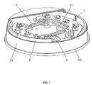
- Fig. 1 is a drum brake of the present invention having the interconnected multi-degrees-of-freedom shoes and automatic adjusting mechanism of brake clearance.
- Fig. 2 is the brake assembly, without drum, of the present invention in Fig. 1.
- Fig. 3(a) shows subassembly of a composite shoe in Fig. 1.
- Fig. 3(b) is the exploded view of the composite shoe in Fig. 3(a).
- Fig. 4(a) shows subassembly of the other composite shoe in Fig. 1.
- Fig. 4(b) is the exploded view of the composite shoe in Fig. 4(a).
- Fig. 5(a) shows subassembly of the interconnected shoe mechanism I in Fig. 1.
- Fig. 5(b) is the exploded view of the interconnected shoe mechanism in Fig. 5(a).
- Fig. 6(a) shows assembly of the interconnected shoe mechanism, the automatic clearance adjusting mechanism and the backplate in Fig. 1.
- Fig. 6(b) is the exploded view of the assembly of the interconnected shoe mechanism, the automatic clearance adjusting mechanism and the backplate in Fig. 6(a).
- a type of drum brake of the present invention having the interconnected shoe mechanism of two degrees of freedom according to an embodiment of the invention will be described hereunder with reference to Fig. 1 and Fig. 2.
- This type of drum brake consists of two sets of interconnected shoe mechanisms I , two sets of automatic clearance adjusting mechanisms II, backplate III, drum IV and two pull-off springs V.
- a parking brake mechanism can also be exerted in the assembly when necessary.
- One interconnected shoe mechanism I is pivoted on one side of backplate III by cylindrical anchor pins 14 and 24.
- One automatic clearance adjusting mechanism is fitted on the same side.
- a friction plate 31 is fixed on backplate III by shaft 33, and pin 32 is fixed on friction plate 31, the tip of which is housed in slot 114 in limb 11b of outer driving lever 11, as shown in Fig. 6.
- the other interconnected shoe mechanism and its automatic clearance adjusting mechanism are fitted on the other side of backplate III in the same way as above. Because the two sets of interconnected shoe mechanism and automatic clearance adjusting mechanism are completely same, only
- a composite shoe consists of shoe 12 and driving lever 11.
- the shoe 12 is jointed to driving lever 11 with cylindrical pin 13 and can rotate about pin 13, and the driving lever 11 is pivoted on backplate III with cylindrical anchor pin 14.
- the other composite shoe in Fig. 4(a) and (b) consists of shoe 22 and driving lever 21.
- the shoe 22 is jointed to driving lever 21 with cylindrical pin 23 and can rotate about pin 23, and the driving lever 21 is pivoted on backplate III with cylindrical anchor pin 24.
- the two composite shoes constitute the interconnected shoe mechanism I , and the shoes 12 and 22 are interconnected with a slide joint mechanism consisting of slide block 4 and cylindrical pin 3, as seen in Fig. 5(a) and (b).
- the driving levers 11 and 21 are also interconnected with a slide joint mechanism consisting of cylindrical pin 5 and slide blocks 6, and the pin 5 passes through holes 113 in driving lever 11 and the holes in slide blocks 6.
- the slide blocks 6 can slide in oblong holes 213 in driving lever 21, and the two driving levers have the same radial displacement at the joint and do not interfere in the circumferential direction. So the interconnected shoe mechanism has two degrees of freedom. If the slide joint between driving levers 11 and 21 is cancelled, the interconnected shoe mechanism would have three degrees of freedom.
- the interconnected shoe mechanism would have three degrees of freedom, including a degree of freedom of roll about axis connecting the two spherical anchor joints; if the slide joint between driving levers 11 and 21 is cancelled, the interconnected shoe mechanism would have four degrees of freedom.
- the interconnected shoe mechanism would have three degrees of freedom, including a degree of freedom of roll about axis connecting the two elliptical anchor joints; if the slide joint between driving levers 11 and 21 is cancelled, the interconnected shoe mechanism would have four degrees of freedom.
- Each driving lever of the interconnected shoe mechanism has two limbs to house other parts inbetween them.
- driving lever 11 has two limbs, 11a and 11b, the rivet 119 rivets limbs 11a and 11b through holes 118.
- driving lever 21 has also two limbs, 21a and 21b, the rivet 219 rivets limbs 21a and 21b through holes 218.
- the driving lever 21 is housed inbetween limb 11a and 11b, and the webs of shoes 12 and 22 are housed inbetween limb 21a and 21b.
- the driving levers 11 and 21 are arranged in the opposite direction to each other, and there is a certain distance between anchor pins 14 and 24; the tip 110 of driving lever 11 and the anchor pin 24 of driving lever 21 are in one side, and the tip 210 of driving lever 21 and the anchor pin 14 of driving lever 11 are in the other side.
- There are several holes in each driving lever as seen in Fig. 3 (a) and (b), hole 111 mating with anchor pin 14, hole 112 mating with shoe joint pin 13, and hole 113 mating with cylindrical pin 3 (as also seen in Fig. 5 (a) and (b)).
- Fig. 3 (a) and (b) There are holes 115 and 116 in driving lever 11 for shoe joint pin 23 and anchor pin 24 not to interfere with driving lever 11 when the latter rotates about anchor pin 14.
- hole 211 mates with anchor pin 24, hole 212 mates with shoe joint pin 23, and oblong holes 213 mate with the slide blocks 6 (as seen in Fig. 5 (a) and (b)).
- holes 215 and 216 in driving lever 21 for shoe joint pin 13 and anchor pin 14 not to interfere with driving lever 21 when the latter rotates about anchor pin 24.
- the automatic clearance adjusting mechanism consists of friction plate 31, pin 32, shaft 33 and spring 34, etc..
- the friction plate 31 is fitted on backplate III with shaft 33.
- the pin 32 is fixed on the friction plate 31, and its tip is housed in slot 114 in limb 11b of outer driving lever 11.
- the spring 34 is used to develop the friction force between friction plate 31 and backplate III.
- the gap between pin 32 and a long side of slot 114 allows the driving levers free to take the shoes back from drum IV, and the long side of slot 114 is held hard against pin 32 by means of the pull-off springs V connecting the driving levers, without rotation of friction plate 31 relative to backplate III.
- friction plate 31 shall be overcoming the friction force between friction plate 31 and backplate III and rotating about shaft 33 to maintain the required clearance between drum and linings, if lining wear occurs.
Landscapes
- Engineering & Computer Science (AREA)
- General Engineering & Computer Science (AREA)
- Mechanical Engineering (AREA)
- Braking Arrangements (AREA)
Applications Claiming Priority (3)
| Application Number | Priority Date | Filing Date | Title |
|---|---|---|---|
| CN00124983A CN1284615A (zh) | 2000-09-29 | 2000-09-29 | 具有多自由度联动蹄的蹄-鼓式制动器 |
| CN00124983 | 2000-09-29 | ||
| PCT/CN2001/001461 WO2002036980A1 (fr) | 2000-09-29 | 2001-09-28 | Frein a tambour presentant une garniture a multiples degres de liberte |
Publications (2)
| Publication Number | Publication Date |
|---|---|
| EP1321690A1 true EP1321690A1 (de) | 2003-06-25 |
| EP1321690A4 EP1321690A4 (de) | 2006-05-03 |
Family
ID=4590786
Family Applications (1)
| Application Number | Title | Priority Date | Filing Date |
|---|---|---|---|
| EP01992842A Withdrawn EP1321690A4 (de) | 2000-09-29 | 2001-09-28 | Trommelbremse mit bremsschuh mit mehreren freiheitsgraden |
Country Status (8)
| Country | Link |
|---|---|
| EP (1) | EP1321690A4 (de) |
| JP (1) | JP4001816B2 (de) |
| KR (1) | KR100552392B1 (de) |
| CN (2) | CN1284615A (de) |
| AU (1) | AU2002223413A1 (de) |
| BR (1) | BR0107278A (de) |
| RU (1) | RU2279578C2 (de) |
| WO (1) | WO2002036980A1 (de) |
Cited By (1)
| Publication number | Priority date | Publication date | Assignee | Title |
|---|---|---|---|---|
| US7077249B2 (en) * | 2000-09-29 | 2006-07-18 | Tsinghua University | Drum brakes with interconnected multi-degrees-of-freedom shoes |
Families Citing this family (8)
| Publication number | Priority date | Publication date | Assignee | Title |
|---|---|---|---|---|
| KR200451823Y1 (ko) * | 2009-05-09 | 2011-01-13 | 박정주 | 거품기 |
| RU2439390C2 (ru) * | 2009-06-22 | 2012-01-10 | Открытое акционерное общество "Автомобильный завод "Урал" | Колодочный тормоз |
| DE102009029090A1 (de) * | 2009-09-02 | 2011-03-31 | Robert Bosch Gmbh | Notbremssystem für Werkzeugmaschinen |
| CN105020300A (zh) * | 2015-06-18 | 2015-11-04 | 盐城市诚良高尔夫电动车配件有限公司 | 一种毂式制动器 |
| CN107339341A (zh) * | 2016-05-03 | 2017-11-10 | 任天伟 | 鼓式制动器总成平衡优化方法及使用该方法的鼓式制动器 |
| CN108506373A (zh) * | 2018-03-13 | 2018-09-07 | 浙江零跑科技有限公司 | 一种集成型轮毂电机式制动器 |
| US11015664B1 (en) * | 2021-01-25 | 2021-05-25 | Kan Cui | Rotation-actuated drum brake |
| US20240123962A1 (en) * | 2022-10-13 | 2024-04-18 | ZF Active Safety US Inc. | Apparatus for drum brake assembly |
Family Cites Families (7)
| Publication number | Priority date | Publication date | Assignee | Title |
|---|---|---|---|---|
| GB671120A (en) * | 1949-04-27 | 1952-04-30 | Heinrich Hense | Improvements in or relating to internal expanding brakes |
| US3894620A (en) * | 1974-03-26 | 1975-07-15 | David N Goldberg | Articulated friction unit assembly for brake or clutch use |
| DE2744442A1 (de) * | 1977-10-03 | 1979-04-12 | Kloeckner Humboldt Deutz Ag | Trommelbremse, insbesondere fuer land- und/oder bauwirtschaftlich nutzbare kraftfahrzeuge mit einer doppelbremstrommel |
| GB2015098B (en) * | 1978-02-22 | 1982-04-28 | Girling Ltd | Drum brakes for vehicles |
| DE8514496U1 (de) * | 1985-05-15 | 1986-09-11 | Lucas Industries P.L.C., Birmingham, West Midlands | Trommelbremse mit drei Bremsbacken |
| JP3974963B2 (ja) * | 1996-11-19 | 2007-09-12 | 本田技研工業株式会社 | 車両用ドラムブレーキ |
| JPH1182567A (ja) * | 1997-09-03 | 1999-03-26 | Akebono Brake Ind Co Ltd | デュオサーボ式ドラムブレーキ |
-
2000
- 2000-09-29 CN CN00124983A patent/CN1284615A/zh active Pending
-
2001
- 2001-09-28 EP EP01992842A patent/EP1321690A4/de not_active Withdrawn
- 2001-09-28 BR BR0107278-1A patent/BR0107278A/pt not_active Application Discontinuation
- 2001-09-28 WO PCT/CN2001/001461 patent/WO2002036980A1/zh not_active Ceased
- 2001-09-28 JP JP2002539702A patent/JP4001816B2/ja not_active Expired - Fee Related
- 2001-09-28 KR KR1020027006646A patent/KR100552392B1/ko not_active Expired - Fee Related
- 2001-09-28 RU RU2002113911/11A patent/RU2279578C2/ru active
- 2001-09-28 AU AU2002223413A patent/AU2002223413A1/en not_active Abandoned
- 2001-09-28 CN CN01802603A patent/CN1388873A/zh active Pending
Cited By (1)
| Publication number | Priority date | Publication date | Assignee | Title |
|---|---|---|---|---|
| US7077249B2 (en) * | 2000-09-29 | 2006-07-18 | Tsinghua University | Drum brakes with interconnected multi-degrees-of-freedom shoes |
Also Published As
| Publication number | Publication date |
|---|---|
| AU2002223413A1 (en) | 2002-05-15 |
| JP4001816B2 (ja) | 2007-10-31 |
| RU2279578C2 (ru) | 2006-07-10 |
| CN1284615A (zh) | 2001-02-21 |
| BR0107278A (pt) | 2002-08-13 |
| EP1321690A4 (de) | 2006-05-03 |
| RU2002113911A (ru) | 2004-02-27 |
| CN1388873A (zh) | 2003-01-01 |
| KR100552392B1 (ko) | 2006-02-20 |
| KR20020068047A (ko) | 2002-08-24 |
| WO2002036980A1 (fr) | 2002-05-10 |
| JP2004512485A (ja) | 2004-04-22 |
Similar Documents
| Publication | Publication Date | Title |
|---|---|---|
| JP7710983B2 (ja) | ブレーキキャリパ用のパッド・スプリングアセンブリ | |
| KR920006626B1 (ko) | 이중 디스크 브레이크 | |
| US5860496A (en) | Pin guided push-pull caliper | |
| EP1105658B1 (de) | Mehrscheibenbremseinrichtung mit integrierter feststellbremse | |
| US7316301B2 (en) | Brake caliper | |
| JPH0366538B2 (de) | ||
| EP1321690A1 (de) | Trommelbremse mit bremsschuh mit mehreren freiheitsgraden | |
| JPS6054533B2 (ja) | フロ−テイングキヤリパ型デイスクブレ−キ | |
| EP1234124B1 (de) | Teilbelag-scheibenbremse mit feststellbremse | |
| US3059731A (en) | Disk brakes | |
| US7077249B2 (en) | Drum brakes with interconnected multi-degrees-of-freedom shoes | |
| JPH10508680A (ja) | ドラムブレーキ用機械的駆動装置 | |
| US3703944A (en) | Disk parking and service brake having servo action on parking brake only | |
| EP0816706A2 (de) | Bimodale Trommelbremse mit einem Feststellbremshebel, der um eine zur Bremsträgerplatte senkrecht stehende Achse dreht | |
| US3708040A (en) | Disk brake with servo action | |
| ITMI980062A1 (it) | Dispositivo di posizionamento assiale della fascia frenante per freni a disco | |
| US4374554A (en) | Duo-servo drum brake | |
| US3331473A (en) | Disc brake with self-energized brake shoe | |
| US11982329B2 (en) | Caliper bridge for a disc brake with means for controlling rotation of threaded wear adjustment tubes | |
| US2906375A (en) | Brake assembly | |
| CN119604691A (zh) | 用于车辆的制动组件和用于施加驻车制动力的方法 | |
| JPS6323035A (ja) | ブレ−キアクチユエ−タ | |
| US6554110B2 (en) | Drum brake device | |
| US4768624A (en) | Self-energizing disc brakes with cable assembly and cable casing therefor | |
| CA1277606C (en) | Brake assembly and rotary cam member therefor |
Legal Events
| Date | Code | Title | Description |
|---|---|---|---|
| PUAI | Public reference made under article 153(3) epc to a published international application that has entered the european phase |
Free format text: ORIGINAL CODE: 0009012 |
|
| 17P | Request for examination filed |
Effective date: 20021018 |
|
| AK | Designated contracting states |
Designated state(s): AT BE CH CY DE DK ES FI FR GB GR IE IT LI LU MC NL PT SE TR |
|
| AX | Request for extension of the european patent |
Extension state: AL LT LV MK RO SI |
|
| A4 | Supplementary search report drawn up and despatched |
Effective date: 20060317 |
|
| RIC1 | Information provided on ipc code assigned before grant |
Ipc: F16D 51/32 20060101AFI20060313BHEP |
|
| 17Q | First examination report despatched |
Effective date: 20061108 |
|
| GRAP | Despatch of communication of intention to grant a patent |
Free format text: ORIGINAL CODE: EPIDOSNIGR1 |
|
| STAA | Information on the status of an ep patent application or granted ep patent |
Free format text: STATUS: THE APPLICATION IS DEEMED TO BE WITHDRAWN |
|
| 18D | Application deemed to be withdrawn |
Effective date: 20080411 |