EP1323699A1 - Procédé pour la préparation d'éther diméthylique - Google Patents
Procédé pour la préparation d'éther diméthylique Download PDFInfo
- Publication number
- EP1323699A1 EP1323699A1 EP02028785A EP02028785A EP1323699A1 EP 1323699 A1 EP1323699 A1 EP 1323699A1 EP 02028785 A EP02028785 A EP 02028785A EP 02028785 A EP02028785 A EP 02028785A EP 1323699 A1 EP1323699 A1 EP 1323699A1
- Authority
- EP
- European Patent Office
- Prior art keywords
- dimethyl ether
- methanol
- district
- distillation column
- manufacturing
- Prior art date
- Legal status (The legal status is an assumption and is not a legal conclusion. Google has not performed a legal analysis and makes no representation as to the accuracy of the status listed.)
- Withdrawn
Links
Images


Classifications
-
- C—CHEMISTRY; METALLURGY
- C07—ORGANIC CHEMISTRY
- C07C—ACYCLIC OR CARBOCYCLIC COMPOUNDS
- C07C41/00—Preparation of ethers; Preparation of compounds having groups, groups or groups
- C07C41/01—Preparation of ethers
- C07C41/09—Preparation of ethers by dehydration of compounds containing hydroxy groups
Definitions
- the present invention relates to a method of manufacturing dimethyl ether (DME).
- DME dimethyl ether
- LPG Liquefied petroleum gas
- the price of LPG if delivered to the consuming district, e.g., household, is more than 10 times as high as the import price. Therefore, dimethyl ether attracts attention as a substitute for LPG in recent years, thus utilization studies are now being carried out.
- dimethyl ether in the producing district of a natural gas by using as the raw material a natural gas or methanol synthesized from the natural gas.
- the manufactured dimethyl ether is liquefied under a high pressure and the liquefied dimethyl ether is loaded in a high pressure tank or cylinder for transport to the consuming district.
- the manufactured dimethyl ether is cooled to temperatures lower than -25°C and packed in a freezing tank under atmospheric pressure for transport to the consuming district.
- dimethyl ether gives rise to the problems transportation and storage costs. Also, where dimethyl ether is stored in a high pressure tank, it is necessary to supervise the safety of the high pressure gas in the dimethyl ether producing district.
- the present invention is intended to provide a method of manufacturing dimethyl ether and supplying it to the consuming district at a low total cost.
- a liquid methanol that can be handled easily is transported under room temperature and atmospheric pressure from the methanol producing district to the dimethyl ether consuming district, and dimethyl ether is manufactured in the district where it is consumed, which markedly lowers the transport and storage costs, thereby lowering the total cost.
- the present invention is also intended to provide a method of manufacturing dimethyl ether, which permits converting the raw material containing methanol into dimethyl ether and also permits converting methanol contained in water separated and discharged from a distillation column into hydrogen and carbon dioxide by utilizing the heat generated in converting the methanol-containing raw material into dimethyl ether so as to effectively utilize the methanol.
- a method of manufacturing dimethyl ether comprising transporting a raw material containing methanol under room temperature and under atmospheric pressure to the dimethyl ether consuming district or its neighboring district, and converting the methanol into dimethyl ether.
- methanol is produced in the producing district of a natural gas, such as the Middle or Near East, and transported to the dimethyl ether (DME) consuming district or neighboring district, under room temperature and atmospheric pressure.
- DME dimethyl ether
- the consuming district of DME or its neighboring district includes, for example, 1) the district in which is erected a city gas manufacturing plant utilizing DME as a substitute for an LPG for the heat control of the city gas, 2) the site in which is operated a taxi service utilizing DME in place of an LPG as a fuel of a diesel engine vehicle, 3) the site in which is sold DME housed in cylinders as a substitute for LPG, and 4) a household in which DME is utilized as a fuel.
- methanol having a purity of, for example, 100% is used as a raw material, and the reaction is carried out in the presence of a catalyst for synthesizing DME, such as an alumina series catalyst, under temperatures of 240°C to 320°C and under an atmospheric pressure.
- a catalyst for synthesizing DME such as an alumina series catalyst
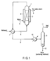
- DME can be manufactured in a manufacturing plant, as shown in FIGS. 1 and 2.
- the manufacturing plant shown in FIG. 1 comprises a reaction tower 1.
- a catalyst loading section 2 is arranged within the reaction tower 1, and a cooling chamber 3 in which is circulated a cooling fluid, e.g., water, is arranged to surround the outer surface of the reaction tower 1.
- a water supply passageway 4 is connected to a region in the vicinity of the bottom portion of the cooling chamber 3.
- a steam discharge passageway 5 is connected to an upper portion of the cooling chamber 3.
- a raw material supply passageway 6 is connected to the bottom portion of the reaction tower 1. Also, a heat exchanger 7 is mounted to the raw material supply passageway 6.
- a DME distillation column 8 is connected to the reaction tower 1 via a fluid passageway 9 connected to the upper portion of the reaction tower 1.
- the fluid passageway 9 extends to cross the heat exchanger 7. Further, a cooling device 10 is mounted to the fluid passageway 9.
- methanol having a purity of, for example, 100%, which is heated to 240 to 320°C, is supplied into the reaction tower 1 through the raw material supply passageway 6, and DME is synthesized in the presence of a catalyst for synthesizing DME loaded in the loading section 2.
- the synthesizing reaction of DME is an exothermic reaction and, thus, it is possible to obtain a hot water or steam from the steam discharge passageway 5 by supplying water into the cooling chamber 3 through the water supply passageway 4.
- the reaction mixture containing DME is supplied into the DME distillation column 8 through the fluid passageway 9.
- a heat exchange is performed in the heat exchanger 7 between the reaction mixture and the raw material circulated through the raw material supply passageway 6, with the result that the reaction mixture is cooled and the raw material is heated. Further, the reaction mixture is cooled in the cooling device 10 and, then, supplied into the DME distillation column 8.
- the reaction mixture supplied into the DME distillation column 8 is separated into DME and water containing methanol.
- the separated DME is discharged from the top of the distillation column 8 through a fluid passageway 11.
- the separated water containing methanol is discharged from the bottom portion of the distillation column 8 through a fluid passageway 12.
- two loading members (or trays) 14a and 14b are arranged separately from each other in the vertical direction inside the methanol distillation column 13.
- a circulation passageway 15 is connected at one end to the bottom portion of the methanol distillation column 13 and at the other end to that portion of the methanol distillation column 13 which is positioned below the lower loading member 14b.
- a pump 16 and a heat exchanger 17 are mounted to the circulation passageway 15 in the order mentioned as viewed from the side of the bottom portion of the methanol distillation column 13.
- a branched passageway 20 is branched from the circulation passageway 15, and a valve 18 and a cooling device 19 are mounted to the branched passageway 20.
- the top portion of the methanol distillation column 13 is joined to a gas-liquid separator 21 via a fluid passageway 22, and a cooling device 23 is mounted to the fluid passageway 22.
- the gas-liquid separator 21 is joined to the upper side wall of the methanol distillation column 13 via a returning fluid passageway 24. Further, a fluid passageway 25 for discharging methanol and DME is connected to the gas-liquid separator 21.
- the fluid passageway 11 for discharging DME which is shown in FIG. 1, is connected to that portion of the methanol distillation column 13 which is positioned below the lower loading member 14b.
- the fluid passageway 12 for discharging water containing methanol which is shown in FIG. 1, is connected to that portion of the methanol distillation column 13 which is positioned between the upper and lower loading members 14a and 14b.
- DME and water containing methanol are supplied through the fluid passageways 11 and 12, respectively, into the methanol distillation column 13, with the valve 18 that is mounted to the branched passageway 20 closed.
- the pump 18 is driven and, for example, steam is supplied into the heat exchanger 17 so as to heat the bottom portion of the distillation column 13.
- the DME supplied through the fluid passageway 11 is heated in the bottom portion of the methanol distillation column 13 so as to be moved upward within the distillation column 13.
- the methanol containing water, which is supplied through the fluid passageway 12 is stripped in the lower loading member 14b and the upper loading member 14a.
- methanol is distilled and, at the same time, the water containing undistilled methanol is stored in the bottom portion of the distillation column 13.
- the water containing the undistilled methanol, which is stored in the bottom portion of the distillation column 13, is circulated through the circulation passageway 15 by the driving of the pump 16. During the circulation, the water containing the undistilled methanol is heated in the heat exchanger 17 so as to distill methanol in the bottom portion of the distillation column 13.
- Methanol containing steam and DME are circulated through the fluid passageway 22 connected to the top portion of the distillation column 13. During the circulation, methanol containing steam and DME are cooled by the cooling device 23 and, then, supplied into the gas-liquid separator 21. In the gas-liquid separator 21, methanol containing steam and DME are separated into methanol, DME and water. The separated methanol and DME are discharged and recovered through the fluid passageway 25, and the separated water is returned to the distillation column 13 through the returning fluid passageway 24.
- the heated water stored in the bottom portion of the distillation column 13, the methanol content of said heated water being substantially zero, is discharged to the outside through the branched passageway 20 by opening the valve 18 and, then, cooled in the cooling device 19 mounted to the branched passageway 20.
- methanol is transported under room temperature and atmospheric pressure from the dimethyl ether producing district to the consuming district, or its neighboring district, and the transported methanol is converted into DME in the consuming district.
- the particular method of the present invention is markedly advantageous in terms of transportation cost, over the conventional method in which DME is manufactured in the methanol producing district, then the manufactured DME is liquefied under a high pressure and the liquefied DME is housed in a high pressure tank or cylinder for transportation to the DME consuming district, or the manufactured DME is cooled to temperatures not higher than -25°C and housed in a refrigeration tank under atmospheric pressure for transportation to the consuming district.
- the present invention produces prominent effects as summarized below:
- FIG. 3 schematically shows the construction of a dimethyl ether manufacturing plant used in the second embodiment of the present invention.
- the dimethyl ether manufacturing plant includes a cylindrical internal reactor 31.
- a DME synthesizing catalyst such as an alumina series catalyst
- a raw material supply passageway 35 is connected to the bottom portion of the internal reactor 31.
- First and second heat exchangers 36, 37 are mounted to the raw material supply passageway 35.
- a DME distillation column 38 is connected to the internal reactor 31 through a fluid passageway 39 1 connected to the upper portion of the internal reactor 31.
- the fluid passageway 39 1 extends to cross the first heat exchanger 36.
- a cooling device 40 is mounted to the fluid passageway 39 1 .
- the bottom portion of the distillation column 38 is connected to the external reactor 34 through a fluid passageway 39 2 .
- a pump 41 is mounted to the fluid passageway 39 2 in the vicinity of the distillation column 38. Also, the fluid passageway 39 2 extends to cross the second heat exchanger 37.
- a branched raw material supply passageway 42 is branched from the raw material supply passageway 35 so as to be connected to the fluid passageway 39 2 . Further, a discharge passageway 44 having a cooling device 43 mounted thereto is connected to the external reactor 34.
- the raw material heated to 240 to 320°C e.g., methanol having a purity of 100%
- methanol having a purity of 100%
- DME is synthesized in the presence of a DME synthesizing catalyst such as an alumina-based catalyst in the loading section 32.
- the reaction to synthesize DME is an exothermic reaction.
- the reaction mixture containing DME is supplied into the DME distillation column 38 through the fluid passageway 39 1 . While passing through the fluid passageway 39 1 , the reaction mixture exchanges heat within the first heat exchanger 36 with the raw material passing through the raw material supply passageway 35, with the result that the reaction mixture is cooled, and the raw material is heated. The reaction mixture is further cooled in the cooling device 40 and, then, supplied into the distillation column 38. The reaction mixture supplied into the distillation column 38 is separated into DME and water containing methanol. The separated DME is discharged from the top portion of the distillation column 38 so as to be recovered.
- the water containing methanol is supplied by the driving of the pump 41 from the bottom portion of the distillation column 38 into the annular external reactor 34 through the fluid passageway 39 2 . While passing through the fluid passageway 39 2 , the water containing methanol exchanges heat within the second heat exchanger 37 with the raw material passing through the raw material supply passageway 35, with the result that the water is heated and the raw material is cooled.
- the methanol contained in the water supplied into the external reactor 34 is reformed in the presence of the methanol reforming catalyst in the loading section 33 so as to generate hydrogen and carbon dioxide.
- the methanol reforming reaction is an endothermic reaction
- the DME synthesizing reaction is an exothermic reaction. It follows that it is possible to maintain a good heat balance during the reactions so as to effectively utilize the heat.
- the raw material methanol is introduced from the raw material supply passageway 35 into the fluid passageway 39 2 , through which flows water containing methanol, via the branched raw material supply passageway 42.
- the hydrogen and carbon dioxide formed in the external reactor 34 are discharged and recovered through the discharge passageway 44 having the cooling device mounted thereto.
- the raw material containing methanol can be converted into DME, and the methanol contained in the water separated in and discharged from the distillation column can be effectively utilized.
- methanol heated to 240°C to 320°C is supplied into a reaction tower, and DME is synthesized in the presence of a DME synthesizing catalyst such as an alumina-based catalyst in the loading section.
- a DME synthesizing catalyst such as an alumina-based catalyst in the loading section.
- the reaction to synthesize DME is an exothermic reaction.
- the reaction mixture containing DME is cooled and, then, supplied into the DME distillation column so as to be separated into DME and water containing methanol.
- the separated DME is discharged from the top portion of the distillation column so as to be recovered, and the water containing methanol is discharged from the bottom portion of the distillation column.
- the water discharged from the bottom portion of the DME distillation column certainly contains methanol.
- methanol contained in the discharged water is not effectively utilized but is discarded.
- the raw material containing methanol can be converted into DME within the internal reactor 31.
- the methanol-containing water separated from the DME distillation column 38 is supplied into the annular external reactor 34 surrounding the internal reactor 31 so as to decompose methanol by utilizing the heat generated within the internal reactor 31 (exothermic reaction) and the methanol decomposing catalyst loaded in the external reactor 34, thereby obtaining mainly hydrogen. It follows that the raw material containing methanol can be converted into DME, and the methanol contained in the water separated in and discharged from the distillation column 38 can be effectively utilized.
- the raw material methanol used in the methanol decomposing reaction can be introduced from the raw material supply passageway 35 into the fluid passageway 39 2 , through which flows the methanol-containing water, via the branched raw material supply passageway 42. It follows that, even where the amount of methanol in the bottom portion of the distillation column 38 is small, it is possible to decompose methanol effectively so as to obtain hydrogen with a high stability.
- the reactor loaded with a DME synthesizing catalyst is arranged inside, and the reactor loaded with a methanol decomposing catalyst is arranged outside.
- the reactor loaded with a methanol decomposing catalyst is arranged outside.
- the method of the present invention for manufacturing dimethyl ether makes it possible to transport methanol, which is liquid under room temperature and atmospheric pressure and, thus, can be handled easily, from the methanol producing district to the consuming district of dimethyl ether for manufacturing dimethyl ether in the consuming district. It follows that the transporting cost and the storing cost can be markedly lowered so as to make it possible to supply dimethyl ether of a low cost to, for example, the owner of a city gas manufacturing plant, the taxi service operator, the seller of dimethyl ether as a substitute for an LPG, and the household.
- the present invention also provides a method of manufacturing dimethyl ether, which makes it possible to convert the raw material containing methanol into dimethyl ether and to convert the methanol contained in the water separated in and discharged from the distillation column into hydrogen by utilizing the heat generated from the reaction to synthesize dimethyl ether.
Landscapes
- Chemical & Material Sciences (AREA)
- Organic Chemistry (AREA)
- Organic Low-Molecular-Weight Compounds And Preparation Thereof (AREA)
Applications Claiming Priority (4)
| Application Number | Priority Date | Filing Date | Title |
|---|---|---|---|
| JP2001401509 | 2001-12-28 | ||
| JP2001401509A JP4088442B2 (ja) | 2001-12-28 | 2001-12-28 | ジメチルエーテルの製造方法 |
| JP2002024527A JP4043248B2 (ja) | 2002-01-31 | 2002-01-31 | ジメチルエーテルの製造方法 |
| JP2002024527 | 2002-01-31 |
Publications (1)
| Publication Number | Publication Date |
|---|---|
| EP1323699A1 true EP1323699A1 (fr) | 2003-07-02 |
Family
ID=26625411
Family Applications (1)
| Application Number | Title | Priority Date | Filing Date |
|---|---|---|---|
| EP02028785A Withdrawn EP1323699A1 (fr) | 2001-12-28 | 2002-12-23 | Procédé pour la préparation d'éther diméthylique |
Country Status (3)
| Country | Link |
|---|---|
| US (1) | US6924399B2 (fr) |
| EP (1) | EP1323699A1 (fr) |
| CN (1) | CN1429802A (fr) |
Cited By (2)
| Publication number | Priority date | Publication date | Assignee | Title |
|---|---|---|---|---|
| US20120247002A1 (en) * | 2011-04-01 | 2012-10-04 | Christophe Duwig | process for preparing a fuel for automotive applications, stationary engines and marine applications by catalytic liquid phase alcohol conversion and a compact device for carrying out the process |
| CN113559792A (zh) * | 2021-07-15 | 2021-10-29 | 成都众奇化工有限公司 | 一种二甲醚合成反应器及二甲醚合成工艺 |
Families Citing this family (8)
| Publication number | Priority date | Publication date | Assignee | Title |
|---|---|---|---|---|
| FI20085400A0 (fi) * | 2007-11-09 | 2008-04-30 | Upm Kymmene Oyj | Menetelmä jäteveden integroidulle käsittelylle |
| ATE514669T1 (de) * | 2007-08-23 | 2011-07-15 | Haldor Topsoe As | Verfahren zur herstellung von dimethylether |
| US8293805B2 (en) * | 2008-05-29 | 2012-10-23 | Schlumberger Technology Corporation | Tracking feedstock production with micro scale gas-to-liquid units |
| US20100000153A1 (en) * | 2008-07-07 | 2010-01-07 | Kyrogen Usa, Llc | Remote micro-scale gtl products for uses in oil- and gas-field and pipeline applications |
| DE102008058931B4 (de) * | 2008-11-25 | 2010-12-30 | Lurgi Gmbh | Verfahren und Vorrichtung zum Herstellen von Dimethylether aus Methanol |
| WO2011095270A1 (fr) * | 2010-02-04 | 2011-08-11 | Haldor Topsøe A/S | Procédé de préparation d'éther diméthylique |
| JP5812781B2 (ja) * | 2011-09-21 | 2015-11-17 | 三菱重工業株式会社 | メタノールからガソリンと水素を製造する方法および装置 |
| CN111075620B (zh) * | 2019-12-19 | 2021-08-13 | 浙江吉利新能源商用车集团有限公司 | 一种增程器冷启动系统及汽车 |
Citations (7)
| Publication number | Priority date | Publication date | Assignee | Title |
|---|---|---|---|---|
| US4560807A (en) * | 1983-04-27 | 1985-12-24 | Mitsubishi Chemical Industries, Ltd. | Process for the production of dimethyl ether useful as a propellant |
| EP0270852A2 (fr) * | 1986-11-18 | 1988-06-15 | RWE-DEA Aktiengesellschaft für Mineraloel und Chemie | Procédé pour la préparation de diméthyl-éther pur |
| EP0285004A1 (fr) * | 1987-03-30 | 1988-10-05 | RWE-DEA Aktiengesellschaft für Mineraloel und Chemie | Procédé pour la préparation de l'éther diméthylique |
| US4885405A (en) * | 1987-12-10 | 1989-12-05 | Horst Dornhagen | Process for the production of pure dimethylether and a catalyst used in the process |
| US5316627A (en) * | 1991-10-04 | 1994-05-31 | Rwe-Dea Aktiengesellschaft Fuer Mineraloel Und Chemie | Process for producing odorless dimethyl ether |
| US5750799A (en) * | 1995-03-15 | 1998-05-12 | Starchem, Inc. | Dimethyl ether production and recovery from methanol |
| DE19943219A1 (de) * | 1999-09-09 | 2001-03-15 | Axiva Gmbh | Verfahren zur Herstellung von Dimethylether |
Family Cites Families (5)
| Publication number | Priority date | Publication date | Assignee | Title |
|---|---|---|---|---|
| US4341069A (en) * | 1980-04-02 | 1982-07-27 | Mobil Oil Corporation | Method for generating power upon demand |
| JPS59152205A (ja) * | 1983-02-14 | 1984-08-30 | Mitsubishi Gas Chem Co Inc | メタノ−ルの水蒸気改質法 |
| DE3340569A1 (de) * | 1983-11-09 | 1985-05-23 | Sued Chemie Ag | Katalysator zur herstellung von synthesegas bzw. von wasserstoff und verfahren zu dessen herstellung |
| JPH086970B2 (ja) * | 1992-03-31 | 1996-01-29 | 工業技術院長 | メタノールの分解、合成反応を利用した広域熱輸送、熱利用、熱回収方法及び装置 |
| US5498370A (en) * | 1994-12-15 | 1996-03-12 | Amoco Corporation | Process for hydroshifting dimethyl ether |
-
2002
- 2002-12-11 US US10/316,086 patent/US6924399B2/en not_active Expired - Fee Related
- 2002-12-23 EP EP02028785A patent/EP1323699A1/fr not_active Withdrawn
- 2002-12-27 CN CN02160838A patent/CN1429802A/zh active Pending
Patent Citations (7)
| Publication number | Priority date | Publication date | Assignee | Title |
|---|---|---|---|---|
| US4560807A (en) * | 1983-04-27 | 1985-12-24 | Mitsubishi Chemical Industries, Ltd. | Process for the production of dimethyl ether useful as a propellant |
| EP0270852A2 (fr) * | 1986-11-18 | 1988-06-15 | RWE-DEA Aktiengesellschaft für Mineraloel und Chemie | Procédé pour la préparation de diméthyl-éther pur |
| EP0285004A1 (fr) * | 1987-03-30 | 1988-10-05 | RWE-DEA Aktiengesellschaft für Mineraloel und Chemie | Procédé pour la préparation de l'éther diméthylique |
| US4885405A (en) * | 1987-12-10 | 1989-12-05 | Horst Dornhagen | Process for the production of pure dimethylether and a catalyst used in the process |
| US5316627A (en) * | 1991-10-04 | 1994-05-31 | Rwe-Dea Aktiengesellschaft Fuer Mineraloel Und Chemie | Process for producing odorless dimethyl ether |
| US5750799A (en) * | 1995-03-15 | 1998-05-12 | Starchem, Inc. | Dimethyl ether production and recovery from methanol |
| DE19943219A1 (de) * | 1999-09-09 | 2001-03-15 | Axiva Gmbh | Verfahren zur Herstellung von Dimethylether |
Cited By (2)
| Publication number | Priority date | Publication date | Assignee | Title |
|---|---|---|---|---|
| US20120247002A1 (en) * | 2011-04-01 | 2012-10-04 | Christophe Duwig | process for preparing a fuel for automotive applications, stationary engines and marine applications by catalytic liquid phase alcohol conversion and a compact device for carrying out the process |
| CN113559792A (zh) * | 2021-07-15 | 2021-10-29 | 成都众奇化工有限公司 | 一种二甲醚合成反应器及二甲醚合成工艺 |
Also Published As
| Publication number | Publication date |
|---|---|
| US6924399B2 (en) | 2005-08-02 |
| US20030121200A1 (en) | 2003-07-03 |
| CN1429802A (zh) | 2003-07-16 |
Similar Documents
| Publication | Publication Date | Title |
|---|---|---|
| US12030838B2 (en) | Method and system for the production of methanol | |
| CA2292178C (fr) | Methode de production de methanol | |
| US6894080B2 (en) | Method of manufacturing methanol | |
| US6753352B2 (en) | Method for manufacturing synthesis gas and method for manufacturing methanol | |
| US4865624A (en) | Method for steam reforming methanol and a system therefor | |
| CA2135122C (fr) | Procede synergique pour la production de methanol | |
| US6924399B2 (en) | Method of manufacturing dimethyl ether | |
| EA034913B1 (ru) | Способ получения метанола | |
| EA004084B1 (ru) | Способ и установка для получения кислородсодержащих углеводородов | |
| US6005011A (en) | Process for converting gas to liquids | |
| EP1603181B1 (fr) | Procédé et système de traitement de combustible | |
| RU2254322C1 (ru) | Способ получения метанола из газа газовых и газоконденсатных месторождений | |
| Pedersen et al. | Technical and economic assessment of methanol production from biogas | |
| US3957449A (en) | Synthesis plant | |
| JP2001097906A (ja) | メタノールの製造方法 | |
| US20240383764A1 (en) | Plant and process for the continuous production of ammonia using renewable energies | |
| JP4088442B2 (ja) | ジメチルエーテルの製造方法 | |
| US20240270668A1 (en) | Process for the continuous production of methanol | |
| JP3428599B2 (ja) | メタノール改質用反応器 | |
| JPH03123737A (ja) | メタン含有ガス製造法および反応器 | |
| Olsvik et al. | Statoils World Scale Methanol Plant; Technology And Experience | |
| JP2003226662A (ja) | ジメチルエーテルの製造方法 | |
| JP2005162669A (ja) | Etbeの合成方法 | |
| JPH06323684A (ja) | 化学エネルギーを用いる熱回収と熱利用の方法 |
Legal Events
| Date | Code | Title | Description |
|---|---|---|---|
| PUAI | Public reference made under article 153(3) epc to a published international application that has entered the european phase |
Free format text: ORIGINAL CODE: 0009012 |
|
| 17P | Request for examination filed |
Effective date: 20021223 |
|
| AK | Designated contracting states |
Designated state(s): AT BE BG CH CY CZ DE DK EE ES FI FR GB GR IE IT LI LU MC NL PT SE SI SK TR |
|
| AX | Request for extension of the european patent |
Extension state: AL LT LV MK RO |
|
| AKX | Designation fees paid |
Designated state(s): DE FR GB IT |
|
| STAA | Information on the status of an ep patent application or granted ep patent |
Free format text: STATUS: THE APPLICATION HAS BEEN WITHDRAWN |
|
| 18W | Application withdrawn |
Effective date: 20051007 |