EP1325760B1 - Vorrichtung zur Herstellung einer Spritze - Google Patents
Vorrichtung zur Herstellung einer Spritze Download PDFInfo
- Publication number
- EP1325760B1 EP1325760B1 EP03007401A EP03007401A EP1325760B1 EP 1325760 B1 EP1325760 B1 EP 1325760B1 EP 03007401 A EP03007401 A EP 03007401A EP 03007401 A EP03007401 A EP 03007401A EP 1325760 B1 EP1325760 B1 EP 1325760B1
- Authority
- EP
- European Patent Office
- Prior art keywords
- seal
- barrel
- barrel chamber
- syringe
- diametrically
- Prior art date
- Legal status (The legal status is an assumption and is not a legal conclusion. Google has not performed a legal analysis and makes no representation as to the accuracy of the status listed.)
- Expired - Lifetime
Links
- 238000004519 manufacturing process Methods 0.000 title claims description 13
- 239000000314 lubricant Substances 0.000 claims description 42
- 239000012530 fluid Substances 0.000 claims description 32
- 238000004891 communication Methods 0.000 claims description 2
- 238000000034 method Methods 0.000 claims 1
- 229920001296 polysiloxane Polymers 0.000 description 21
- 239000004447 silicone coating Substances 0.000 description 12
- XLYOFNOQVPJJNP-UHFFFAOYSA-N water Substances O XLYOFNOQVPJJNP-UHFFFAOYSA-N 0.000 description 11
- 238000012360 testing method Methods 0.000 description 10
- 239000012153 distilled water Substances 0.000 description 9
- XUIMIQQOPSSXEZ-UHFFFAOYSA-N Silicon Chemical compound [Si] XUIMIQQOPSSXEZ-UHFFFAOYSA-N 0.000 description 8
- 229910052710 silicon Inorganic materials 0.000 description 8
- 239000010703 silicon Substances 0.000 description 8
- 230000000052 comparative effect Effects 0.000 description 4
- 239000012634 fragment Substances 0.000 description 3
- 239000011521 glass Substances 0.000 description 3
- 230000033001 locomotion Effects 0.000 description 3
- 239000000203 mixture Substances 0.000 description 3
- 230000000717 retained effect Effects 0.000 description 3
- 230000006866 deterioration Effects 0.000 description 2
- 238000005259 measurement Methods 0.000 description 2
- 239000003921 oil Substances 0.000 description 2
- 229940071643 prefilled syringe Drugs 0.000 description 2
- 230000001954 sterilising effect Effects 0.000 description 2
- 238000004659 sterilization and disinfection Methods 0.000 description 2
- 230000001276 controlling effect Effects 0.000 description 1
- 229940079593 drug Drugs 0.000 description 1
- 239000003814 drug Substances 0.000 description 1
- 230000000694 effects Effects 0.000 description 1
- 230000002035 prolonged effect Effects 0.000 description 1
- 230000001105 regulatory effect Effects 0.000 description 1
- 238000007789 sealing Methods 0.000 description 1
- 229920002545 silicone oil Polymers 0.000 description 1
- 125000006850 spacer group Chemical group 0.000 description 1
Images


Classifications
-
- A—HUMAN NECESSITIES
- A61—MEDICAL OR VETERINARY SCIENCE; HYGIENE
- A61M—DEVICES FOR INTRODUCING MEDIA INTO, OR ONTO, THE BODY; DEVICES FOR TRANSDUCING BODY MEDIA OR FOR TAKING MEDIA FROM THE BODY; DEVICES FOR PRODUCING OR ENDING SLEEP OR STUPOR
- A61M5/00—Devices for bringing media into the body in a subcutaneous, intra-vascular or intramuscular way; Accessories therefor, e.g. filling or cleaning devices, arm-rests
- A61M5/178—Syringes
- A61M5/31—Details
- A61M5/315—Pistons; Piston-rods; Guiding, blocking or restricting the movement of the rod or piston; Appliances on the rod for facilitating dosing ; Dosing mechanisms
- A61M5/31511—Piston or piston-rod constructions, e.g. connection of piston with piston-rod
- A61M5/31513—Piston constructions to improve sealing or sliding
-
- A—HUMAN NECESSITIES
- A61—MEDICAL OR VETERINARY SCIENCE; HYGIENE
- A61M—DEVICES FOR INTRODUCING MEDIA INTO, OR ONTO, THE BODY; DEVICES FOR TRANSDUCING BODY MEDIA OR FOR TAKING MEDIA FROM THE BODY; DEVICES FOR PRODUCING OR ENDING SLEEP OR STUPOR
- A61M5/00—Devices for bringing media into the body in a subcutaneous, intra-vascular or intramuscular way; Accessories therefor, e.g. filling or cleaning devices, arm-rests
- A61M5/178—Syringes
- A61M5/31—Details
- A61M2005/3103—Leak prevention means for distal end of syringes, i.e. syringe end for mounting a needle
- A61M2005/3104—Caps for syringes without needle
-
- A—HUMAN NECESSITIES
- A61—MEDICAL OR VETERINARY SCIENCE; HYGIENE
- A61M—DEVICES FOR INTRODUCING MEDIA INTO, OR ONTO, THE BODY; DEVICES FOR TRANSDUCING BODY MEDIA OR FOR TAKING MEDIA FROM THE BODY; DEVICES FOR PRODUCING OR ENDING SLEEP OR STUPOR
- A61M5/00—Devices for bringing media into the body in a subcutaneous, intra-vascular or intramuscular way; Accessories therefor, e.g. filling or cleaning devices, arm-rests
- A61M5/178—Syringes
- A61M5/31—Details
- A61M5/3129—Syringe barrels
- A61M2005/3131—Syringe barrels specially adapted for improving sealing or sliding
-
- A—HUMAN NECESSITIES
- A61—MEDICAL OR VETERINARY SCIENCE; HYGIENE
- A61M—DEVICES FOR INTRODUCING MEDIA INTO, OR ONTO, THE BODY; DEVICES FOR TRANSDUCING BODY MEDIA OR FOR TAKING MEDIA FROM THE BODY; DEVICES FOR PRODUCING OR ENDING SLEEP OR STUPOR
- A61M2205/00—General characteristics of the apparatus
- A61M2205/02—General characteristics of the apparatus characterised by a particular materials
- A61M2205/0222—Materials for reducing friction
-
- A—HUMAN NECESSITIES
- A61—MEDICAL OR VETERINARY SCIENCE; HYGIENE
- A61M—DEVICES FOR INTRODUCING MEDIA INTO, OR ONTO, THE BODY; DEVICES FOR TRANSDUCING BODY MEDIA OR FOR TAKING MEDIA FROM THE BODY; DEVICES FOR PRODUCING OR ENDING SLEEP OR STUPOR
- A61M2205/00—General characteristics of the apparatus
- A61M2205/02—General characteristics of the apparatus characterised by a particular materials
- A61M2205/0238—General characteristics of the apparatus characterised by a particular materials the material being a coating or protective layer
Definitions
- the present invention relates to an apparatus for manufacturing a syringe.
- An example of such an apparatus is disclosed in DE-A-30 45 950.
- a syringe assembly includes:
- a conventional syringe assembly employs lubricant such as a silicon oil, which is applied to the entire surface of the inner wall of the barrel chamber so as to form a silicon film.
- the silicon oil is not harmful even if it is introduced into the body, it is preferable to limit the quantity of the silicone oil introduced into the body.
- the conventional syringe of the above arrangement causes the medical fluid filled in the barrel chamber to constantly contact the silicon film, resulting in a high possibility of elusion of silicon into the medical fluid.
- a pre-filled syringe assembly which is shipped with the medical fluid therein, causes the medical fluid to contact the silicon film for a prolonged period of time, resulting in increasing the possibility of the elusion of silicon.
- a barrel formed from plastic may increase the possibility of the elusion of the silicon into the medical fluid, since silicone cannot be baked on the plastic barrel.
- an object of the present invention is to manufacture a syringe and a syringe assembly capable of preventing lubricant from being introduced into a fluid or a fluid forming drug held in the barrel chamber, as maintaining the seal in fluid-tight and sliding engagement with the inner wall of the barrel chamber.
- an apparatus for manufacturing a syringe including a barrel and a seal being forced into a barrel chamber of the barrel, the seal defining at least two diametrically enlarged portions at axially spaced apart portions of the seal so as to be respectively in abutment with the inner wall of the barrel and a concave portion between adjacent diametrically enlarged portions of the at least two diametrically enlarged portions for defining a clearance relative to the inner wall of the barrel chamber, in which (1) lubricant does not exist on the inner wall of the barrel chamber of the barrel with the exception of the portion of the inner wall at which the seal is held, (2) lubricant film exists only at interfaces between the at least two diametrically enlarged portions of the seal and the inner wall of the barrel chamber, and (3) lubricant is filled in the clearance between the inner wall of the barrel chamber and the concave portion.
- This arrangement can effectively prevent fluid held in the barrel from contacting lubricant, thereby maintaining fluid-tight characteristic and s
- the lubricant film does not exist at an interface between the inner wall of the barrel and one diametrically enlarged portion that is distally positioned among the at least two diametrically enlarged portions of the seal. Thereby, the mixture of the lubricant into the fluid can more effectively be prevented.
- a syringe assembly by equipping the syringe with a plunger rod having a proximal end projecting proximally from the proximal end of the barrel, and a distal end interconnected to the seal.
- the syringe of the present invention When used in a pre-filled syringe assembly, the syringe of the present invention produces a more remarkable effect as compared with the conventional syringe.
- the apparatus of the present invention is configured so that a projecting portion of a lubricant applying unit is plunged into the barrel chamber of the syringe, and under this state, the seal having the diametrically enlarged portions onto which the lubricant is applied and the concave portion into which lubricant is filled can be forced into the barrel chamber.
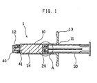
- FIGS. 1 and 2 are respectively a longitudinal cross section of a syringe in accordance with this embodiment, and an enlarged view of a portion defined by the circle of A in FIG. 1.
- the syringe 1 of this embodiment includes a tubular barrel 10 having an open proximal end 11, and a distal end with a fluid expelling passage 12 defined therein, a cylindrical seal 20 held within a barrel chamber a predetermined distance away from the open proximal end 11 in fluid-tight and axially-sliding engagement with the inner wall of the barrel chamber.
- a fluid held in the barrel chamber between the fluid expelling passage 12 of the barrel and the seal 20 is expelled from the barrel chamber to the outside via the fluid expelling passage 12.
- the barrel 10 may preferably be provided at its proximal end with a flange 13 radially and outwardly projecting from the open proximal end 11 and at its distal end with an arrangement enabling a piecing element such as a needle cannula to be attached to the distal end of the barrel 10.
- the syringe 1 may preferably be provided with a plunger rod 30 having a proximal end projecting proximally from the proximal end of the barrel, and a distal end interconnected to a proximal end of the seal so as to form a syringe assembly.
- reference numerals 40 and 41 respectively represent a cap for sealing a medical fluid and the medical fluid, both of which are prepared for a pre-filling syringe.
- the seal 20 defines at least two diametrically enlarged portions 21 at axially spaced apart portions of the seal, and a concave portion 22 positioned between adjacent diametrically enlarged portions of the at least two diametrically enlarged portions.
- the diametrically enlarged portions each are larger in diameter than the inner diameter of the barrel chamber 14 so as to become in abutment with the inner wall of the barrel chamber 14 under compressed and deformed states, thereby enabling the seal to exhibit a fluid-tight characteristic.
- the concave portion 22 is smaller in diameter than the inner diameter of the barrel chamber 14, and hence defines a clearance between the concave portion 22 of the seal and the inner wall of the barrel chamber 14.
- the concave portion 22 may be in the form of an annular groove extending around the circumferential periphery of the seal, or a plurality of cavities defined around the circumferential periphery of the seal with predetermined spaces.
- annular concave portion as illustrated in FIGS. 1 and 2.
- each diametrically enlarged portion 21 is illustrated as being diametrically smaller than the barrel chamber 14 so as to clearly show the existence of lubricant film 90a at interfaces between the diametrically enlarged portions and the inner wall of the barrel chamber 14.
- the diametrically enlarged portions 21 are radially compressed into tight engagement with the inner wall of the barrel chamber 14 with the lubricant film 90a existing at the interfaces therebetween.
- lubricant film 90a exists only at the interfaces between the inner wall of the barrel chamber 14 and the circumferential peripheries of the diametrically enlarged portions 21, and a lubricant 90 is filled in the clearance defined by the concave portion 22 of the seal and the inner wall of the barrel chamber 14, it is possible to prevent the medical fluid held in the barrel from contacting the lubricant, and simultaneously improve the slidability of the seal 20.
- the medical fluid held in the barrel chamber constantly contacts the lubricant, resulting in a high possibility of the elusion of the lubricant into the medical fluid.
- a barrel formed from plastic increases the possibility of the elusion of the lubricant since the lubricant cannot be baked on the surface of the barrel formed from plastic.
- FIG. 3 is a schematic view of the apparatus.
- the apparatus 100 includes a barrel retaining unit 50, a seal detent unit 60 and a thrusting unit 70.
- the barrel retaining unit 50 includes a first supporting plate 51 horizontally supported on a vertically standing main rod 80, and a retaining member 52 supported on the first supporting plate 51.
- the first supporting plate 51 may be supported on a frame (not shown).
- the retaining member 52 includes a tubular portion with a through-hole 52a therein extending in parallel with the axis of the main rod 80, and a flange 52b extending horizontally from the tubular portion.
- the barrel 10 is inserted into the through-hole 52a to be retained therein so that the barrel chamber 14 is positioned in parallel with the main rod 80, and the open proximal end 11 of the barrel 10 is upwardly directed.
- the barrel retaining member 52 is supported on the first supporting plate 51 via the flange 52b.
- the seal detent unit 60 disposed above the barrel retaining unit 50 includes a main piston 61 reciprocable along the main rod 80, a second supporting plate 62 horizontally supported on the main piston 61, an intermediate rod 63 vertically supported on the second supporting plate, and a detent member 64 supported above the retaining member 52 and below the second supporting plate 62 via the intermediate rod.
- the detent member 64 includes a trunk portion 64a, a diametrically smaller tubular portion 64b extending downwardly from the trunk portion 64b with a stepped portion 64c, and defines therein a through-hole 64e that is coaxially alignable with the barrel chamber 14 of the barrel to be retained within the retaining member 52, and includes at its lower side a trunk portion 64a that is accompanied by a decrease in diameter at a stepped portion 64c and terminates in a diametrically smaller tubular portion 64b.
- the diametrically smaller tubular portion 64b has the outer diameter smaller than the inner diameter of the barrel chamber 14, and hence is capable of plunging into the barrel chamber 14 via downward movement of the main piston 61.
- the inner wall of the detent member 64 may preferably have a tapered cross section so that the through-hole 64e becomes smaller in diameter as it advances downwards, enabling the detent member 64 to hold the seal 20 at a predetermined detent position within the through-hole 64e.
- the trunk portion 64a defines therein a passage 64d in communication between the detent position of the through-hole and the outside of the detent member 64 so that lubricant can be fed from the outside via the passage to be applied on the circumferential periphery of each diametrically enlarged portion 21 of the seal and to be filled in the concave portion 22 of the seal.
- the thrusting unit 70 includes a subsidiary rod 71 supported on the second supporting plate 62 so as to be positioned above the seal detent unit 60, and a thrusting member 72 reciprocable along the subsidiary rod.
- the subsidiary rod 71 is disposed so as to be coaxially aligned with the through-hole 64e of the detent member 64, and more specifically with the barrel chamber 14 of the barrel to be retained within the retaining member 52.
- the thrusting member 72 has a lower portion with its outer diameter smaller than the outer diameter of the seal 20, so that the seal 20 held within the detent member 64 can be moved downwards and forced out of the detent member 64 via an opening of the diametrically smaller tubular portion 64b by moving the thrusting member 72 downwards.
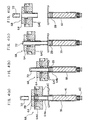
- FIGS. 4 (a) to 4 (d) show the respective steps of manufacturing the syringes by using the apparatus.
- the seal 20 is positioned at the detent position of the through-hole 64a of the detent member 64.
- Lubricant is, then, applied to the circumferential periphery of each diametrically enlarged portion 21 of the seal, and filled within the concave portion 22 (FIG. 4 (a)).
- the main piston 61 is, then, slid downwards to move the entirety of the seal detent unit 60 downwards, thereby plunging the diametrically smaller tubular portion 64b of the detent member into the barrel chamber 14.
- the thrusting unit 70 is then slid downwards to thrust the seal 20 to the lower end of the diametrically smaller tubular portion 64b via the thrusting member 72 (FIG. 4 (b)).
- the seal detent unit 60 is, then, moved upwards as the thrusting member 72 remains in the position of FIG. 4 (b), so that the seal 20 is forced into the barrel chamber 14 (FIG. 4 (c)).
- the main piston 61 is, then, moved upwards to move the thrusting member 72 upwards (FIG. 4 (d)), so that the barrel 10 with the seal 20 therein can be withdrawn from the barrel retaining unit 50.
- the syringe having an arrangement where the seal 20 has been forced into the barrel chamber 14 and held within the barrel chamber a predetermined distance away from the open proximal end 11 of the barrel 10, lubricant is not applied onto the inner wall of the barrel chamber 14 with the exception of the portion where the seal 20 is held, the lubricant film 90a exists only at the interfaces between the inner wall of the barrel chamber 14 and the diametrically enlarged portions 21 of the seal, and the lubricant 90 is filled in the clearance defined by the inner wall of the barrel chamber 14 and the concave portion 22 of the seal. Further, in accordance with this apparatus, it is possible to easily vary a seal holding position in the barrel chamber 14 by, for example, varying the length of the diametrically smaller tubular portion 64b of the detent member 64.
- the lower terminal point of the motion of the seal detent unit 60 is regulated by abutment between the stepped portion 64c of the detent member and the upper end of the barrel 10.
- the regulation of the terminal point is not necessarily accomplished by this arrangement, and hence can be accomplished by various arrangements, for example, by attaching a spacer on the first supporting plate 51.
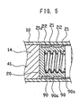
- FIG. 5 a second preferred embodiment of the present invention will be hereinafter described with reference to FIG. 5, in which corresponding or identical parts to those of the first embodiment have been given the same reference characters to omit a detailed description thereof.
- the syringe of this embodiment is configured and dimensioned so that the lubricant film 90a does not exist at the interface between the circumferential periphery of a diametrically enlarged portion 21a that is distally positioned and the inner wall of the barrel chamber 14.
- This diametrically enlarged portion 21a may preferably be configured to become thinner, thereby preventing deterioration of the slidability of the seal 20 due to a frictional resistance caused between the circumferential periphery of the diametrically enlarged portion 21a and the inner wall of the barrel chamber 14.
- the diametrically enlarged portion 21a is illustrated in FIG. 5 as being larger in diameter than the other diametrically enlarged portions so as to clearly show the existence of the lubricant film 90a at interfaces between the diametrically enlarged portions 21 and the inner wall of the barrel chamber 14.
- the seal 20 is preferably configured so that the diametrically enlarged portion 21a becomes slightly larger in diameter than the inner diameter of the syringe, and the other diametrically enlarged portions 21 each become larger in diameter than the diametrically enlarged portion 21a.
- the syringe of this embodiment can prevent the mixture of the lubricant into the medical fluid in a more effective manner as compared with the syringe of the first embodiment, as maintaining the fluid-tight characteristic and maintaining the slidability of the seal 20 to some extent.
- the diametrically enlarged portion 21a of this embodiment completely isolates the lubricant from the medical fluid, thereby preventing the elusion of the lubricant into the medical fluid.
- the apparatus described in the first embodiment can be used in manufacturing the syringe of this embodiment by controlling the detent position of the seal 20 within the detent member 64.
- Example 1 the testing was conducted to measure the number of fragments of a silicone coat as silicone foreign matters that fall into a medical fluid filled in the syringe by shaking or an autoclave treatment.
- the number of foreign matters fallen from the syringe with no silicone coating thereon has been measured so as to eliminate any influences caused by foreign matters excluding silicone.
- the testing method is as follows:
- the testing method is as follows:
- syringes formed from glass with silicone coatings applied onto their respective inner walls were prepared.
- the numbers of fragments of a silicone coat as foreign matters were measured and determined under the same conditions of the testing as those of this example, and the test results for the comparative examples will also be shown in TABLES 1 and 2.
- the details of the prepared syringes are as follows:
- Example 2 the testing was conducted to confirm the slidability of the seal.
- the load required for the initial sliding movement of the seal initial sliding resistance value
- the maximum load required for expelling the fluid maximum sliding resistance value
- the respective loads were measured by using the syringe of the first embodiment formed from plastic was used, in which the seal having a diameter of 15 mm, a height of 10 mm, and three larger diameter portions was forced into the syringe, and was filled with dust-free distilled water of 5 ml.
- initial load resistance value was measured under the same conditions applied in this Example by using commercially available disposable syringes F to J, each having silicone applied onto the entire surface of the inner wall thereof.
- the measured results are shown in TABLE 5.
- initial sliding resistance value maximum sliding resistance value (gf) (gf) Sample F 1196 ⁇ 0 Sample G 633 ⁇ 0 Sample H 1270 ⁇ 0 Sample I 519 ⁇ 0 Sample J 696 ⁇ 0 Testing Device: Shimazu Auto Graph S-500 Sliding Speed: 25 mm/min.
- each syringe according to the present invention exhibit the same degree of slidability as that of each conventional disposable syringe with silicone applied onto the entire surface of its inner wall.
Landscapes
- Health & Medical Sciences (AREA)
- Vascular Medicine (AREA)
- Engineering & Computer Science (AREA)
- Anesthesiology (AREA)
- Biomedical Technology (AREA)
- Heart & Thoracic Surgery (AREA)
- Hematology (AREA)
- Life Sciences & Earth Sciences (AREA)
- Animal Behavior & Ethology (AREA)
- General Health & Medical Sciences (AREA)
- Public Health (AREA)
- Veterinary Medicine (AREA)
- Infusion, Injection, And Reservoir Apparatuses (AREA)
Claims (1)
- Vorrichtung zur Herstellung einer Spritze mit:wobei die Vorrichtung ausgebildet ist, um die folgenden Verfahrensschritte auszuführen:einem rohrförmigen Behälter (10), welcher ein offenes proximales Ende (11), ein distales Ende mit einem darin definierten Durchgang (12) zum Ausstoßen eines Fluids und eine Zylinderkammer aufweist;einer Dichtung (20), welche innerhalb der Zylinderkammer mit einem vorbestimmten Abstand von dem offenen proximalen Ende (11) beabstandet in einem fluiddichten und axial verschiebbaren Eingriff mit der Zylinderkammer angeordnet ist, wobei die Dichtung (20) wenigstens zwei diametrisch vergrößerte Abschnitte als axial voneinander beabstandete Abschnitte auf der Dichtung (20), damit sich diese jeweils in Anlage mit der inneren Wand der Zylinderkammer befinden, und einen konkaven Abschnitt (22) zwischen benachbarten diametrisch vergrößerten Abschnitten der wenigstens zwei diametrisch vergrößerten Abschnitte (21) zum Definieren einer Lücke relativ zu der inneren Wand der Zylinderkammer definiert, wobei ein Gleitfilm (90a) an Übergängen zwischen den wenigstens zwei diametrisch vergrößerten Abschnitten (21) der Dichtung (20) und der inneren Wand der Zylinderkammer vorgesehen ist, und wobei ein Gleitmittel (90) in die Lücke gefüllt ist, wobei die Vorrichtung umfasst:eine Behälterhalteeinheit (50) zum darin Halten des Behälters (10) der Spritze;eine Dichtungsanbringeinheit (60), wobei darin ein Durchgangsloch (64e) mit einem inneren Durchmesser, der im wesentlichen gleich dem äußeren Durchmesser der Dichtung (20) zum Halten der Dichtung (20) in einer Anbringposition innerhalb des Durchgangslochs (64e) ist, ein diametrisch kleinerer Rohrabschnitt (64b), in welchem ein offenes Ende des Durchgangslochs (64e) definiert ist, wobei der diametrisch kleinere Rohrabschnitt (64b) in die Zylinderkammer über das offene proximale Ende (11) des Behälters (10) eintauchen und eine vorbestimmte Entfernung beabstandet von dem offenen proximalen Ende (11) des Behälters (10) überschreiten kann, und ein Durchgang (64b) definiert ist in Verbindung zwischen der Anbringposition des Durchgangslochs (64e) und der Außenseite der Dichtungsanbringeinheit (60) zum Zuführen des Gleitmittels (90) von der Außenseite zu der Dichtung (20), welche in der Anbringposition des Durchgangslochs (64e) gehalten ist; undeine Schubeinheit (70) zum Drängen der Dichtung (20), welche innerhalb des Durchgangslochs (64e) der Dichtungsanbringeinheit (60) gehalten ist, aus dem Durchgangsloch (64e) über eine Öffnung des diametrisch kleineren Rohrabschnitts (64b) der Dichtungsanbringeinheit (60) heraus;der diametrisch kleinere Rohrabschnitt (64b) der Dichtungsanbringeinheit (60) wird in die Zylinderkammer der Spritze eingetaucht, und anschließend wird die Dichtung (20), auf deren wenigstens zwei diametrisch vergrößerten Abschnitte (21) das Gleitmittel (21) aufgebracht und in die Lücke über den Durchgang (64d) gefüllt wird, in die Zylinderkammer durch die Schubeinheit (70) gedrängt, da der diametrisch kleinere Rohrabschnitt (64b) innerhalb der Zylinderkammer verbleibt.
Applications Claiming Priority (3)
| Application Number | Priority Date | Filing Date | Title |
|---|---|---|---|
| JP11921998A JP4132208B2 (ja) | 1998-04-28 | 1998-04-28 | 注射器用容器の製造装置及び注射器用容器の製造方法 |
| JP11921998 | 1998-04-28 | ||
| EP99107396A EP0965354B1 (de) | 1998-04-28 | 1999-04-26 | Spritze |
Related Parent Applications (1)
| Application Number | Title | Priority Date | Filing Date |
|---|---|---|---|
| EP99107396.6 Division | 1999-04-26 |
Publications (2)
| Publication Number | Publication Date |
|---|---|
| EP1325760A1 EP1325760A1 (de) | 2003-07-09 |
| EP1325760B1 true EP1325760B1 (de) | 2004-12-08 |
Family
ID=14755913
Family Applications (2)
| Application Number | Title | Priority Date | Filing Date |
|---|---|---|---|
| EP99107396A Expired - Lifetime EP0965354B1 (de) | 1998-04-28 | 1999-04-26 | Spritze |
| EP03007401A Expired - Lifetime EP1325760B1 (de) | 1998-04-28 | 1999-04-26 | Vorrichtung zur Herstellung einer Spritze |
Family Applications Before (1)
| Application Number | Title | Priority Date | Filing Date |
|---|---|---|---|
| EP99107396A Expired - Lifetime EP0965354B1 (de) | 1998-04-28 | 1999-04-26 | Spritze |
Country Status (4)
| Country | Link |
|---|---|
| US (2) | US6162200A (de) |
| EP (2) | EP0965354B1 (de) |
| JP (1) | JP4132208B2 (de) |
| DE (2) | DE69922556T2 (de) |
Families Citing this family (29)
| Publication number | Priority date | Publication date | Assignee | Title |
|---|---|---|---|---|
| US6093175A (en) * | 1998-06-05 | 2000-07-25 | Becton Dickinson And Company | Localized lubrication of syringe barrels and stoppers |
| US6840938B1 (en) * | 2000-12-29 | 2005-01-11 | Intuitive Surgical, Inc. | Bipolar cauterizing instrument |
| US20050010175A1 (en) * | 2003-02-27 | 2005-01-13 | Beedon Daniel E. | Piston assembly for syringe |
| US7666169B2 (en) | 2003-11-25 | 2010-02-23 | Medrad, Inc. | Syringe and syringe plungers for use with medical injectors |
| USD1031029S1 (en) | 2003-11-25 | 2024-06-11 | Bayer Healthcare Llc | Syringe plunger |
| JP4460278B2 (ja) * | 2003-12-17 | 2010-05-12 | 株式会社大協精工 | 注射器用密封栓及びプレフィルド注射器 |
| US7749202B2 (en) | 2005-08-29 | 2010-07-06 | West Pharmaceutical Services, Inc. | Dual material plunger tip for use with a syringe |
| EP1797920B1 (de) * | 2005-12-15 | 2011-10-19 | Sulzer Mixpac AG | Vorrichtung zur Aufnahme und zum Austragen einer fliessfähigen Substanz |
| US8926569B2 (en) | 2006-03-15 | 2015-01-06 | Bayer Medical Care Inc. | Plunger covers and plungers for use in syringes and methods of fabricating plunger covers and plungers for use in syringes |
| US8038656B2 (en) | 2006-09-29 | 2011-10-18 | Tyco Healthcare Group Lp | Detachable plunger rod syringe |
| USD1002840S1 (en) | 2007-03-14 | 2023-10-24 | Bayer Healthcare Llc | Syringe plunger |
| USD942005S1 (en) | 2007-03-14 | 2022-01-25 | Bayer Healthcare Llc | Orange syringe plunger cover |
| USD847985S1 (en) | 2007-03-14 | 2019-05-07 | Bayer Healthcare Llc | Syringe plunger cover |
| CN101983080B (zh) * | 2008-04-01 | 2013-12-25 | 生化学工业株式会社 | 药液排放部密封盖 |
| JP5318687B2 (ja) * | 2009-07-21 | 2013-10-16 | 大和特殊硝子株式会社 | 注射器用栓体とこれを装着した注射器および注射器用栓体の打栓方法 |
| EP2673025B1 (de) * | 2011-02-09 | 2025-01-08 | Becton, Dickinson and Company | Verbesserungen an infusionssystemen |
| US9873098B2 (en) * | 2012-05-30 | 2018-01-23 | Mitsui Chemicals, Inc. | Three-component mixing apparatus and three-component mixing adhesive kit |
| US9174003B2 (en) * | 2012-09-28 | 2015-11-03 | Bayer Medical Care Inc. | Quick release plunger |
| JP6108823B2 (ja) * | 2012-12-26 | 2017-04-05 | 大成化工株式会社 | シリンジ |
| US9875904B2 (en) | 2013-01-15 | 2018-01-23 | Mitsubishi Gas Chemical Company, Inc. | Silicon etching liquid, silicon etching method, and microelectromechanical element |
| WO2015142995A1 (en) | 2014-03-19 | 2015-09-24 | Bayer Medical Care Inc. | System for syringe engagement to an injector |
| CN107635527B (zh) | 2015-03-10 | 2021-04-23 | 里珍纳龙药品有限公司 | 无菌刺穿系统和方法 |
| US9480797B1 (en) | 2015-10-28 | 2016-11-01 | Bayer Healthcare Llc | System and method for syringe plunger engagement with an injector |
| HUE063479T2 (hu) | 2017-01-06 | 2024-01-28 | Bayer Healthcare Llc | Fecskendõ dugattyú dinamikus tömítéssel |
| IL308643B2 (en) | 2017-05-05 | 2025-02-01 | Regeneron Pharma | Auto-injector |
| ES2939249T3 (es) | 2018-02-27 | 2023-04-20 | Bayer Healthcare Llc | Mecanismo de acoplamiento de émbolo de jeringa |
| CN110192925A (zh) * | 2019-05-23 | 2019-09-03 | 爱几度(深圳)科技有限公司 | 一种洗牙器及用于洗牙器的抽水泵 |
| AR122637A1 (es) | 2020-06-18 | 2022-09-28 | Bayer Healthcare Llc | Sistema y método para el acoplamiento del émbolo de la jeringa con un inyector |
| USD1007676S1 (en) | 2021-11-16 | 2023-12-12 | Regeneron Pharmaceuticals, Inc. | Wearable autoinjector |
Family Cites Families (11)
| Publication number | Priority date | Publication date | Assignee | Title |
|---|---|---|---|---|
| DE3045950C2 (de) * | 1980-12-05 | 1984-03-01 | Sortimat Creuz & Co Gmbh, 7057 Winnenden | Verfahren und Vorrichtung zum Silikonisieren reibend beanspruchter Flächen von Spritzenzylindern |
| JPS61502099A (ja) * | 1984-05-16 | 1986-09-25 | コスモノ−ル ソシエテ アノニム | 単量予充てん式注射器の製造方法および装置 |
| JPH0747045B2 (ja) * | 1986-10-15 | 1995-05-24 | 株式会社大協精工 | 積層した注射器用滑栓 |
| JPH0534669Y2 (de) * | 1988-03-16 | 1993-09-02 | ||
| US5282792A (en) * | 1992-07-21 | 1994-02-01 | Becton, Dickinson And Company | Syringe having two component barrel |
| US5353691A (en) * | 1993-04-14 | 1994-10-11 | Habley Medical Technology Corp. | Self-lubricating piston for pharmaceutical container |
| JP2584722B2 (ja) * | 1994-06-21 | 1997-02-26 | 株式会社崇洋堂 | 注射器 |
| US5607400A (en) * | 1995-05-19 | 1997-03-04 | Becton, Dickinson And Company | Pre-fillable syringe and stopper assembly therefor |
| US5687542A (en) * | 1995-08-22 | 1997-11-18 | Medrad, Inc. | Isolation module for molding and packaging articles substantially free from contaminants |
| DE29516282U1 (de) * | 1995-10-13 | 1995-12-07 | Hoechst Ag, 65929 Frankfurt | Kolbenstopfen für Spritzenzylinder |
| US5951527A (en) * | 1998-05-05 | 1999-09-14 | Daikyo Seiko, Ltd | Sliding piston for syringe |
-
1998
- 1998-04-28 JP JP11921998A patent/JP4132208B2/ja not_active Expired - Lifetime
-
1999
- 1999-04-22 US US09/296,345 patent/US6162200A/en not_active Expired - Lifetime
- 1999-04-26 EP EP99107396A patent/EP0965354B1/de not_active Expired - Lifetime
- 1999-04-26 DE DE69922556T patent/DE69922556T2/de not_active Expired - Lifetime
- 1999-04-26 EP EP03007401A patent/EP1325760B1/de not_active Expired - Lifetime
- 1999-04-26 DE DE69919784T patent/DE69919784T2/de not_active Expired - Lifetime
-
2000
- 2000-07-12 US US09/614,349 patent/US6425886B1/en not_active Expired - Lifetime
Also Published As
| Publication number | Publication date |
|---|---|
| JPH11309210A (ja) | 1999-11-09 |
| EP0965354B1 (de) | 2004-09-01 |
| EP1325760A1 (de) | 2003-07-09 |
| DE69922556D1 (de) | 2005-01-13 |
| DE69922556T2 (de) | 2006-01-05 |
| DE69919784D1 (de) | 2004-10-07 |
| EP0965354A2 (de) | 1999-12-22 |
| US6162200A (en) | 2000-12-19 |
| JP4132208B2 (ja) | 2008-08-13 |
| EP0965354A3 (de) | 2000-03-22 |
| DE69919784T2 (de) | 2005-09-22 |
| US6425886B1 (en) | 2002-07-30 |
Similar Documents
| Publication | Publication Date | Title |
|---|---|---|
| EP1325760B1 (de) | Vorrichtung zur Herstellung einer Spritze | |
| DE69605710T2 (de) | Vorfuellbare Spritze und Stopfer dafür | |
| DE69306006T2 (de) | Verfahren zur terminalen Dampfsterilisation | |
| DE69320845T2 (de) | Vorgefüllte Plastikspritzen, -behälter und -fläschchen und Methode zu deren abschliessender Sterilisierung | |
| US6746430B2 (en) | Low silicone plastic prefillable syringe | |
| JP5412276B2 (ja) | コーティングシステム、同コーティングシステムを用いた物品および組立体、ならびにスティクションを低減する方法 | |
| US5411488A (en) | Pre-filled syringe and pre-filled cartridge having an improved plunger and plunger rod for reducing syringing force | |
| EP0758255B1 (de) | Reibungsfreie spritze | |
| US7141042B2 (en) | Low silicone glass prefillable syringe | |
| JP7187321B2 (ja) | 予め充填された非ガラスの容器を製造するための方法 | |
| KR20240035538A (ko) | 가교결합된 실리콘층을 갖는 팁 커버 및 그러한 팁 커버를 형성하는 방법 | |
| EP1064037B1 (de) | Spritze mit schmierung aus silikonpolymeren | |
| WO2021206360A1 (ko) | 토출 속도 조절이 용이하고 안정한 보툴리눔 독소 사전충전된 주사기 제형 | |
| KR102404217B1 (ko) | 토출 속도 조절이 용이하고 안정한 보툴리눔 독소 사전충전된 주사기 제형 | |
| KR100373886B1 (ko) | 주사기용 미끄럼이동 밸브, 주사기, 및 키트제제 | |
| JP2024520584A (ja) | 医療用注射器用低シリコーンオイルシステムの製造方法 | |
| EP0689847A1 (de) | Spritzeneinheit | |
| EP4539909A1 (de) | Kolbenstange und kolbenstangenadapter für kolben | |
| EP0935476A1 (de) | Spritze mit spritzenstopfen aus polyethylen | |
| EP4623959A1 (de) | Spritze mit abgestutzter nadel und gebackener silikonbeschichtung sowie herstellungsverfahren dafür | |
| KR20210125354A (ko) | 토출 속도 조절이 용이하고 안정한 보툴리눔 독소 사전충전된 주사기 제형 | |
| EP4599867A1 (de) | Färbemittel zur silikonisierung von spritzen | |
| DE69929706T2 (de) | Dichtung für eine gefüllte spritze | |
| KR20210125358A (ko) | 토출 속도 조절이 용이하고 안정한 보툴리눔 독소 사전충전된 주사기 제형 |
Legal Events
| Date | Code | Title | Description |
|---|---|---|---|
| PUAI | Public reference made under article 153(3) epc to a published international application that has entered the european phase |
Free format text: ORIGINAL CODE: 0009012 |
|
| AC | Divisional application: reference to earlier application |
Ref document number: 0965354 Country of ref document: EP Kind code of ref document: P |
|
| AK | Designated contracting states |
Designated state(s): BE CH DE FR GB LI |
|
| 17P | Request for examination filed |
Effective date: 20030822 |
|
| AKX | Designation fees paid |
Designated state(s): DE FR GB |
|
| GRAP | Despatch of communication of intention to grant a patent |
Free format text: ORIGINAL CODE: EPIDOSNIGR1 |
|
| RTI1 | Title (correction) |
Free format text: APPARATUS FOR MANUFACTURING A SYRINGE |
|
| RTI1 | Title (correction) |
Free format text: APPARATUS FOR MANUFACTURING A SYRINGE |
|
| GRAS | Grant fee paid |
Free format text: ORIGINAL CODE: EPIDOSNIGR3 |
|
| GRAA | (expected) grant |
Free format text: ORIGINAL CODE: 0009210 |
|
| AC | Divisional application: reference to earlier application |
Ref document number: 0965354 Country of ref document: EP Kind code of ref document: P |
|
| AK | Designated contracting states |
Kind code of ref document: B1 Designated state(s): DE FR GB |
|
| REG | Reference to a national code |
Ref country code: GB Ref legal event code: FG4D |
|
| REF | Corresponds to: |
Ref document number: 69922556 Country of ref document: DE Date of ref document: 20050113 Kind code of ref document: P |
|
| PLBE | No opposition filed within time limit |
Free format text: ORIGINAL CODE: 0009261 |
|
| STAA | Information on the status of an ep patent application or granted ep patent |
Free format text: STATUS: NO OPPOSITION FILED WITHIN TIME LIMIT |
|
| 26N | No opposition filed |
Effective date: 20050909 |
|
| ET | Fr: translation filed | ||
| REG | Reference to a national code |
Ref country code: FR Ref legal event code: PLFP Year of fee payment: 18 |
|
| REG | Reference to a national code |
Ref country code: FR Ref legal event code: PLFP Year of fee payment: 19 |
|
| REG | Reference to a national code |
Ref country code: FR Ref legal event code: PLFP Year of fee payment: 20 |
|
| PGFP | Annual fee paid to national office [announced via postgrant information from national office to epo] |
Ref country code: GB Payment date: 20180329 Year of fee payment: 20 |
|
| PGFP | Annual fee paid to national office [announced via postgrant information from national office to epo] |
Ref country code: FR Payment date: 20180327 Year of fee payment: 20 |
|
| PGFP | Annual fee paid to national office [announced via postgrant information from national office to epo] |
Ref country code: DE Payment date: 20180410 Year of fee payment: 20 |
|
| REG | Reference to a national code |
Ref country code: DE Ref legal event code: R071 Ref document number: 69922556 Country of ref document: DE |
|
| REG | Reference to a national code |
Ref country code: GB Ref legal event code: PE20 Expiry date: 20190425 |
|
| PG25 | Lapsed in a contracting state [announced via postgrant information from national office to epo] |
Ref country code: GB Free format text: LAPSE BECAUSE OF EXPIRATION OF PROTECTION Effective date: 20190425 |