EP1326021A1 - Brennstoffzufuhrvorrichtung und dafür verwendeter brennstofffilter - Google Patents
Brennstoffzufuhrvorrichtung und dafür verwendeter brennstofffilter Download PDFInfo
- Publication number
- EP1326021A1 EP1326021A1 EP01967705A EP01967705A EP1326021A1 EP 1326021 A1 EP1326021 A1 EP 1326021A1 EP 01967705 A EP01967705 A EP 01967705A EP 01967705 A EP01967705 A EP 01967705A EP 1326021 A1 EP1326021 A1 EP 1326021A1
- Authority
- EP
- European Patent Office
- Prior art keywords
- fuel
- filter
- pipe
- disposed
- joint
- Prior art date
- Legal status (The legal status is an assumption and is not a legal conclusion. Google has not performed a legal analysis and makes no representation as to the accuracy of the status listed.)
- Granted
Links
Images




Classifications
-
- F—MECHANICAL ENGINEERING; LIGHTING; HEATING; WEAPONS; BLASTING
- F02—COMBUSTION ENGINES; HOT-GAS OR COMBUSTION-PRODUCT ENGINE PLANTS
- F02M—SUPPLYING COMBUSTION ENGINES IN GENERAL WITH COMBUSTIBLE MIXTURES OR CONSTITUENTS THEREOF
- F02M37/00—Apparatus or systems for feeding liquid fuel from storage containers to carburettors or fuel-injection apparatus; Arrangements for purifying liquid fuel specially adapted for, or arranged on, internal-combustion engines
- F02M37/0047—Layout or arrangement of systems for feeding fuel
-
- F—MECHANICAL ENGINEERING; LIGHTING; HEATING; WEAPONS; BLASTING
- F02—COMBUSTION ENGINES; HOT-GAS OR COMBUSTION-PRODUCT ENGINE PLANTS
- F02M—SUPPLYING COMBUSTION ENGINES IN GENERAL WITH COMBUSTIBLE MIXTURES OR CONSTITUENTS THEREOF
- F02M37/00—Apparatus or systems for feeding liquid fuel from storage containers to carburettors or fuel-injection apparatus; Arrangements for purifying liquid fuel specially adapted for, or arranged on, internal-combustion engines
- F02M37/22—Arrangements for purifying liquid fuel specially adapted for, or arranged on, internal-combustion engines, e.g. arrangements in the feeding system
-
- F—MECHANICAL ENGINEERING; LIGHTING; HEATING; WEAPONS; BLASTING
- F02—COMBUSTION ENGINES; HOT-GAS OR COMBUSTION-PRODUCT ENGINE PLANTS
- F02M—SUPPLYING COMBUSTION ENGINES IN GENERAL WITH COMBUSTIBLE MIXTURES OR CONSTITUENTS THEREOF
- F02M37/00—Apparatus or systems for feeding liquid fuel from storage containers to carburettors or fuel-injection apparatus; Arrangements for purifying liquid fuel specially adapted for, or arranged on, internal-combustion engines
- F02M37/20—Apparatus or systems for feeding liquid fuel from storage containers to carburettors or fuel-injection apparatus; Arrangements for purifying liquid fuel specially adapted for, or arranged on, internal-combustion engines characterised by means for preventing vapour lock
-
- F—MECHANICAL ENGINEERING; LIGHTING; HEATING; WEAPONS; BLASTING
- F02—COMBUSTION ENGINES; HOT-GAS OR COMBUSTION-PRODUCT ENGINE PLANTS
- F02M—SUPPLYING COMBUSTION ENGINES IN GENERAL WITH COMBUSTIBLE MIXTURES OR CONSTITUENTS THEREOF
- F02M37/00—Apparatus or systems for feeding liquid fuel from storage containers to carburettors or fuel-injection apparatus; Arrangements for purifying liquid fuel specially adapted for, or arranged on, internal-combustion engines
- F02M37/22—Arrangements for purifying liquid fuel specially adapted for, or arranged on, internal-combustion engines, e.g. arrangements in the feeding system
- F02M37/32—Arrangements for purifying liquid fuel specially adapted for, or arranged on, internal-combustion engines, e.g. arrangements in the feeding system characterised by filters or filter arrangements
-
- F—MECHANICAL ENGINEERING; LIGHTING; HEATING; WEAPONS; BLASTING
- F02—COMBUSTION ENGINES; HOT-GAS OR COMBUSTION-PRODUCT ENGINE PLANTS
- F02M—SUPPLYING COMBUSTION ENGINES IN GENERAL WITH COMBUSTIBLE MIXTURES OR CONSTITUENTS THEREOF
- F02M55/00—Fuel-injection apparatus characterised by their fuel conduits or their venting means; Arrangements of conduits between fuel tank and pump F02M37/00
Definitions
- the present invention relates to a fuel supply device and a fuel filter, and especially relates to a fuel supply device that pressurizes fuel and supplies the fuel as fine particles to an internal combustion engine, and a fuel filter that is utilized for this fuel supply device.
- Fig. 8 the structure shown in Fig. 8 is well-known as this kind of fuel supply device.
- fuel F which is stored in a fuel tank 1 is introduced to a fuel pump 3 through a fuel filter 2 by which the fuel F is filtered.
- the fuel F is atomized and injected to an intake pipe or a combustion chamber of an internal combustion engine by a fuel injection nozzle 4 while the fuel F is pressurized to or over a specific pressure by the fuel pump 3 and supplied to the fuel injection nozzle 4.
- the numerical 5 is a pressure regulator which is disposed between the fuel pump 3 and the fuel injection nozzle 4, and regulates the pressure of the fuel F that is supplied to the fuel injection nozzle to a specific pressure.
- the pressure of the fuel F is regulated by returning excess fuel F to the fuel tank 1 through a return pipe 6.
- the inside of the fuel filter 2 is divided by a filter member (a filter paper etc.) 7 into two rooms which are the upstream side and the downstream side, namely, upstream room 8 and downstream room 9.
- a filter member a filter paper etc.
- the upstream room 8 of the fuel filter 2 is connected to the inside of the fuel tank 1 which is located above and is filled up with the fuel F, so as to receive pressure head equivalent to the fuel level height of the fuel F in the fuel tank 1.
- Vapor is generated in the fuel F due to the depression at the time when the fuel F is moved by the pressure balance from the upstream room 8 to the downstream room 9, or due to heating of the fuel F in the fuel supply passage by the environmental temperature increase.
- the present invention is devised in the light of such conventional problems.
- the purpose of the present invention is to provide a fuel supply device and a fuel filter that is utilized to the fuel supply device, which can ensure the fuel discharging amount of the fuel pump by satisfactory removing of vapor which is generated in the fuel sucked by the fuel pump.
- the present invention of claim 1 is a fuel supply device to pressurize and supply fuel stored in a fuel tank, which comprises a fuel supply pipe that forms a supply passage for the fuel, a fuel filter to filter the fuel disposed at the midway of the fuel supply pipe and below the fuel tank, a fuel pump to pressure-feed the fuel disposed at the downstream side than the fuel filter, and a venting pipe to connect the downstream side of the fuel filter and an upper air-space of the fuel tank.
- the present invention of claim 2 is the fuel supply device according to claim 1, wherein a suction portion of the fuel pump is disposed below a fuel discharge portion of the fuel filter.
- the present invention of claim 3 is the fuel supply device according to claim 1 or claim 2, which further comprises a pressure regulator disposed at the downstream side of the fuel supply pipe than the fuel pump to adjust the pressure of the fuel discharged from the fuel pump, a return pipe disposed at the pressure regulator to return surplus fuel to the fuel tank, wherein the return pipe communicates with the midway of the venting pipe at the position above the pressure regulator.
- the present invention of claim 4 is the fuel supply device according to claim 3, wherein the return pipe is connected to the venting pipe so that the angle which the return pipe forms with the venting pipe is upwardly acute.
- the present invention of claim 5 is a fuel filter which is utilized for the fuel supply device according to claim 1 through 4, which comprises a fuel filter main body, a filter member which divides the inside of the filter main body into an upstream room and a downstream room, a suction joint disposed at the upstream room of the fuel filter main body to communicate with the fuel tank, a supply joint disposed at the lower part of the downstream room of the fuel filter main body to communicate with the fuel pump, and a circulating joint disposed at the upper part of the downstream room of the fuel filter to communicate with an upper air-space of the fuel tank.
- the present invention of claim 6 is the fuel filter according to claim 5, wherein a return joint to which the return pipe of the pressure regulator is connected is disposed at the circulating joint.
- the present invention of claim 7 is the fuel filter according to claim 6, wherein the return joint is connected to the circulating joint so that the angle which the return joint forms with the circulating joint is upwardly acute.
- Fig. 1 is a system schematic showing an embodiment of the present invention.
- Fig. 2 is an external perspective view of a fuel filter showing an embodiment of the present invention.
- Fig. 3 is a longitudinal cross-sectional view of a fuel filter showing an embodiment of the present invention.
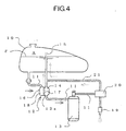
- Fig.4 is a system schematic showing the second embodiment of the present invention.
- Fig. 5 is an external perspective view of a fuel filter showing the second embodiment of the present invention.
- Fig. 6 is a longitudinal cross-sectional view of a fuel filter showing the second embodiment of the present invention.
- Fig. 7 is a longitudinal cross-sectional view of a fuel filter showing another embodiment of the present invention.
- Fig. 8 is a system schematic of a related art.
- Fig. 1 shows a general structure of a fuel supply device to pressurize and supply fuel F which is stored in a fuel tank 10, which comprises a fuel supply pipe 11 that forms a supply passage for the fuel F, a fuel filter 12 to filter the fuel F disposed at the midway of the fuel pipe 11 and below the fuel tank 10, a fuel pump 13 to pressure-feed the fuel F disposed at the downstream side than the fuel filterl2, and a venting pipe 15 to connect the downstream side (the downstream room 14) of the fuel filter 12 and an upper air-space A of the fuel tank 10.
- a fuel supply pipe 11 that forms a supply passage for the fuel F
- a fuel filter 12 to filter the fuel F disposed at the midway of the fuel pipe 11 and below the fuel tank 10
- a fuel pump 13 to pressure-feed the fuel F disposed at the downstream side than the fuel filterl2
- a venting pipe 15 to connect the downstream side (the downstream room 14) of the fuel filter 12 and an upper air-space A of the fuel tank 10.
- the fuel filter 12 consists of a fuel filter main body 16 and a filter member (a filter paper etc.) 17 which divides the fuel filter main body into an upstream room 18 and downstream room 14.
- the upstream room 18 communicates with a bottom portion of the fuel tank 10 through a suction joint 16a disposed at the upper part of the fuel filter main body 16, and a part of the fuel supply pipe 11 connected to the suction joint 16a.
- the downstream room 14 communicates with a suction portion 13a of the fuel pump 13 through a supply joint 16b disposed at a fuel discharge portion 12a of a bottom portion of the fuel filter main body 16, and a part of the fuel supply pipe 11 connected to the supply joint 16b.
- a circulating joint 16c to which the venting pipe 15 connects, is disposed upwardly at the upper part of the downstream room 14.
- the venting pipe 15 pierces the bottom portion of the fuel tank 10 and is inserted to the inside, so that the upper end portion locates at the upper air-space A.
- the fuel pump 13 is disposed so that the suction portion 13a positions below the fuel discharge portion 12a of the fuel filter 12.
- numeral 19 shows a fuel injection nozzle which atomizes the pressure-fed fuel F by the fuel pump 13 and injects to an intake pipe of a combustion chamber of an internal combustion engine (not shown in figures).
- a pressure regulator 20, which regulates the fuel F supplied to the fuel injection nozzle 19 to a specific pressure, is disposed at the midway of the fuel supply pipe 11 which connects the fuel injection nozzle 19 and the fuel pump 13.
- the pressure regulator 20 regulates the pressure of the fuel F supplied by the fuel pump, by returning excess amount of the fuel F to the fuel tank 10 through the return pipe 21.
- the fuel pump 13 After the fuel pump 13 is activated to supply the fuel F to an internal combustion engine, the fuel F in the fuel tank 10 flows into the upstream room 18 of the fuel filter 12 by its weight. The fuel F filtered by the filter member 17 flows into the downstream room 14 and is sucked to the fuel pump 13 which is disposed below.
- the fuel F sucked to the fuel pump 13 as described above is pressurized by the fuel pump 13 to or over a specific pressure, and is supplied to the fuel injection nozzle 19 after its pressure is regulated by the pressure regulator 20, and is atomized and injected to an intake pipe or a combustion chamber of an internal combustion engine by the fuel injection nozzle 19.
- the vapor B generated as described above is introduced into the downstream room 14 of the fuel filter 12, and gathers at its upper area, as shown in Fig. 3.
- the venting pipe 15 is connected to the upper area of the downstream room 14 through the circulating joint 16c, the vapor moves upwards with its buoyancy in the circulating joint 16c and the venting pipe 15.
- An air-lift pump is structured with the circulating joint 16c and venting pipe 15 where such movements of the vapor B occur, and by this pump, the vapor B is discharged to the upper air-space A of the fuel tank 10.
- the suction portion 13a of the fuel pump 13 is disposed below the discharge portion 12a of the fuel filter 12, the vapor generated at the vicinity and the inside of the fuel pump 13 is discharged with its buoyancy to the fuel tank 10 through the downstream room 14 and the venting pipe 15.
- the amount of the vapor B, which is mixed in the fuel F sucked to the fuel pump 13, is greatly reduced so that the degradation of the fuel pump 13 in fuel feeding amount (discharging amount) is prevented.
- the fuel supply device of the embodiment is characterized in that the return pipe 21 is connected to the midway of the venting pipe 15 above the pressure regulator 20, and the rest of the structure is the same as those of the aforementioned embodiment.
- the return joint 16d is disposed horizontally at the vicinity of the lower end portion of the circulating joint 16c.
- the top end portion of the return pipe 21 is connected to the return joint 16d, so as to be approximately orthogonal to the venting pipe 15 and to be approximately horizontal.
- the vapor B in the fuel F which is discharged from the pressure regulator 20, is introduced to the venting pipe 15 with the excess fuel F and returned to the fuel tank 10 through the venting pipe 15.
- shapes and dimensions etc. shown in the aforementioned embodiments are just examples, and are capable to be changed variously based on design requirements and so on.
- the return joint 16d itself is disposed to form the angle with the venting pipe upwardly acute, so that the return pipe can be connected as abovementioned.
- the angle which the excess fuel F and the vapor B flowed from the return pipe 21 forms with the flow direction of the venting pipe 15 can be acute, so that the entangling force by the excess fuel to the vapor B from the downstream room 14 is increased, and the removing capability of the vapor B is increased.
- vapor generated at the upstream of a fuel pump can be discharged to a fuel tank through a venting pipe, so that the amount of vapor sucked to the fuel pump is greatly reduced and the degradation of the fuel pump in feeding capacity can be prevented.
Landscapes
- Engineering & Computer Science (AREA)
- Chemical & Material Sciences (AREA)
- Combustion & Propulsion (AREA)
- Mechanical Engineering (AREA)
- General Engineering & Computer Science (AREA)
- Fuel-Injection Apparatus (AREA)
- Cooling, Air Intake And Gas Exhaust, And Fuel Tank Arrangements In Propulsion Units (AREA)
Applications Claiming Priority (3)
| Application Number | Priority Date | Filing Date | Title |
|---|---|---|---|
| JP2000284638 | 2000-09-20 | ||
| JP2000284638 | 2000-09-20 | ||
| PCT/JP2001/008054 WO2002025095A1 (en) | 2000-09-20 | 2001-09-17 | Fuel feeding device and fuel filter used for the device |
Publications (3)
| Publication Number | Publication Date |
|---|---|
| EP1326021A1 true EP1326021A1 (de) | 2003-07-09 |
| EP1326021A4 EP1326021A4 (de) | 2006-05-03 |
| EP1326021B1 EP1326021B1 (de) | 2009-02-25 |
Family
ID=18768816
Family Applications (1)
| Application Number | Title | Priority Date | Filing Date |
|---|---|---|---|
| EP01967705A Expired - Lifetime EP1326021B1 (de) | 2000-09-20 | 2001-09-17 | Brennstofffilter |
Country Status (6)
| Country | Link |
|---|---|
| US (1) | US6946071B2 (de) |
| EP (1) | EP1326021B1 (de) |
| KR (1) | KR100729252B1 (de) |
| CN (1) | CN100379974C (de) |
| DE (1) | DE60137787D1 (de) |
| WO (1) | WO2002025095A1 (de) |
Cited By (1)
| Publication number | Priority date | Publication date | Assignee | Title |
|---|---|---|---|---|
| EP1413740A4 (de) * | 2001-07-30 | 2009-01-21 | Mikuni Kogyo Kk | Dampfentfernungsvorrichtung für kraftstoffversorgungssystem eines verbrennungsmotors |
Families Citing this family (16)
| Publication number | Priority date | Publication date | Assignee | Title |
|---|---|---|---|---|
| CN1904343B (zh) * | 2005-07-26 | 2010-08-25 | 浙江飞亚电子有限公司 | 一种低压供油回路的汽液分离器 |
| JP2007056840A (ja) * | 2005-08-26 | 2007-03-08 | Yamaha Motor Co Ltd | エンジン装置における燃料タンクの燃料蒸気排出構造 |
| JP4864827B2 (ja) * | 2007-07-18 | 2012-02-01 | 愛三工業株式会社 | 燃料供給装置 |
| US8725427B2 (en) | 2008-01-22 | 2014-05-13 | Yong Gwan Won | Method and apparatus for estimating features of target materials by using kinetic change information |
| CN101311522B (zh) * | 2008-02-04 | 2010-12-01 | 浙江飞亚电子有限公司 | 一种滤清式汽液分离装置 |
| JP2010138776A (ja) * | 2008-12-11 | 2010-06-24 | Mitsubishi Electric Corp | 燃料供給装置 |
| JP5513271B2 (ja) * | 2010-06-15 | 2014-06-04 | 本田技研工業株式会社 | 車両の燃料供給装置 |
| JP5759778B2 (ja) * | 2011-04-26 | 2015-08-05 | 本田技研工業株式会社 | エンジン動力作業機 |
| KR101466222B1 (ko) | 2012-06-01 | 2014-12-01 | 주식회사 아이센스 | 정확도가 향상된 전기화학적 바이오센서 |
| US9089791B2 (en) | 2013-03-14 | 2015-07-28 | Cummins Ip, Inc. | Apparatus, method, and system for reductant filtration |
| CN104074649A (zh) * | 2013-03-28 | 2014-10-01 | 北汽福田汽车股份有限公司 | 对柴油机进油管路进行排气的装置及方法 |
| JP2014202088A (ja) * | 2013-04-02 | 2014-10-27 | ヤマハ発動機株式会社 | 燃料供給装置及び鞍乗型車両 |
| SE1651397A1 (en) | 2016-10-26 | 2018-04-03 | Scania Cv Ab | Fuel filter device, fuel tank, fuel system and a vehicle comprising the fuel filter device |
| CN107061082A (zh) * | 2017-02-17 | 2017-08-18 | 广西玉柴机器股份有限公司 | 电控共轨发动机无忧启动系统 |
| CN110735744B (zh) * | 2019-09-17 | 2020-10-23 | 上海蓝魂环保科技有限公司 | 一种具有过滤作用的船舶燃料油供应系统 |
| CN111502878B (zh) * | 2020-05-09 | 2021-06-25 | 三一重机有限公司 | 燃油滤清器和机械设备 |
Family Cites Families (28)
| Publication number | Priority date | Publication date | Assignee | Title |
|---|---|---|---|---|
| US1249939A (en) * | 1916-04-28 | 1917-12-11 | Wray Falwell | Vacuum fuel-feed system. |
| US3239064A (en) * | 1963-01-14 | 1966-03-08 | Acf Ind Inc | Filter with vapor bleed means |
| GB1216653A (en) * | 1966-11-22 | 1970-12-23 | Lucas Industries Ltd | Fuel supply systems for internal combustion engines |
| JPS5820373A (ja) | 1981-07-30 | 1983-02-05 | Mitsubishi Electric Corp | 狭開先溶接方法およびその装置 |
| JPS5984264A (ja) | 1982-11-06 | 1984-05-15 | Ricoh Co Ltd | 複写機 |
| JPS5984264U (ja) * | 1982-11-26 | 1984-06-07 | ヤンマーディーゼル株式会社 | エンジン作業機セツトのエア抜き装置 |
| JPS61184861A (ja) | 1985-02-12 | 1986-08-18 | Matsushita Electronics Corp | 半導体装置 |
| US4844704A (en) * | 1986-04-03 | 1989-07-04 | Honda Giken Kogyo Kabushiki Kaisha | Fuel pump assembly |
| JPS63170571A (ja) * | 1987-01-09 | 1988-07-14 | Mitsubishi Electric Corp | 直結形油回転真空ポンプの起動装置 |
| JPS63170571U (de) * | 1987-04-27 | 1988-11-07 | ||
| WO1990011444A1 (fr) * | 1989-03-29 | 1990-10-04 | Kabushiki Kaisha Komatsu Seisakusho | Appareil d'evacuation d'air pour circuit d'alimentation en carburant |
| GB8917872D0 (en) * | 1989-08-04 | 1989-09-20 | Lucas Ind Plc | Low pressure fuel supply system for a fuel injection fluid |
| DE4008609C1 (de) * | 1990-03-17 | 1991-03-07 | Mercedes-Benz Aktiengesellschaft, 7000 Stuttgart, De | |
| JPH0419659A (ja) * | 1990-05-14 | 1992-01-23 | Brother Ind Ltd | 画像記録装置 |
| JP2524675Y2 (ja) * | 1990-06-05 | 1997-02-05 | 株式会社クボタ | ディーゼルエンジンの自然流下式燃料供給装置 |
| US5192430A (en) * | 1991-06-17 | 1993-03-09 | Facet Quantek, Inc. | System for dispensing liquid fuel to a motor vehicle fueling station |
| JPH05157014A (ja) * | 1991-12-09 | 1993-06-22 | Toyota Motor Corp | ディーゼル機関の気泡排出装置 |
| US5186152A (en) * | 1992-02-10 | 1993-02-16 | General Motors Corporation | Automotive fuel system |
| US5584988A (en) * | 1993-11-11 | 1996-12-17 | Nissan Motor Co., Ltd. | Filter for in-tank fuel pump |
| JP3538496B2 (ja) * | 1996-02-09 | 2004-06-14 | 株式会社クボタ | ディーゼルエンジンの燃料供給装置 |
| CN2259501Y (zh) * | 1996-04-25 | 1997-08-13 | 姚富忠 | 柴油磁化沉淀过滤器 |
| DE19629627C2 (de) * | 1996-07-23 | 1998-09-10 | Daimler Benz Ag | Sicherheitsvorrichtung zur Vermeidung des Kraftstoffaustritts |
| GB2327460B (en) * | 1997-07-23 | 2000-10-25 | Pall Corp | Engine fuel systems |
| DE19736029C2 (de) * | 1997-08-20 | 2002-01-31 | Mahle Filtersysteme Gmbh | Einrichtung zum Entgasen eines Filters |
| JP3899469B2 (ja) | 1997-10-31 | 2007-03-28 | 株式会社ケーヒン | 二輪車用燃料噴射装置 |
| SE521242C2 (sv) * | 1998-12-11 | 2003-10-14 | Volvo Penta Ab | Anordning för kontinuerlig borttransport av luft samt utbytbar enhet för en dylik anordning |
| CN2383993Y (zh) * | 1999-04-29 | 2000-06-21 | 白晓东 | 柴油机磁化式自动排空装置 |
| CN2402526Y (zh) * | 1999-12-03 | 2000-10-25 | 浙江豪情摩托车有限公司 | 摩托车自动排空气供油装置 |
-
2001
- 2001-09-17 CN CNB018159664A patent/CN100379974C/zh not_active Expired - Fee Related
- 2001-09-17 DE DE60137787T patent/DE60137787D1/de not_active Expired - Fee Related
- 2001-09-17 EP EP01967705A patent/EP1326021B1/de not_active Expired - Lifetime
- 2001-09-17 US US10/380,824 patent/US6946071B2/en not_active Expired - Fee Related
- 2001-09-17 WO PCT/JP2001/008054 patent/WO2002025095A1/ja not_active Ceased
- 2001-09-17 KR KR1020037003964A patent/KR100729252B1/ko not_active Expired - Fee Related
Cited By (1)
| Publication number | Priority date | Publication date | Assignee | Title |
|---|---|---|---|---|
| EP1413740A4 (de) * | 2001-07-30 | 2009-01-21 | Mikuni Kogyo Kk | Dampfentfernungsvorrichtung für kraftstoffversorgungssystem eines verbrennungsmotors |
Also Published As
| Publication number | Publication date |
|---|---|
| WO2002025095A1 (en) | 2002-03-28 |
| KR20030036804A (ko) | 2003-05-09 |
| US6946071B2 (en) | 2005-09-20 |
| EP1326021B1 (de) | 2009-02-25 |
| DE60137787D1 (de) | 2009-04-09 |
| US20040065305A1 (en) | 2004-04-08 |
| CN100379974C (zh) | 2008-04-09 |
| CN1630780A (zh) | 2005-06-22 |
| KR100729252B1 (ko) | 2007-06-15 |
| EP1326021A4 (de) | 2006-05-03 |
Similar Documents
| Publication | Publication Date | Title |
|---|---|---|
| EP1326021B1 (de) | Brennstofffilter | |
| KR100804716B1 (ko) | 전자제어 연료분사장치 | |
| JPH056027B2 (de) | ||
| US7387111B2 (en) | In-tank fuel supply unit with attachable jet pump assembly and filter | |
| KR20090127884A (ko) | 송출 유닛 | |
| US8096780B2 (en) | Single piece dual jet pump and fuel system using it | |
| US6901916B2 (en) | Fuel discharge apparatus having a vapor removal system, and internal combustion engine fuel supply system having such fuel discharge apparatus | |
| US7591248B2 (en) | Fuel injection system | |
| JPH08226357A (ja) | 内燃機関の燃料供給装置 | |
| CN101718240B (zh) | 车辆用燃料供给装置 | |
| JP3760852B2 (ja) | 燃料タンク内の燃料供給装置 | |
| JP2004278526A (ja) | 燃料供給装置 | |
| KR101016939B1 (ko) | 안장형 연료탱크용 연료펌프모듈 | |
| EP1870593A1 (de) | Kraftstoffzufuhrtank, kraftstoffzufuhrsystem und kraftstoffeinspritzvorrichtung für das system | |
| WO1991017355A1 (en) | Fuel system for an internal combustion engine | |
| KR100773377B1 (ko) | 모듈 연료필터의 구조 | |
| JPH08246979A (ja) | ディーゼル機関の燃料供給装置 | |
| JP7536709B2 (ja) | タンクユニット | |
| JP2524675Y2 (ja) | ディーゼルエンジンの自然流下式燃料供給装置 | |
| JP2002168155A (ja) | 燃料供給装置およびこの燃料供給装置に用いられる燃料フィルタ | |
| KR101428208B1 (ko) | 자동차용 연료탱크 | |
| JP2003166459A (ja) | 電子制御燃料噴射装置 | |
| JPH07269415A (ja) | 循環式気化器の燃料リターン機構 | |
| JPH06330820A (ja) | 小型エンジン用気化器 | |
| JPH0643260U (ja) | 内燃機関の燃料供給装置 |
Legal Events
| Date | Code | Title | Description |
|---|---|---|---|
| PUAI | Public reference made under article 153(3) epc to a published international application that has entered the european phase |
Free format text: ORIGINAL CODE: 0009012 |
|
| 17P | Request for examination filed |
Effective date: 20030404 |
|
| AK | Designated contracting states |
Designated state(s): DE FR GB IT |
|
| A4 | Supplementary search report drawn up and despatched |
Effective date: 20060316 |
|
| RIC1 | Information provided on ipc code assigned before grant |
Ipc: F02M 37/22 20060101AFI20020403BHEP Ipc: F02M 55/00 20060101ALI20060310BHEP Ipc: F02M 37/20 20060101ALI20060310BHEP |
|
| GRAP | Despatch of communication of intention to grant a patent |
Free format text: ORIGINAL CODE: EPIDOSNIGR1 |
|
| RTI1 | Title (correction) |
Free format text: FUEL FILTER |
|
| GRAS | Grant fee paid |
Free format text: ORIGINAL CODE: EPIDOSNIGR3 |
|
| GRAA | (expected) grant |
Free format text: ORIGINAL CODE: 0009210 |
|
| AK | Designated contracting states |
Kind code of ref document: B1 Designated state(s): DE FR GB IT |
|
| REG | Reference to a national code |
Ref country code: GB Ref legal event code: FG4D |
|
| REF | Corresponds to: |
Ref document number: 60137787 Country of ref document: DE Date of ref document: 20090409 Kind code of ref document: P |
|
| PLBE | No opposition filed within time limit |
Free format text: ORIGINAL CODE: 0009261 |
|
| STAA | Information on the status of an ep patent application or granted ep patent |
Free format text: STATUS: NO OPPOSITION FILED WITHIN TIME LIMIT |
|
| 26N | No opposition filed |
Effective date: 20091126 |
|
| GBPC | Gb: european patent ceased through non-payment of renewal fee |
Effective date: 20090917 |
|
| REG | Reference to a national code |
Ref country code: FR Ref legal event code: ST Effective date: 20100531 |
|
| PG25 | Lapsed in a contracting state [announced via postgrant information from national office to epo] |
Ref country code: FR Free format text: LAPSE BECAUSE OF NON-PAYMENT OF DUE FEES Effective date: 20090930 Ref country code: DE Free format text: LAPSE BECAUSE OF NON-PAYMENT OF DUE FEES Effective date: 20100401 |
|
| PG25 | Lapsed in a contracting state [announced via postgrant information from national office to epo] |
Ref country code: GB Free format text: LAPSE BECAUSE OF NON-PAYMENT OF DUE FEES Effective date: 20090917 |
|
| PGFP | Annual fee paid to national office [announced via postgrant information from national office to epo] |
Ref country code: IT Payment date: 20190917 Year of fee payment: 19 |
|
| PG25 | Lapsed in a contracting state [announced via postgrant information from national office to epo] |
Ref country code: IT Free format text: LAPSE BECAUSE OF NON-PAYMENT OF DUE FEES Effective date: 20200917 |