EP1326090A2 - Système de securité - Google Patents
Système de securité Download PDFInfo
- Publication number
- EP1326090A2 EP1326090A2 EP02018291A EP02018291A EP1326090A2 EP 1326090 A2 EP1326090 A2 EP 1326090A2 EP 02018291 A EP02018291 A EP 02018291A EP 02018291 A EP02018291 A EP 02018291A EP 1326090 A2 EP1326090 A2 EP 1326090A2
- Authority
- EP
- European Patent Office
- Prior art keywords
- building
- unit
- security system
- wave
- predetermined area
- Prior art date
- Legal status (The legal status is an assumption and is not a legal conclusion. Google has not performed a legal analysis and makes no representation as to the accuracy of the status listed.)
- Withdrawn
Links
Images


Classifications
-
- G—PHYSICS
- G01—MEASURING; TESTING
- G01S—RADIO DIRECTION-FINDING; RADIO NAVIGATION; DETERMINING DISTANCE OR VELOCITY BY USE OF RADIO WAVES; LOCATING OR PRESENCE-DETECTING BY USE OF THE REFLECTION OR RERADIATION OF RADIO WAVES; ANALOGOUS ARRANGEMENTS USING OTHER WAVES
- G01S13/00—Systems using the reflection or reradiation of radio waves, e.g. radar systems; Analogous systems using reflection or reradiation of waves whose nature or wavelength is irrelevant or unspecified
- G01S13/02—Systems using reflection of radio waves, e.g. primary radar systems; Analogous systems
- G01S13/50—Systems of measurement based on relative movement of target
- G01S13/52—Discriminating between fixed and moving objects or between objects moving at different speeds
- G01S13/56—Discriminating between fixed and moving objects or between objects moving at different speeds for presence detection
-
- G—PHYSICS
- G01—MEASURING; TESTING
- G01S—RADIO DIRECTION-FINDING; RADIO NAVIGATION; DETERMINING DISTANCE OR VELOCITY BY USE OF RADIO WAVES; LOCATING OR PRESENCE-DETECTING BY USE OF THE REFLECTION OR RERADIATION OF RADIO WAVES; ANALOGOUS ARRANGEMENTS USING OTHER WAVES
- G01S13/00—Systems using the reflection or reradiation of radio waves, e.g. radar systems; Analogous systems using reflection or reradiation of waves whose nature or wavelength is irrelevant or unspecified
- G01S13/02—Systems using reflection of radio waves, e.g. primary radar systems; Analogous systems
- G01S13/04—Systems determining presence of a target
-
- G—PHYSICS
- G01—MEASURING; TESTING
- G01S—RADIO DIRECTION-FINDING; RADIO NAVIGATION; DETERMINING DISTANCE OR VELOCITY BY USE OF RADIO WAVES; LOCATING OR PRESENCE-DETECTING BY USE OF THE REFLECTION OR RERADIATION OF RADIO WAVES; ANALOGOUS ARRANGEMENTS USING OTHER WAVES
- G01S13/00—Systems using the reflection or reradiation of radio waves, e.g. radar systems; Analogous systems using reflection or reradiation of waves whose nature or wavelength is irrelevant or unspecified
- G01S13/02—Systems using reflection of radio waves, e.g. primary radar systems; Analogous systems
- G01S13/50—Systems of measurement based on relative movement of target
- G01S13/58—Velocity or trajectory determination systems; Sense-of-movement determination systems
- G01S13/589—Velocity or trajectory determination systems; Sense-of-movement determination systems measuring the velocity vector
-
- G—PHYSICS
- G01—MEASURING; TESTING
- G01S—RADIO DIRECTION-FINDING; RADIO NAVIGATION; DETERMINING DISTANCE OR VELOCITY BY USE OF RADIO WAVES; LOCATING OR PRESENCE-DETECTING BY USE OF THE REFLECTION OR RERADIATION OF RADIO WAVES; ANALOGOUS ARRANGEMENTS USING OTHER WAVES
- G01S13/00—Systems using the reflection or reradiation of radio waves, e.g. radar systems; Analogous systems using reflection or reradiation of waves whose nature or wavelength is irrelevant or unspecified
- G01S13/02—Systems using reflection of radio waves, e.g. primary radar systems; Analogous systems
- G01S13/06—Systems determining position data of a target
- G01S13/08—Systems for measuring distance only
- G01S13/32—Systems for measuring distance only using transmission of continuous waves, whether amplitude-, frequency-, or phase-modulated, or unmodulated
- G01S13/34—Systems for measuring distance only using transmission of continuous waves, whether amplitude-, frequency-, or phase-modulated, or unmodulated using transmission of continuous, frequency-modulated waves while heterodyning the received signal, or a signal derived therefrom, with a locally-generated signal related to the contemporaneously transmitted signal
- G01S13/348—Systems for measuring distance only using transmission of continuous waves, whether amplitude-, frequency-, or phase-modulated, or unmodulated using transmission of continuous, frequency-modulated waves while heterodyning the received signal, or a signal derived therefrom, with a locally-generated signal related to the contemporaneously transmitted signal using square or rectangular modulation, e.g. diplex radar for ranging over short distances
Definitions
- the present invention relates to a security system which monitors intrusion by a person, an object, or the like.
- Examples of a sensor for monitoring surroundings of a building to detect an intruder include a security system which uses infrared rays.
- a security system which uses infrared rays.
- both of a transmitting unit for transmitting infrared rays and a receiving unit for receiving the infrared rays are installed in an intrusion monitoring area in order to detect interruption of light receiving, and thereby an intruder is detected.
- An infrared sensor is easily influenced by weather, and it takes time to adjust optical axes of the transmitting and receiving units.
- the infrared sensors should be installed in surroundings of the building, which produces a problem of high wiring cost.
- examples of a sensor for detecting an intruder which uses a radar
- examples of a sensor for detecting an intruder include an intruder detecting device disclosed in Japanese Patent Laid-Open No. 2000-3478.
- This device is capable of knowing the existence, position, number, moving direction of a person by the following steps: transmitting and receiving a radio wave; performing frequency spectrum operation of a state of surroundings; and thereby detecting its change.
- the intruder detecting device which uses a radio wave has a narrow emitting angle of a radio wave, it is difficult to emit a radio wave over a wide area if the intruder detecting device is used outdoors.
- objects of the present invention are to provide a security system which is easy to install, to provide a system, security of which is higher than those of the conventional systems, and to provide a security system which does not mar a building.
- the present invention is accomplished by a security system comprising: an object detecting unit which emits light and/or a radio wave from a building to a predetermined area outside the building, receives a wave reflected from an object, and detects the object on the basis of the reflected wave. Furthermore, an area intrusion judging unit for judging whether or not the object will intrude into the predetermined area on the basis of output of the detecting unit can be provided.
- the present invention is accomplished by a security system comprising: an object detecting unit which emits light and/or a radio wave from a building to a predetermined area outside the building, receives a wave reflected from an object, and detects the object on the basis of the reflected wave. Furthermore, an area intrusion judging unit for judging whether or not the object will intrude into the predetermined area on the basis of output of the detecting unit can be provided.
- the present invention is accomplished by a security system comprising: an object detecting unit which emits light and/or a radio wave from a building to a predetermined area outside the building, receives a wave reflected from an object, and detects the object on the basis of the reflected wave. Furthermore, an area intrusion judging unit for judging whether or not the object will intrude into the predetermined area on the basis of output of the detecting unit can be provided; wherein said object detecting unit includes a plurality of object detecting devices installed in a multidirectional manner so as to cover the predetermined area which is within a range of 360°.
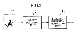
- the present invention is accomplished by a security system comprising: an object detecting unit which emits light and/or a radio wave from a building to a predetermined area outside the building, receives a wave reflected from an object, and detects the object on the basis of the reflected wave. Furthermore, a building intrusion predicting unit for tracking the object in the predetermined area on the basis of output of the detecting unit to predict whether or not the object will intrude into the building can be provided.
- the present invention is accomplished by a security system comprising: an object detecting unit which emits light and/or a radio wave from a building to a predetermined area outside the building, receives a wave reflected from an object, and detects the object on the basis of the reflected wave. Furthermore, a building intrusion predicting unit for tracking the object in the predetermined area on the basis of output of the detecting unit to predict whether or not the object will intrude into the building can be provided; wherein said object detecting unit has object detecting devices installed on a wall surface of the building so as to cover the predetermined area which is within a range of 360°.
- a security system monitors an object in an area within a predetermined range around a building, and relates to a method in which object detecting devices 1 are installed on the building and thereby a judgment is made as to whether or not a detected object will intrude into the area.
- Fig. 2 illustrates the configuration.
- the configuration comprises an object detecting unit 2 for detecting an object, and an area intrusion judging unit 3 for judging whether or not the detected object will intrude into the predetermined area.
- the invention will be described using a radar device as an object detecting device 1 capable of calculating relative velocity to the object and its position.
- the radar device comprises a transmitting unit 250 which modulates a radar wave and transmits the modulated radar wave; a receiving unit 255 which receives the reflected radar wave and generates data; an antenna unit 260; and a signal processing unit 24.
- the antenna unit 260 comprises a transmitting antenna 16 and receiving antennas 17(a), 17(b).
- a high-frequency signal in a millimeter wave band which has been transmitted from a transmitter 18 on a transmission frequency based on a modulated signal coming from a modulator 19, is emitted from the transmitting antenna 16.
- a radio wave signal reflected by a reflecting object such as a car and/or an object along a road is received by the receiving antennas 17(a) and 17(b). Then, the radio wave signal is frequency-converted by a mixer circuit 20. This mixer circuit 20 is also supplied with a signal from the transmitter 18. A low frequency signal which is generated by mixing these two signals is outputted to an analog circuit 21. A signal, which is outputted by the analog circuit 21 after amplification, is converted into a digital signal by an A/D converter 22. Then, the A/D converter 22 supplies the converted signal to an FFT processing unit 23.
- the FFT processing unit 23 measures a frequency spectrum of a signal as amplitude and phase information by means of fast Fourier transform, and then transmits the information to the signal processing unit 24. Using data in the frequency domain obtained in the FFT processing unit 23, the signal processing unit 24 calculates a range and relative velocity, and then outputs them as measurements of the range and the relative velocity.
- a double-channel CW (Continuous Wave) method will be described with reference to Figs. 3 and 4.
- Doppler shift is utilized to measure relative velocity of an object. Switching between two frequencies enables measurement of a distance to the object on the basis of phase information of a signal received at each frequency.
- a modulated signal is inputted to the transmitter 18.
- two frequencies f 1 and f 2 are transmitted while the frequencies are switched periodically.
- a radio wave which has been transmitted from the transmitting antenna 16 is reflected by an object in front. After that, the reflected signal is received by the receiving antennas 17(a) and 17(b).
- the mixer circuit 20 multiplies the received signal by the signal of the transmitter 18 to obtain beat signal thereof.
- a beat signal which is outputted from the mixer circuit 20 is so-called Doppler frequency.
- the Doppler frequency is calculated by the following equation.
- f d 2 • f c c R where f c is a carrier-wave frequency, R ⁇ is relative velocity, and c is light velocity.
- the analog circuit 21 separates and demodulates the received signal at each transmission frequency. Then, an A/D converter 22 performs analog-to-digital conversion of the received signal at each transmission frequency.
- Fig. 5 illustrates a received power pattern of each receiving antenna with respect to azimuth. Received power of each of the receiving antennas 17 (a) and 17(b) becomes highest when ⁇ is in a 0-degree direction. Therefore, for the signals inputted to the receiving antennas 17(a) and 17(b), a pattern of a sum signal (Sum pattern) and a pattern of a difference signal (Diff pattern) are constant as shown in Fig. 5.
- a range from a building to the area where intrusion is to be prohibited is Lw.
- a height (from the ground) of the position where the radar device is to be installed is Lh.
- Fig. 1B is a view which is viewed from the top of the building at this time.
- An area within the range of a distance Lw from the building is defined as an intrusion prohibited area 5.
- the radar device 1 is installed on the building; and as shown in Fig.
- a radio wave is transmitted to an area to be emitted 6 at which a range from the building is Lw.
- Figs. 1A to 1C are diagrams illustrating an example in which six radar devices, each of which has an antenna with a beam angle of 60°, are installed on the circumference of the building.
- the radar device 1 calculates the relative velocity, range, and azimuth of the object.
- a process flow of the area intrusion judging unit 3 is illustrated in Fig. 6.
- a sign of relative velocity of the object detected by the object detecting unit 2 is negative, it is judged that this object is approaching the building.
- the area intrusion judging unit 3 judges that the object has intruded into the area.
- the sign of the relative velocity of the object detected by the radar device is positive with respect to a direction in which the radar device emits a radio wave.
- the area intrusion judging unit 3 judges that this object is moving away from the building.
- the area intrusion judging unit 3 judges that the object has not intruded into the area.
- the invention shows a method for placing the object detecting device 1 and the configuration of the object detecting device 1 and will be described using a radar device as the object detecting device 1 capable of calculating the relative velocity to the object and its position.
- Fig. 7A illustrates a method in which the radar devices are installed in a multidirectional manner so as to cover 360°. According to this method, because the plurality of radar devices are installed in a multidirectional manner, one pole structure can cover 360° around the building as a detection area. A position and an emitting angle ⁇ p of each radar device can be calculated using the means similar to that of the first embodiment.
- Fig. 7B illustrates the emission area 6 of a radio wave, which is viewed from the top of the building; in this figure, six wide-angle antennas, each of which has a beam angle of 60°, are used. when an object intrudes into the emission area 6 shown in Fig. 7B, the radar devices can detect the relative velocity, intrusion position, and/or velocity of the object relative to the position of the building.
- Fig. 7C is a diagram illustrating an example of the configuration of the radar devices used at this time.
- the invention can be based on the assumption that a security system capable of the following is used:
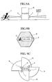
- Fig. 9A illustrates an example in which the radar device is installed on the side surface of.the building and a radio wave is emitted in parallel with the ground.
- Fig. 9B it is possible to cover all of the intrusion prohibited areas around the building as an emission area.
- an installing method to be applied when using four wide-angle antennas, each of which has a beam angle of at least 90°, includes a configuration as shown in Fig. 9C.
- a process flow in the building intrusion predicting unit 11 is shown in Fig. 10, and processing thereof will be described with reference to Fig. 11.
- the point P (t + ⁇ t) calculated by the above-mentioned step is represented by coordinates in the coordinate system x-y relative to the radar device 12.
- a coordinate system X-Y is defined.
- the radar device 12 is installed at its center, a horizontal direction of the building is X, and a vertical direction of the building is Y.
- a step 30 if ⁇ Dx or ⁇ Dy, which has been calculated in the step 29, is positive, the process proceeds to a step 31, and the building intrusion predicting unit 11 judges that this object is approaching the building.
- a step 32 if Dx(t + ⁇ t) or Dy(t + ⁇ t), which has been calculated in the step 28, is smaller than a predetermined value D, then the process proceeds to a step 33 where the building intrusion predicting unit 11 predicts that the object will intrude into the building.
- step 30 if Dx or Dy, which has been calculated in the step 29, is negative, the process proceeds to a step 34 where the building intrusion predicting unit 11 judges that this object is moving away from the building, resulting in prediction that the object will not intrude into the building.
- the present invention it is possible to detect an object before the object intrudes into a building.
- the object can be detected even in bad weather such as rain, fog, and/or snow. Accordingly, security is improved.
- a wide-angle antenna having a large emitting angle is used, the number of sensors can be reduced. Further, the antennas are installed on the building, which results in decrease in wiring and costs (easy installation is available).
- a radio wave is utilized, it is not necessary to adjust an optical axis, which improves efficiency in installation (easy installation is available).
- a plurality of object detecting devices are installed in a multidirectional manner so as to cover a predetermined area which is within a range of 360°, it is possible to reduce the number of locations where the object detecting devices are installed (easy installation is available).
- the detected object is tracked. Accordingly, it is possible to determine a path of the object before the object intrudes into a building, which improves security.
- the object detecting units are installed on a wall surface of the building, it is possible to detect intrusion of the object without marring outward appearance.
Landscapes
- Engineering & Computer Science (AREA)
- Radar, Positioning & Navigation (AREA)
- Remote Sensing (AREA)
- Computer Networks & Wireless Communication (AREA)
- Physics & Mathematics (AREA)
- General Physics & Mathematics (AREA)
- Radar Systems Or Details Thereof (AREA)
- Burglar Alarm Systems (AREA)
- Alarm Systems (AREA)
Applications Claiming Priority (2)
| Application Number | Priority Date | Filing Date | Title |
|---|---|---|---|
| JP2001385383 | 2001-12-19 | ||
| JP2001385383A JP2003187342A (ja) | 2001-12-19 | 2001-12-19 | セキュリティシステム |
Publications (2)
| Publication Number | Publication Date |
|---|---|
| EP1326090A2 true EP1326090A2 (fr) | 2003-07-09 |
| EP1326090A3 EP1326090A3 (fr) | 2004-01-07 |
Family
ID=19187843
Family Applications (1)
| Application Number | Title | Priority Date | Filing Date |
|---|---|---|---|
| EP02018291A Withdrawn EP1326090A3 (fr) | 2001-12-19 | 2002-08-23 | Système de securité |
Country Status (3)
| Country | Link |
|---|---|
| US (1) | US7084761B2 (fr) |
| EP (1) | EP1326090A3 (fr) |
| JP (1) | JP2003187342A (fr) |
Families Citing this family (33)
| Publication number | Priority date | Publication date | Assignee | Title |
|---|---|---|---|---|
| JP4086298B2 (ja) * | 2003-06-17 | 2008-05-14 | アルパイン株式会社 | 物体検出方法及び装置 |
| WO2005104417A2 (fr) * | 2004-01-20 | 2005-11-03 | Bae Systems Information & Electronic Systems Integration Inc. | Detection de mouvement et determination de distance multifrequence a travers des parois a l'aide d'une technique d'estimation basee sur la difference |
| US7460052B2 (en) * | 2004-01-20 | 2008-12-02 | Bae Systems Information And Electronic Systems Integration Inc. | Multiple frequency through-the-wall motion detection and ranging using a difference-based estimation technique |
| JP2005324297A (ja) * | 2004-05-17 | 2005-11-24 | Matsushita Electric Ind Co Ltd | ロボット |
| US7440620B1 (en) * | 2004-05-21 | 2008-10-21 | Rockwell Automation B.V. | Infrared safety systems and methods |
| JP2006329912A (ja) * | 2005-05-30 | 2006-12-07 | Hitachi Ltd | 物体検知センサ |
| JP3903221B2 (ja) * | 2005-06-24 | 2007-04-11 | オプテックス株式会社 | 防犯センサ |
| DE102005034048A1 (de) * | 2005-07-21 | 2007-01-25 | Robert Bosch Gmbh | Bewegungsmelder |
| JP4754292B2 (ja) * | 2005-07-25 | 2011-08-24 | セコム株式会社 | レーダ装置 |
| JP3909370B2 (ja) * | 2005-08-04 | 2007-04-25 | オプテックス株式会社 | 防犯センサ |
| JP4799173B2 (ja) * | 2005-12-27 | 2011-10-26 | 株式会社ユピテル | セキュリティ装置 |
| US8248473B2 (en) * | 2006-10-05 | 2012-08-21 | Graber Curtis E | Robotic sentry with low dispersion acoustic projector |
| JP2009103565A (ja) * | 2007-10-23 | 2009-05-14 | Omron Corp | 測定装置および方法 |
| JP5076070B2 (ja) * | 2007-10-26 | 2012-11-21 | オプテックス株式会社 | 対象検出装置、対象検出方法、および対象検出プログラム |
| US8169356B2 (en) * | 2007-12-31 | 2012-05-01 | Honeywell International Inc. | Anti-mask motion sensor |
| JP5018617B2 (ja) * | 2008-04-24 | 2012-09-05 | 積水ハウス株式会社 | 不審者検知装置、不審者検知方法、不審者検知装置付き住宅 |
| US7978069B2 (en) * | 2008-08-27 | 2011-07-12 | Honeywell International Inc. | Reliable security system by triangulation |
| US8159344B2 (en) * | 2008-10-28 | 2012-04-17 | Honeywell International, Inc. | Microwave motion detectors utilizing multi-frequency ranging and target angle detection |
| US9526156B2 (en) * | 2010-05-18 | 2016-12-20 | Disney Enterprises, Inc. | System and method for theatrical followspot control interface |
| US9365126B2 (en) * | 2013-05-10 | 2016-06-14 | Qualcomm Incorporated | System and method for detecting the presence of a moving object below a vehicle |
| US10060234B2 (en) * | 2015-07-20 | 2018-08-28 | Halliburton Energy Services, Inc. | Low-debris low-interference well perforator |
| EP3261071B1 (fr) | 2016-06-22 | 2020-04-01 | Outsight | Procédé et système de detection d'intrusions d'un volume sous surveillance |
| FR3054042B1 (fr) * | 2016-07-12 | 2018-08-17 | Rockwell Collins France | Procede et dispositif de determination d'une zone geographique operationnelle observee par un capteur |
| WO2018081328A1 (fr) * | 2016-10-26 | 2018-05-03 | Ring Inc. | Zones d'intrusion personnalisables pour dispositifs d'enregistrement et de communication audio/vidéo |
| US12096156B2 (en) | 2016-10-26 | 2024-09-17 | Amazon Technologies, Inc. | Customizable intrusion zones associated with security systems |
| KR101876797B1 (ko) * | 2016-11-28 | 2018-07-11 | 주식회사 아이유플러스 | 울타리 경계용 레이더의 침입자 타겟 검출 방법 및 장치 |
| RU2690216C1 (ru) * | 2018-04-18 | 2019-05-31 | Федеральное государственное казенное образовательное учреждение высшего образования "Калининградский пограничный институт Федеральной службы безопасности Российской Федерации" | Способ охранного мониторинга дороги линейным радиоволновым средством обнаружения |
| US10438464B1 (en) | 2018-06-06 | 2019-10-08 | Ademco Inc. | Systems and methods for determining and verifying a presence of an object or an intruder in a secured area |
| US10996325B2 (en) | 2018-11-30 | 2021-05-04 | Ademco Inc. | Systems and methods for adjusting a signal broadcast pattern of an intrusion detector |
| US11074794B2 (en) | 2018-11-30 | 2021-07-27 | Ademco Inc. | Systems and methods for activating and deactivating controlled devices in a secured area |
| US10762773B1 (en) | 2019-08-19 | 2020-09-01 | Ademco Inc. | Systems and methods for building and using a false alarm predicting model to determine whether to alert a user and/or relevant authorities about an alarm signal from a security system |
| WO2022063665A1 (fr) * | 2020-09-22 | 2022-03-31 | Signify Holding B.V. | Transmission d'alerte de sécurité indiquant une position dans le bâtiment d'un destinataire |
| CN117671906B (zh) * | 2024-01-15 | 2025-01-28 | 广东耀邦新能源股份有限公司 | 一种仿真监控装置的控制方法、装置、设备以及存储介质 |
Family Cites Families (13)
| Publication number | Priority date | Publication date | Assignee | Title |
|---|---|---|---|---|
| DE2656399C3 (de) * | 1976-12-13 | 1979-10-11 | Siemens Ag, 1000 Berlin Und 8000 Muenchen | Schaltungsanordnung für ein Einbruchalarmgerät mit Koinzidenzbetrieb eines Ultraschall- und eines elektromagnetischen Dopplergerätes |
| US4470696A (en) * | 1981-10-14 | 1984-09-11 | Systems Research Laboratories, Inc. | Laser doppler velocimeter |
| WO1993023833A1 (fr) | 1992-05-11 | 1993-11-25 | Saab-Scania Combitech Aktiebolag | Dispositif de detection et de transfert d'information |
| JPH0721475A (ja) | 1993-06-30 | 1995-01-24 | Fuji Electric Co Ltd | 侵入物体監視装置 |
| JP2978416B2 (ja) * | 1995-03-08 | 1999-11-15 | 智彦 鈴木 | 警報装置 |
| US5936524A (en) * | 1996-05-02 | 1999-08-10 | Visonic Ltd. | Intrusion detector |
| US5910767A (en) * | 1997-07-11 | 1999-06-08 | Laser Guard | Intruder detector system |
| JP2000003478A (ja) | 1998-06-16 | 2000-01-07 | Mitsubishi Electric Corp | 動態検知装置 |
| US6208248B1 (en) * | 1999-01-28 | 2001-03-27 | Anro Engineering, Inc. | Quick response perimeter intrusion detection sensor |
| US6307475B1 (en) * | 1999-02-26 | 2001-10-23 | Eric D. Kelley | Location method and system for detecting movement within a building |
| JP4404990B2 (ja) | 1999-05-26 | 2010-01-27 | 三井・デュポンポリケミカル株式会社 | 溶融袋 |
| JP2000338231A (ja) | 1999-05-31 | 2000-12-08 | Mitsubishi Electric Corp | 侵入者検知装置 |
| EP1067397B1 (fr) * | 1999-07-03 | 2006-01-25 | Siemens Schweiz AG | Détecteur de mouvement à effet Doppler |
-
2001
- 2001-12-19 JP JP2001385383A patent/JP2003187342A/ja active Pending
-
2002
- 2002-08-23 US US10/226,116 patent/US7084761B2/en not_active Expired - Fee Related
- 2002-08-23 EP EP02018291A patent/EP1326090A3/fr not_active Withdrawn
Also Published As
| Publication number | Publication date |
|---|---|
| US20030112142A1 (en) | 2003-06-19 |
| EP1326090A3 (fr) | 2004-01-07 |
| JP2003187342A (ja) | 2003-07-04 |
| US7084761B2 (en) | 2006-08-01 |
Similar Documents
| Publication | Publication Date | Title |
|---|---|---|
| EP1326090A2 (fr) | Système de securité | |
| US7463182B1 (en) | Radar apparatus | |
| CA2451916C (fr) | Systeme et procede de detection d'objets | |
| EP1441318B1 (fr) | Système de sécurité | |
| EP1371997B1 (fr) | D tection d'objet stationnaire sur route au moyen d'un radar | |
| EP1031851B1 (fr) | Appareil radar | |
| EP1548458A2 (fr) | Radar monté dans un véhicule | |
| AU2002325370A1 (en) | Passive moving object detection system and method using signals transmitted by a mobile telephone station | |
| US20030222809A1 (en) | Millimeter wave radar monitoring system | |
| US20030001771A1 (en) | Still object detecting method of scanning radar | |
| JP6957820B2 (ja) | 電波センサ、調整方法および調整プログラム | |
| JP2001042034A (ja) | レーダ装置 | |
| US20060267764A1 (en) | Object detection sensor | |
| WO2013175558A1 (fr) | Dispositif de radar et procédé de vérification d'angle | |
| EP3690484B1 (fr) | Dispositif radar et procédé de détection de cible | |
| JP7257369B2 (ja) | 電子機器、電子機器の制御方法、及びプログラム | |
| US20100238066A1 (en) | Method and system for generating a target alert | |
| EP3865909B1 (fr) | Dispositif électronique, procédé de commande de dispositif électronique et programme de commande de dispositif électronique | |
| JPH11118917A (ja) | Fm−cwレーダ装置 | |
| JP3230362B2 (ja) | 障害物検知装置 | |
| JP3853642B2 (ja) | 自動車用レーダ装置 | |
| JP2001084485A (ja) | 車両検出装置 | |
| JP2000111644A (ja) | 車両検出装置 | |
| JP3369501B2 (ja) | 電波式道路情報検出装置 | |
| JP7622479B2 (ja) | レーダ装置とその制御方法 |
Legal Events
| Date | Code | Title | Description |
|---|---|---|---|
| PUAI | Public reference made under article 153(3) epc to a published international application that has entered the european phase |
Free format text: ORIGINAL CODE: 0009012 |
|
| AK | Designated contracting states |
Designated state(s): AT BE BG CH CY CZ DE DK EE ES FI FR GB GR IE IT LI LU MC NL PT SE SK TR |
|
| AX | Request for extension of the european patent |
Extension state: AL LT LV MK RO SI |
|
| RIN1 | Information on inventor provided before grant (corrected) |
Inventor name: TSUBOTA, MIKITO Inventor name: KONDOH, HIROSHI Inventor name: SASAKI, MITSUHIDE Inventor name: TAKANO, KAZUAKI Inventor name: MIZUISHI, KENICHI Inventor name: NAKAZAWA, TERUMI Inventor name: SATO, KAZUHIKO Inventor name: KURAGAKI, SATORU Inventor name: KURODA, HIROSHI Inventor name: IZUMI, SHIHO |
|
| PUAL | Search report despatched |
Free format text: ORIGINAL CODE: 0009013 |
|
| RIN1 | Information on inventor provided before grant (corrected) |
Inventor name: TSUBOTA, MIKITO Inventor name: KONDOH, HIROSHI Inventor name: SASAKI, MITSUHIDE Inventor name: TAKANO, KAZUAKI Inventor name: MIZUISHI, KENICHI Inventor name: NAKAZAWA, TERUMI Inventor name: SATO, KAZUHIKO Inventor name: KURAGAKI, SATORU Inventor name: KURODA, HIROSHI Inventor name: IZUMI, SHIHO |
|
| AK | Designated contracting states |
Kind code of ref document: A3 Designated state(s): AT BE BG CH CY CZ DE DK EE ES FI FR GB GR IE IT LI LU MC NL PT SE SK TR |
|
| AX | Request for extension of the european patent |
Extension state: AL LT LV MK RO SI |
|
| 17P | Request for examination filed |
Effective date: 20040428 |
|
| AKX | Designation fees paid |
Designated state(s): DE FR GB IT |
|
| 17Q | First examination report despatched |
Effective date: 20041112 |
|
| STAA | Information on the status of an ep patent application or granted ep patent |
Free format text: STATUS: THE APPLICATION IS DEEMED TO BE WITHDRAWN |
|
| 18D | Application deemed to be withdrawn |
Effective date: 20090303 |