EP1329234A2 - Sicherheitsanordnung für Spritze vorgefüllt mit flüssigem Arzneimittel - Google Patents
Sicherheitsanordnung für Spritze vorgefüllt mit flüssigem Arzneimittel Download PDFInfo
- Publication number
- EP1329234A2 EP1329234A2 EP03290416A EP03290416A EP1329234A2 EP 1329234 A2 EP1329234 A2 EP 1329234A2 EP 03290416 A EP03290416 A EP 03290416A EP 03290416 A EP03290416 A EP 03290416A EP 1329234 A2 EP1329234 A2 EP 1329234A2
- Authority
- EP
- European Patent Office
- Prior art keywords
- cap
- syringe
- sheath
- needle
- tube
- Prior art date
- Legal status (The legal status is an assumption and is not a legal conclusion. Google has not performed a legal analysis and makes no representation as to the accuracy of the status listed.)
- Granted
Links
Images


Classifications
-
- A—HUMAN NECESSITIES
- A61—MEDICAL OR VETERINARY SCIENCE; HYGIENE
- A61M—DEVICES FOR INTRODUCING MEDIA INTO, OR ONTO, THE BODY; DEVICES FOR TRANSDUCING BODY MEDIA OR FOR TAKING MEDIA FROM THE BODY; DEVICES FOR PRODUCING OR ENDING SLEEP OR STUPOR
- A61M5/00—Devices for bringing media into the body in a subcutaneous, intra-vascular or intramuscular way; Accessories therefor, e.g. filling or cleaning devices, arm-rests
- A61M5/178—Syringes
- A61M5/31—Details
- A61M5/32—Needles; Details of needles pertaining to their connection with syringe or hub; Accessories for bringing the needle into, or holding the needle on, the body; Devices for protection of needles
- A61M5/3205—Apparatus for removing or disposing of used needles or syringes, e.g. containers; Means for protection against accidental injuries from used needles
- A61M5/321—Means for protection against accidental injuries by used needles
- A61M5/3243—Means for protection against accidental injuries by used needles being axially-extensible, e.g. protective sleeves coaxially slidable on the syringe barrel
- A61M5/326—Fully automatic sleeve extension, i.e. in which triggering of the sleeve does not require a deliberate action by the user
-
- A—HUMAN NECESSITIES
- A61—MEDICAL OR VETERINARY SCIENCE; HYGIENE
- A61M—DEVICES FOR INTRODUCING MEDIA INTO, OR ONTO, THE BODY; DEVICES FOR TRANSDUCING BODY MEDIA OR FOR TAKING MEDIA FROM THE BODY; DEVICES FOR PRODUCING OR ENDING SLEEP OR STUPOR
- A61M5/00—Devices for bringing media into the body in a subcutaneous, intra-vascular or intramuscular way; Accessories therefor, e.g. filling or cleaning devices, arm-rests
- A61M5/178—Syringes
- A61M5/31—Details
- A61M5/32—Needles; Details of needles pertaining to their connection with syringe or hub; Accessories for bringing the needle into, or holding the needle on, the body; Devices for protection of needles
- A61M5/3205—Apparatus for removing or disposing of used needles or syringes, e.g. containers; Means for protection against accidental injuries from used needles
- A61M5/321—Means for protection against accidental injuries by used needles
- A61M5/3243—Means for protection against accidental injuries by used needles being axially-extensible, e.g. protective sleeves coaxially slidable on the syringe barrel
- A61M5/326—Fully automatic sleeve extension, i.e. in which triggering of the sleeve does not require a deliberate action by the user
- A61M2005/3261—Fully automatic sleeve extension, i.e. in which triggering of the sleeve does not require a deliberate action by the user triggered by radial deflection of the anchoring parts between sleeve and syringe barrel, e.g. spreading of sleeve retaining hooks having slanted surfaces by engagement with conically shaped collet of the piston rod during the last portion of the injection stroke of the plunger
-
- A—HUMAN NECESSITIES
- A61—MEDICAL OR VETERINARY SCIENCE; HYGIENE
- A61M—DEVICES FOR INTRODUCING MEDIA INTO, OR ONTO, THE BODY; DEVICES FOR TRANSDUCING BODY MEDIA OR FOR TAKING MEDIA FROM THE BODY; DEVICES FOR PRODUCING OR ENDING SLEEP OR STUPOR
- A61M5/00—Devices for bringing media into the body in a subcutaneous, intra-vascular or intramuscular way; Accessories therefor, e.g. filling or cleaning devices, arm-rests
- A61M5/178—Syringes
- A61M5/31—Details
- A61M5/32—Needles; Details of needles pertaining to their connection with syringe or hub; Accessories for bringing the needle into, or holding the needle on, the body; Devices for protection of needles
- A61M5/3205—Apparatus for removing or disposing of used needles or syringes, e.g. containers; Means for protection against accidental injuries from used needles
- A61M5/321—Means for protection against accidental injuries by used needles
- A61M5/3243—Means for protection against accidental injuries by used needles being axially-extensible, e.g. protective sleeves coaxially slidable on the syringe barrel
- A61M5/326—Fully automatic sleeve extension, i.e. in which triggering of the sleeve does not require a deliberate action by the user
- A61M2005/3261—Fully automatic sleeve extension, i.e. in which triggering of the sleeve does not require a deliberate action by the user triggered by radial deflection of the anchoring parts between sleeve and syringe barrel, e.g. spreading of sleeve retaining hooks having slanted surfaces by engagement with conically shaped collet of the piston rod during the last portion of the injection stroke of the plunger
- A61M2005/3264—Trigger provided at the proximal end, i.e. syringe end opposite to needle mounting end
Definitions
- the present invention relates to a safety assembly for a pre-filled syringe injection of liquid, in particular a drug.
- the syringe plunger has an operating end external to the body of the syringe and one end internal to the body of this syringe carrying A piston.
- the operating end of the pusher is also called the pusher head.
- Certain medical products such as vaccines, heparins and their derivatives and others drugs with precise dosages, cannot be stored in containers or syringes plastic as a result of moisture uptake which could compromise its composition.
- the problem is therefore to adapt a safety mechanism on syringes of preferably in glass, in particular 0.1 to 2 ml capacity, any type of internal mechanism these syringes being excluded.
- the object of the invention is to remedy the drawbacks set out above, while meeting the following criteria: small footprint, adaptation at the end of the front chain packaging, safety with one-hand activation, automatic, independently controlled of human will, protection closest to the 100% desired.
- the return means comprise a spring thrust intended to come to bear on an internal support shoulder formed in the sheath, which comprises for example an internal housing of revolution in which is arranged the thrust spring.
- This internal housing is, for example, delimited by the internal support shoulder of the thrust spring.
- the security assembly may include means for blocking the flange of the body syringe after relaxation of the return means.
- the sheath and the cap comprise means complementary immobilization in rotation of one relative to the other.
- the sheath can carry external gripping means intended to be gripped by a user's fingers to inject the liquid by axial approximation of a operating end of the pusher and gripping means.
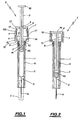
- FIG. 1 to 3 a safety assembly for a syringe conventional liquid injection S, in particular a medical liquid, according to a first mode of realization of the invention.
- This safety assembly is designated by the general reference E.
- the syringe S is pre-filled, ready to use, and has a tubular body K, forming a reservoir for the liquid, carrying a needle A for injecting the liquid, and a pusher P mounted movable in the body K between a waiting position, such as shown in Figure 1, and a liquid injection end position, as shown in figure 2.
- the pusher P has a first end PE, external to the body K, and a second end PI, internal to the body K, carrying a conventional piston PO.
- the outer end PE forms an operating end of the pusher.
- the assembly E comprises a tubular safety sheath in which the syringe, in particular the body K.
- the sheath of revolution, is constituted for example by a cylindrical tube 1 made of plastic or any other material having transparency sufficient to allow viewing of the liquid contained in the body K of the syringe as well as a possible drug identification label. Note that the tube cylindrical 1 is stepped.
- the body K can be moved axially in the tube 1 between an active position in which needle A protrudes through a distal (upper) end of tube 1, and a protective position in which the needle A is retracted into the tube 1.
- the position active is shown in Figures 1 and 2.
- the protective position is shown in the figure 3.
- the body K of the syringe has a distal end carrying the needle A and a proximal end provided with a CL flange.
- the internal surface of the tube 1 has three raised guides 2 arranged in the direction longitudinal of this tube 1, spaced apart by 120 °, intended to center the body K of the syringe, reduce the clearance and improve the sliding of the body K in the tube 1, while allowing the passage of a classic rubber cap C (shown in phantom) in Figure 1) protecting needle A before using the syringe.
- the proximal end of the tube 1 carries, from bottom to top, a first internal housing of revolution 3 extended by a second internal revolution housing 4 with a diameter greater than that of the first internal housing.
- the body K is immobilized relative to the tube 1 by means of blocking means comprising, on the one hand, a seat 4E for supporting the collar CL formed by a shoulder internal delimiting the second housing 4, and on the other hand, retractable means of tightening of the collar CL against this seat 4E, carried by the proximal end of the tube 1.
- blocking means comprising, on the one hand, a seat 4E for supporting the collar CL formed by a shoulder internal delimiting the second housing 4, and on the other hand, retractable means of tightening of the collar CL against this seat 4E, carried by the proximal end of the tube 1.
- the retractable clamping means are formed by two legs 5, substantially diametrically opposite, partially cut out in the wall of the tube 1 delimiting the second housing 4.
- the tabs 5 are terminated by retractable lugs 6 intended to hold the collar CL of the body of the syringe in support against seat 4E.
- the legs 5 are folded so as to extend substantially in a diametral longitudinal plane of the tube.
- the clamping means retractable could have only one leg 5.
- the body K of the syringe is resiliently returned to its protective position by a thrust spring R disposed in the first housing 3.
- This spring R is in support, on the one hand, on an internal shoulder 3E, delimiting the first internal housing 3, and on the other hand hand, on the collar CL of the body K of the syringe.
- the internal support shoulder 3E is disposed between the support seat 4E of the collar CL and the distal end of the tube 1.
- FIG. 1 which represents the safety assembly and the syringe ready to be used, the spring R is compressed. This spring remains in this state until the end of the injection of the liquid.
- the pins 6 therefore make it possible to immobilize the body K relative to the tube 1 in position active by opposing the elastic return force of the spring R.
- proximal end of the second internal housing 4 is delimited by a inner ring 7 molded with the tube 1.
- the means for blocking the body K of the syringe relative to the tube 1 are releasable using means activated when the pusher P is in the end of injection position.
- the means for releasing the means of locking include a cap of revolution 8, preferably made of plastic, slidably mounted axially in the second housing 4 of the tube 1, between a high position standby, as shown in FIG. 1, and a retracting position of the lugs 6, as shown in Figure 2.
- the cap 8 is crossed by the pusher P which extends through a hole 9 made in the proximal end of this cap 8.
- the cap 8 also includes internal lugs 10 spaced apart by 90 °, and an outer ring 11 molded with the distal end of this cap.
- the inner ring 7 of the second housing 4 and the outer ring 11 of the cap .8 delimit complementary annular shoulders, forming stops, limiting the stroke of this cap 8, after release of the means for blocking the body K, by opposing the elastic spring return force R (see Figure 3).
- Complementary rings 7, 11 therefore act as a return limiter for the cap 8.
- the tube 1 and the cap 8 include complementary means for immobilizing the rotation of one relative to the other.
- These complementary means of immobilization in rotation include, by example, at least one longitudinal groove 13, formed in the cap 8, cooperating by fitting with a corresponding finger 13A radially extending the inner ring 7 of the second housing 4.
- the cap has two grooves 13 diametrically opposite as shown in Figures 1 to 3.
- the body K of the syringe is filled with liquid to be injected. This liquid is retained in the body K by the piston PO.
- the pusher P is separated from this piston.
- the body K of the pre-filled syringe is placed in the tube 1 by snapping on the flange CL under the lugs 6 after having compressed the spring R in the first housing 3.
- the cap 8 is engaged in the second housing 4, being for example pressed into this second housing 4 until the outer ring 11 comes into contact lugs 6, as shown in FIG. 1.
- the plunger P of the syringe is connected to the piston PO by introducing the end distal of this pusher in the cap 8 and the tube 1, through the orifice 9 of this cap 8.
- the safety assembly E is then ready for use in the configuration illustrated on the Figure 1, needle A of the syringe projecting through the distal end of tube 1.
- the gripping at the level of the tube 1 is carried out using gripping means external, carried by the tube 1, intended to be grasped by the fingers of a user for inject the liquid by axial approximation of the external end PE of the pusher and the gripping means.
- the means for gripping the tube 1 comprise a shoulder 1E formed on the external surface of the tube 1.
- the user grasps the assembly E between the index and the major.
- the thumb exerts pressure from the syringe on the external end PE of the plunger.
- the index and middle fingers hold the tube 1 by grasping the gripping shoulder 1E.
- the user pushes the PE plunger into the body of the syringe while bringing the axially the PE end of the pusher of the gripping shoulder 1E, this up to reach the end of injection position shown in Figure 2.
- the displacement stroke of the pusher P from its standby position to its injection end position includes a final stroke for securing this pusher P to cap B preceded by an initial dead stroke of the pusher P relative to the cap 8 during which this cap 8 remains stationary.
- the external end PE of the pusher forming a head securing, cooperates with a counterbore delimiting the edge of the orifice 9 of the cap.
- FIG. 2 it can be seen that the body K of the syringe is emptied of its contained, the liquid having been injected into the body of a patient by the user.
- the push-button P is at the end of the race.
- the spring R relaxes and pushes the empty syringe upwards (considering the figures) so as to snap the collar CL of the body between the edge of the orifice 9 of the cap and the pins 10 as is shown in Figure 3.
- the cap 8 also moves under the effect of the force of return of the spring R to the position shown in FIG. 3 in which the rings 7, 11 cooperate with each other to limit the stroke of the cap 8 and therefore the retraction stroke syringe.
- the needle A is retracted in the tube 1 thereby achieving 100% security.
- the tube 1 does not have the second internal housing of the first mode of achievement.
- the gripping means of the tube 1 are constituted by two fins or ears 15, substantially transverse to the axis of the tube, diametrically opposite, extended in the longitudinal direction (parallel to the axis of the tube 1) by two legs 16 terminated by inverted pins 17, 18.
- the ears 15 are preferably from molding with tube 1.
- pivots 19 protrude from the external surface of the proximal end of tube 1.
- the pivots 19 materialize a geometric axis substantially transverse to the tube 1.
- the two pivots 19 carry two identical arms 20, 21, generally in the shape of a very U open. These arms 20, 21 are reversed by their positioning at 180 °. Each arm 20, 21 has a pivot hole 22 for fitting onto the corresponding pivot 19. Each arm 20, 21 has short and long parts separated by the corresponding pivot 22. The short part is terminated by a bent end substantially at right angles, carrying a lug 23. The long part is also terminated by a bent end substantially at right angle, comprising an internal boss 24 (see Figures 5 and 6).
- bent ends of the short and long parts of the arms 20, 21 form, respectively, of the clamping ends of the collar CL against the seat 4E and of the operating ends of these arms 20, 21.
- the pins 23 When the syringe is placed in the tube 1, the pins 23 retain the flange CL of the syringe in the tube 1 while compressing the spring R in the housing 3.
- the arms 20, 21 are placed in a forced clamping position of the flange CL of the makes the positioning of their boss 24 below the gripping ears 15. This positioning is symmetrical due to the arrangement of the arms 20, 21 at 180 ° from one another (see figure 5).
- the user applies two fingers (in the index and middle fingers) on both the ears 15 and the arms 20, 21.
- the operating ends of the arms 20, 21, cooperate with the ears 15 so as to be moved, when the pusher reaches its end position injection, from the forced clamping position of the flange CL shown in FIG. 5, to a forced release position of this flange CL, shown in Figure 6.
- the passage from the forced clamping position to the forced release position of the flange made by crossing a hard point and elastic deformation of the arms 20, 21.
- the bosses 24 escape the ears 15, which separates the pins 23 from the flange CL and releases the spring R.
- syringes pre-filled with vaccine should be kept and transported at low temperature.
- the injection of certain vaccines is preceded of a "vein test" which consists in pricking the needle into the body of a patient, holding forcefully the syringe, and pull on the external end of the plunger so as to achieve an aspiration. If a fine trace of blood appears in the part of the syringe where is attached needle, injection should not be performed. User must prick patient again a few centimeters away from the previous bite. Under no circumstances should a vaccine be injected into the bloodstream.
- FIG. 8 to 13 there is shown a safety assembly E according to a third embodiment of the invention. This last embodiment allows in particular the use of a syringe containing a vaccine.
- FIGS. 8 to 13 elements similar to those of the preceding figures are designated by identical references.
- FIG. 8 to 10 we recognize the elements similar to those of the modes of previous embodiments, namely the tube 1 comprising the housing 3 in which the spring R.
- the proximal end of the tube 1 is extended by two lugs 33, 34 of preferably diametrically opposite.
- the number of pins 33, 34 can be less than or greater than two.
- the lugs 33, 34 constitute blocking means having a function for immobilizing the body K of the syringe relative to the tube by tightening the flange CL of this body between the lugs 33, 34 and the support seat 4E.
- the function of pins 33, 34 is therefore similar to those of pins 6 of the first embodiment of the invention.
- Two gripping fins 35, 36 similar to the ears 15 of the second mode of realization, came from molding with the proximal end of the tube 1 and arranged at 180 ° one from the other.
- the tube 1 is shown isolated from the assembly E in FIG. 11.
- the cap 8 (see in particular FIGS. 12 and 13) in this case comprises two longitudinal tabs 38, 39, substantially diametrically opposite, extending its distal end. The end proximal of the cap 8 is pierced with a hole 40.
- the cap 8 further comprises two vertical longitudinal slots 41, 42 offset by 90 ° relative to the tongues 38, 39.
- the lights 41, 42 cooperate by interlocking with the fins 15 so as to form complementary means for immobilizing the cap 8 in rotation relative to to tube 1.
- the lugs 33, 34 are retractable, so as to release the flange CL, by cooperation with ramps 43, 44 limiting the proximal ends of the lumens 41, 42.
- the hole 40 of the cap allows mounting of the pusher in the injection assembly.
- the pusher P is secured to the cap 8 using conventional means not shown.
- FIG. 8 represents the safety assembly E in a configuration ready for its use, the syringe needle protruding through the distal end of the tube 1. Leaving of this configuration, the user performs an injection, in particular intramuscularly or in subcutaneously, holding the tube 1 between the index and middle fingers, using the fins 15, while press with your thumb on the external end PE of the pusher.
- the cap 8 being secured at pusher P, this cap sinks under the effect of the thumb pressure in the same sense that the pusher P until reaching the position shown in Figure 9.
- FIG. 10 which illustrates the configuration of the safety assembly E after use, we see that the needle is retracted into the tube 1.
- the syringe and the needle are well self-retractable, the tube 1 constituting a stable part serving as a fixed support.
- the tube 1 by its fins 33, 36 provides stability on a surface not plane.
- the distal end of the tube 1 having a reduced diameter, for example 9 mm, which prevents accidental introduction of a user's finger.
- the safety of assembly E therefore reaches practically 100%, and, in accordance with the object of the invention, the triggering of security (retraction of the needle) is automatic and independent of human will.
- the retraction of the needle is carried out with one hand, without any special gesture, respecting the medical rules and the practices of nursing staff.
- the invention allows both caregivers and people who have to handle, convey or destroy used syringes, to avoid any risk of accidents.
Landscapes
- Health & Medical Sciences (AREA)
- Engineering & Computer Science (AREA)
- Life Sciences & Earth Sciences (AREA)
- Animal Behavior & Ethology (AREA)
- Anesthesiology (AREA)
- Biomedical Technology (AREA)
- Heart & Thoracic Surgery (AREA)
- Hematology (AREA)
- Environmental & Geological Engineering (AREA)
- Vascular Medicine (AREA)
- General Health & Medical Sciences (AREA)
- Public Health (AREA)
- Veterinary Medicine (AREA)
- Infusion, Injection, And Reservoir Apparatuses (AREA)
- Medical Preparation Storing Or Oral Administration Devices (AREA)
- Medicines Containing Material From Animals Or Micro-Organisms (AREA)
Priority Applications (1)
| Application Number | Priority Date | Filing Date | Title |
|---|---|---|---|
| EP07120297A EP1892004A3 (de) | 1998-12-08 | 1999-06-09 | Sicherheitsanordnung für Spritze vorgefüllt mit flüssigem Arzneimittel |
Applications Claiming Priority (3)
| Application Number | Priority Date | Filing Date | Title |
|---|---|---|---|
| FR9815628 | 1998-12-08 | ||
| FR9815628A FR2787335B1 (fr) | 1998-12-08 | 1998-12-08 | Securite pour seringues pre-remplies |
| EP99923709A EP1148904B9 (de) | 1998-12-08 | 1999-06-09 | Sicherheitsanordnung für spritze vorgefüllt mit flüssigem arzneimittel |
Related Parent Applications (1)
| Application Number | Title | Priority Date | Filing Date |
|---|---|---|---|
| EP99923709A Division EP1148904B9 (de) | 1998-12-08 | 1999-06-09 | Sicherheitsanordnung für spritze vorgefüllt mit flüssigem arzneimittel |
Related Child Applications (1)
| Application Number | Title | Priority Date | Filing Date |
|---|---|---|---|
| EP07120297A Division EP1892004A3 (de) | 1998-12-08 | 1999-06-09 | Sicherheitsanordnung für Spritze vorgefüllt mit flüssigem Arzneimittel |
Publications (3)
| Publication Number | Publication Date |
|---|---|
| EP1329234A2 true EP1329234A2 (de) | 2003-07-23 |
| EP1329234A3 EP1329234A3 (de) | 2003-08-20 |
| EP1329234B1 EP1329234B1 (de) | 2008-02-13 |
Family
ID=9533842
Family Applications (3)
| Application Number | Title | Priority Date | Filing Date |
|---|---|---|---|
| EP07120297A Withdrawn EP1892004A3 (de) | 1998-12-08 | 1999-06-09 | Sicherheitsanordnung für Spritze vorgefüllt mit flüssigem Arzneimittel |
| EP99923709A Expired - Lifetime EP1148904B9 (de) | 1998-12-08 | 1999-06-09 | Sicherheitsanordnung für spritze vorgefüllt mit flüssigem arzneimittel |
| EP03290416A Expired - Lifetime EP1329234B1 (de) | 1998-12-08 | 1999-06-09 | Sicherheitsanordnung für Spritze vorgefüllt mit flüssigem Arzneimittel |
Family Applications Before (2)
| Application Number | Title | Priority Date | Filing Date |
|---|---|---|---|
| EP07120297A Withdrawn EP1892004A3 (de) | 1998-12-08 | 1999-06-09 | Sicherheitsanordnung für Spritze vorgefüllt mit flüssigem Arzneimittel |
| EP99923709A Expired - Lifetime EP1148904B9 (de) | 1998-12-08 | 1999-06-09 | Sicherheitsanordnung für spritze vorgefüllt mit flüssigem arzneimittel |
Country Status (9)
| Country | Link |
|---|---|
| US (1) | US6872190B1 (de) |
| EP (3) | EP1892004A3 (de) |
| JP (1) | JP4125491B2 (de) |
| AT (2) | ATE385818T1 (de) |
| AU (1) | AU4048199A (de) |
| CA (1) | CA2361100A1 (de) |
| DE (2) | DE69923706T2 (de) |
| FR (1) | FR2787335B1 (de) |
| WO (1) | WO2000033900A1 (de) |
Cited By (6)
| Publication number | Priority date | Publication date | Assignee | Title |
|---|---|---|---|---|
| US7101351B2 (en) | 2003-11-03 | 2006-09-05 | Becton, Dickinson And Company | Safety device for a syringe |
| US7344517B2 (en) | 2004-01-20 | 2008-03-18 | Becton, Dickinson And Company | Syringe having a retractable needle |
| US7468054B2 (en) | 2003-11-03 | 2008-12-23 | Becton, Dickinson And Company | Safety shield system for a syringe |
| US7497847B2 (en) | 2003-11-03 | 2009-03-03 | Becton, Dickinson And Company | Safety shield system for a syringe |
| US7604613B2 (en) | 2004-01-20 | 2009-10-20 | Beckton, Dickinson And Company | Syringe having a retractable needle |
| US8062252B2 (en) | 2005-02-18 | 2011-11-22 | Becton, Dickinson And Company | Safety shield system for a syringe |
Families Citing this family (23)
| Publication number | Priority date | Publication date | Assignee | Title |
|---|---|---|---|---|
| FR2801795B1 (fr) | 1999-12-07 | 2002-07-05 | Plastef Investissements | Dispositif de support de securite pour une seringue et ensemble d'un tel dispositif et d'une seringue |
| GB0003790D0 (en) | 2000-02-18 | 2000-04-05 | Astrazeneca Uk Ltd | Medical device |
| US6613022B1 (en) | 2000-05-05 | 2003-09-02 | Safety Syringes, Inc. | Passive needle guard for syringes |
| AUPR657501A0 (en) * | 2001-07-26 | 2001-08-16 | Afra Design Pty Limited | Protective syringe |
| FR2830765B1 (fr) | 2001-10-15 | 2004-07-23 | Plastic Omnium Cie | Dispositif de securite pour une seringue |
| EP1359479A1 (de) * | 2002-05-02 | 2003-11-05 | Zenith International SA | Uhr mit springendem Sekundenzeiger |
| US7247151B2 (en) * | 2002-05-09 | 2007-07-24 | Adam Slawson | Injector with shielded needle |
| US8372044B2 (en) | 2005-05-20 | 2013-02-12 | Safety Syringes, Inc. | Syringe with needle guard injection device |
| US9076483B2 (en) * | 2005-10-11 | 2015-07-07 | Thomson Licensing Llc | DVD replications system and method |
| US7637889B2 (en) * | 2006-11-15 | 2009-12-29 | Glynntech, Inc. | Drug delivery device with sliding valve and methodology |
| US8382713B2 (en) * | 2006-12-11 | 2013-02-26 | Kenergy Scientific, Inc. | Drug delivery device and methodology |
| JP2009240411A (ja) * | 2008-03-28 | 2009-10-22 | Terumo Corp | 医薬品容器 |
| US7811261B2 (en) | 2008-06-02 | 2010-10-12 | Sta-Med, Llc | Needle cover assembly for a syringe |
| US8162882B2 (en) | 2010-06-23 | 2012-04-24 | Sta-Med, Llc | Automatic-locking safety needle covers and methods of use and manufacture |
| WO2012166746A1 (en) | 2011-05-31 | 2012-12-06 | Sta-Med, Llc | Blood collection safety devices and methods of use and manufacture |
| US9248242B2 (en) * | 2012-04-20 | 2016-02-02 | Safety Syringes, Inc. | Anti-needle stick safety device for injection device |
| USD765838S1 (en) | 2015-03-26 | 2016-09-06 | Tech Group Europe Limited | Syringe retention clip |
| US11587463B2 (en) | 2016-10-18 | 2023-02-21 | Merck Sharp & Dohme Llc | Patient training device for use with a safety syringe injector |
| GB201706697D0 (en) | 2017-04-27 | 2017-06-14 | Ucb Biopharma Sprl | Cap for an injector |
| CN111699014B (zh) * | 2018-02-19 | 2022-06-21 | 贝克顿迪金森法国公司 | 包括注射器和保护组件的注射系统 |
| US10675416B2 (en) * | 2018-08-17 | 2020-06-09 | David Harold Kovacs | Retractable syringe |
| GB2577549B (en) * | 2018-09-28 | 2021-08-04 | Owen Mumford Ltd | Injection device with commit feature |
| CN111905193B (zh) * | 2020-09-15 | 2025-05-27 | 山东威高普瑞医药包装有限公司 | 一种注射装置 |
Family Cites Families (13)
| Publication number | Priority date | Publication date | Assignee | Title |
|---|---|---|---|---|
| US4932947A (en) * | 1989-02-17 | 1990-06-12 | Cardwell Dieter W | Syringe apparatus |
| FR2648716B1 (fr) * | 1989-06-27 | 1991-09-13 | Guerineau Jean | Seringue a usage unique. combine seringue-aiguille, auto-escamotable dans un fourreau de protection |
| IT1248125B (it) * | 1991-01-30 | 1995-01-05 | Gian Luigi Petrussa | Dispositivo per ago a scomparsa |
| US5116326A (en) * | 1991-04-25 | 1992-05-26 | Schmidt Industries, Inc. | Hypodermic needle sheath |
| US5176643A (en) * | 1991-04-29 | 1993-01-05 | George C. Kramer | System and method for rapid vascular drug delivery |
| ES2145006T3 (es) * | 1991-09-23 | 2000-07-01 | Abbott Lab | Conjunto de jeringa de seguridad con cuerpo deformable radialmente. |
| US5492536A (en) | 1992-01-21 | 1996-02-20 | Mascia; Michael F. | Safely disposable syringe |
| US5201720A (en) * | 1992-04-21 | 1993-04-13 | Joseph Borgia | Syringe holding and ejecting assembly |
| US5269766A (en) * | 1992-06-09 | 1993-12-14 | Habley Medical Technology Corporation | Dental syringe having an automatically retractable medication carpule and needle cannula |
| FR2715071B1 (fr) * | 1994-01-17 | 1996-03-01 | Aguettant Lab | Injecteur automatique de médicament. |
| US5562626A (en) * | 1995-09-11 | 1996-10-08 | Sanpietro; Joseph A. | Safety syringe |
| US5658259A (en) * | 1995-10-19 | 1997-08-19 | Meridian Medical Technologies, Inc. | Dental cartridge assembly auto-injector with protective needle cover |
| US6719730B2 (en) * | 1998-04-17 | 2004-04-13 | Becton, Dickinson And Company | Safety shield system for prefilled syringes |
-
1998
- 1998-12-08 FR FR9815628A patent/FR2787335B1/fr not_active Expired - Lifetime
-
1999
- 1999-06-09 AT AT03290416T patent/ATE385818T1/de not_active IP Right Cessation
- 1999-06-09 JP JP2000586390A patent/JP4125491B2/ja not_active Expired - Fee Related
- 1999-06-09 DE DE69923706T patent/DE69923706T2/de not_active Expired - Lifetime
- 1999-06-09 EP EP07120297A patent/EP1892004A3/de not_active Withdrawn
- 1999-06-09 WO PCT/FR1999/001369 patent/WO2000033900A1/fr not_active Ceased
- 1999-06-09 AU AU40481/99A patent/AU4048199A/en not_active Abandoned
- 1999-06-09 EP EP99923709A patent/EP1148904B9/de not_active Expired - Lifetime
- 1999-06-09 EP EP03290416A patent/EP1329234B1/de not_active Expired - Lifetime
- 1999-06-09 US US09/857,144 patent/US6872190B1/en not_active Expired - Lifetime
- 1999-06-09 CA CA002361100A patent/CA2361100A1/fr not_active Abandoned
- 1999-06-09 AT AT99923709T patent/ATE288773T1/de not_active IP Right Cessation
- 1999-06-09 DE DE69938157T patent/DE69938157T2/de not_active Expired - Lifetime
Cited By (6)
| Publication number | Priority date | Publication date | Assignee | Title |
|---|---|---|---|---|
| US7101351B2 (en) | 2003-11-03 | 2006-09-05 | Becton, Dickinson And Company | Safety device for a syringe |
| US7468054B2 (en) | 2003-11-03 | 2008-12-23 | Becton, Dickinson And Company | Safety shield system for a syringe |
| US7497847B2 (en) | 2003-11-03 | 2009-03-03 | Becton, Dickinson And Company | Safety shield system for a syringe |
| US7344517B2 (en) | 2004-01-20 | 2008-03-18 | Becton, Dickinson And Company | Syringe having a retractable needle |
| US7604613B2 (en) | 2004-01-20 | 2009-10-20 | Beckton, Dickinson And Company | Syringe having a retractable needle |
| US8062252B2 (en) | 2005-02-18 | 2011-11-22 | Becton, Dickinson And Company | Safety shield system for a syringe |
Also Published As
| Publication number | Publication date |
|---|---|
| DE69938157D1 (de) | 2008-03-27 |
| EP1892004A3 (de) | 2008-03-26 |
| EP1148904A1 (de) | 2001-10-31 |
| WO2000033900A1 (fr) | 2000-06-15 |
| EP1892004A2 (de) | 2008-02-27 |
| FR2787335B1 (fr) | 2001-02-16 |
| AU4048199A (en) | 2000-06-26 |
| EP1329234A3 (de) | 2003-08-20 |
| US6872190B1 (en) | 2005-03-29 |
| EP1329234B1 (de) | 2008-02-13 |
| CA2361100A1 (fr) | 2000-06-15 |
| ATE288773T1 (de) | 2005-02-15 |
| DE69923706T2 (de) | 2006-01-12 |
| ATE385818T1 (de) | 2008-03-15 |
| EP1148904B9 (de) | 2005-10-26 |
| FR2787335A1 (fr) | 2000-06-23 |
| EP1148904B1 (de) | 2005-02-09 |
| DE69938157T2 (de) | 2009-02-05 |
| JP2002538853A (ja) | 2002-11-19 |
| DE69923706D1 (de) | 2005-03-17 |
| JP4125491B2 (ja) | 2008-07-30 |
Similar Documents
| Publication | Publication Date | Title |
|---|---|---|
| EP1329234B1 (de) | Sicherheitsanordnung für Spritze vorgefüllt mit flüssigem Arzneimittel | |
| EP1786497B1 (de) | Injektionsvorrichtung mit spritze | |
| EP1185323B1 (de) | Einweginjektionsvorrichtung | |
| EP1436026B1 (de) | Sicherheitsvorrichtung für eine spritze | |
| EP1485153B1 (de) | Nadelschutzvorrichtung für eine spritze sowie injektionsvorrichtung bestehend aus einer spritze und dieser schutzvorrichtung | |
| EP0693949B1 (de) | Injektionsmodul für eine spritze | |
| EP2563432B1 (de) | Sicherheitsvorrichtung für eine vorgefüllte injektionsspritze | |
| WO1989000432A2 (fr) | Seringue de haute securite non reutilisable | |
| FR2778853A1 (fr) | Seringue d'injection a protecteur d'aiguille charge par un ressort | |
| CA2385175A1 (fr) | Dispositif d'injection a usage unique | |
| EP1210913A1 (de) | Schutzvorrichtung für Perforierungswerkzeug | |
| WO2004087242A1 (fr) | Dispositif de protection d'aiguille destine a une seringue, et dispositif d'injection comprenant une seringue et ce dispositif de protection. | |
| WO2003045481A1 (fr) | Dispositif de securite pour seringue d'injection par voie parenterale, a usage unique | |
| EP1224001B1 (de) | Hypodermatische wegwerfspritze mit arretierbarer schutzhülse | |
| EP1356839B1 (de) | Anordnung einer Flüssigkeitsinjektionsspritze und Hülse für diese Anordnung | |
| FR2610829A3 (fr) | Seringue a usage medical et dentaire munie d'une protection effacable pour l'aiguille d'injection | |
| EP3383342B1 (de) | Vorrichtung zur verbindung eines behälters und behälter und verbindungsanordnung mit solch einer vorrichtung | |
| FR2934165A1 (fr) | Dispositif securise d'injection a usage unique | |
| WO1994028955A2 (fr) | Seringue a usage medical unique autodestructive | |
| FR2828409A1 (fr) | Protecteur monobloc automatique pour seringues preremplies, adaptable aux seringues a aiguilles interchangeables |
Legal Events
| Date | Code | Title | Description |
|---|---|---|---|
| PUAI | Public reference made under article 153(3) epc to a published international application that has entered the european phase |
Free format text: ORIGINAL CODE: 0009012 |
|
| PUAL | Search report despatched |
Free format text: ORIGINAL CODE: 0009013 |
|
| AC | Divisional application: reference to earlier application |
Ref document number: 1148904 Country of ref document: EP Kind code of ref document: P |
|
| AK | Designated contracting states |
Designated state(s): AT BE CH CY DE DK ES FI FR GB GR IE IT LI LU MC NL PT SE |
|
| AK | Designated contracting states |
Designated state(s): AT BE CH CY DE DK ES FI FR GB GR IE IT LI LU MC NL PT SE |
|
| 17P | Request for examination filed |
Effective date: 20040218 |
|
| AKX | Designation fees paid |
Designated state(s): AT BE CH CY DE DK ES FI FR GB GR IE IT LI LU MC NL PT SE |
|
| RAP1 | Party data changed (applicant data changed or rights of an application transferred) |
Owner name: REXAM PHARMA LA VERPILLIERE |
|
| 17Q | First examination report despatched |
Effective date: 20061113 |
|
| GRAP | Despatch of communication of intention to grant a patent |
Free format text: ORIGINAL CODE: EPIDOSNIGR1 |
|
| GRAS | Grant fee paid |
Free format text: ORIGINAL CODE: EPIDOSNIGR3 |
|
| GRAA | (expected) grant |
Free format text: ORIGINAL CODE: 0009210 |
|
| AC | Divisional application: reference to earlier application |
Ref document number: 1148904 Country of ref document: EP Kind code of ref document: P |
|
| AK | Designated contracting states |
Kind code of ref document: B1 Designated state(s): AT BE CH CY DE DK ES FI FR GB GR IE IT LI LU MC NL PT SE |
|
| REG | Reference to a national code |
Ref country code: GB Ref legal event code: FG4D Free format text: NOT ENGLISH |
|
| REG | Reference to a national code |
Ref country code: CH Ref legal event code: EP |
|
| REG | Reference to a national code |
Ref country code: IE Ref legal event code: FG4D Free format text: LANGUAGE OF EP DOCUMENT: FRENCH |
|
| REF | Corresponds to: |
Ref document number: 69938157 Country of ref document: DE Date of ref document: 20080327 Kind code of ref document: P |
|
| PG25 | Lapsed in a contracting state [announced via postgrant information from national office to epo] |
Ref country code: ES Free format text: LAPSE BECAUSE OF FAILURE TO SUBMIT A TRANSLATION OF THE DESCRIPTION OR TO PAY THE FEE WITHIN THE PRESCRIBED TIME-LIMIT Effective date: 20080524 Ref country code: FI Free format text: LAPSE BECAUSE OF FAILURE TO SUBMIT A TRANSLATION OF THE DESCRIPTION OR TO PAY THE FEE WITHIN THE PRESCRIBED TIME-LIMIT Effective date: 20080213 |
|
| NLV1 | Nl: lapsed or annulled due to failure to fulfill the requirements of art. 29p and 29m of the patents act | ||
| PG25 | Lapsed in a contracting state [announced via postgrant information from national office to epo] |
Ref country code: AT Free format text: LAPSE BECAUSE OF FAILURE TO SUBMIT A TRANSLATION OF THE DESCRIPTION OR TO PAY THE FEE WITHIN THE PRESCRIBED TIME-LIMIT Effective date: 20080213 |
|
| REG | Reference to a national code |
Ref country code: IE Ref legal event code: FD4D |
|
| PG25 | Lapsed in a contracting state [announced via postgrant information from national office to epo] |
Ref country code: NL Free format text: LAPSE BECAUSE OF FAILURE TO SUBMIT A TRANSLATION OF THE DESCRIPTION OR TO PAY THE FEE WITHIN THE PRESCRIBED TIME-LIMIT Effective date: 20080213 Ref country code: SE Free format text: LAPSE BECAUSE OF FAILURE TO SUBMIT A TRANSLATION OF THE DESCRIPTION OR TO PAY THE FEE WITHIN THE PRESCRIBED TIME-LIMIT Effective date: 20080513 Ref country code: IE Free format text: LAPSE BECAUSE OF FAILURE TO SUBMIT A TRANSLATION OF THE DESCRIPTION OR TO PAY THE FEE WITHIN THE PRESCRIBED TIME-LIMIT Effective date: 20080213 Ref country code: DK Free format text: LAPSE BECAUSE OF FAILURE TO SUBMIT A TRANSLATION OF THE DESCRIPTION OR TO PAY THE FEE WITHIN THE PRESCRIBED TIME-LIMIT Effective date: 20080213 Ref country code: PT Free format text: LAPSE BECAUSE OF FAILURE TO SUBMIT A TRANSLATION OF THE DESCRIPTION OR TO PAY THE FEE WITHIN THE PRESCRIBED TIME-LIMIT Effective date: 20080714 |
|
| PLBE | No opposition filed within time limit |
Free format text: ORIGINAL CODE: 0009261 |
|
| STAA | Information on the status of an ep patent application or granted ep patent |
Free format text: STATUS: NO OPPOSITION FILED WITHIN TIME LIMIT |
|
| BERE | Be: lapsed |
Owner name: REXAM PHARMA LA VERPILLIERE Effective date: 20080630 |
|
| 26N | No opposition filed |
Effective date: 20081114 |
|
| PG25 | Lapsed in a contracting state [announced via postgrant information from national office to epo] |
Ref country code: MC Free format text: LAPSE BECAUSE OF NON-PAYMENT OF DUE FEES Effective date: 20080630 |
|
| REG | Reference to a national code |
Ref country code: CH Ref legal event code: PL |
|
| PG25 | Lapsed in a contracting state [announced via postgrant information from national office to epo] |
Ref country code: BE Free format text: LAPSE BECAUSE OF NON-PAYMENT OF DUE FEES Effective date: 20080630 |
|
| PG25 | Lapsed in a contracting state [announced via postgrant information from national office to epo] |
Ref country code: CH Free format text: LAPSE BECAUSE OF NON-PAYMENT OF DUE FEES Effective date: 20080630 Ref country code: LI Free format text: LAPSE BECAUSE OF NON-PAYMENT OF DUE FEES Effective date: 20080630 |
|
| PG25 | Lapsed in a contracting state [announced via postgrant information from national office to epo] |
Ref country code: CY Free format text: LAPSE BECAUSE OF FAILURE TO SUBMIT A TRANSLATION OF THE DESCRIPTION OR TO PAY THE FEE WITHIN THE PRESCRIBED TIME-LIMIT Effective date: 20080213 |
|
| PG25 | Lapsed in a contracting state [announced via postgrant information from national office to epo] |
Ref country code: IT Free format text: LAPSE BECAUSE OF FAILURE TO SUBMIT A TRANSLATION OF THE DESCRIPTION OR TO PAY THE FEE WITHIN THE PRESCRIBED TIME-LIMIT Effective date: 20080213 |
|
| PG25 | Lapsed in a contracting state [announced via postgrant information from national office to epo] |
Ref country code: LU Free format text: LAPSE BECAUSE OF NON-PAYMENT OF DUE FEES Effective date: 20080609 |
|
| REG | Reference to a national code |
Ref country code: FR Ref legal event code: CD |
|
| PG25 | Lapsed in a contracting state [announced via postgrant information from national office to epo] |
Ref country code: GR Free format text: LAPSE BECAUSE OF FAILURE TO SUBMIT A TRANSLATION OF THE DESCRIPTION OR TO PAY THE FEE WITHIN THE PRESCRIBED TIME-LIMIT Effective date: 20080514 |
|
| REG | Reference to a national code |
Ref country code: DE Ref legal event code: R008 Ref document number: 69938157 Country of ref document: DE |
|
| REG | Reference to a national code |
Ref country code: DE Ref legal event code: R082 Ref document number: 69938157 Country of ref document: DE Representative=s name: UEXKUELL & STOLBERG, DE Ref country code: DE Ref legal event code: R082 Ref document number: 69938157 Country of ref document: DE Representative=s name: UEXKUELL & STOLBERG PARTNERSCHAFT VON PATENT- , DE |
|
| REG | Reference to a national code |
Ref country code: DE Ref legal event code: R039 Ref document number: 69938157 Country of ref document: DE Effective date: 20110428 |
|
| REG | Reference to a national code |
Ref country code: DE Ref legal event code: R097 Ref document number: 69938157 Country of ref document: DE |
|
| REG | Reference to a national code |
Ref country code: DE Ref legal event code: R040 Ref document number: 69938157 Country of ref document: DE Effective date: 20120504 |
|
| REG | Reference to a national code |
Ref country code: FR Ref legal event code: CL Name of requester: SAFETY SYRINGES, INC, US Effective date: 20140107 |
|
| REG | Reference to a national code |
Ref country code: FR Ref legal event code: CD Owner name: NEMERA LA VERPILLERIE, FR Effective date: 20140731 |
|
| REG | Reference to a national code |
Ref country code: FR Ref legal event code: PLFP Year of fee payment: 18 |
|
| REG | Reference to a national code |
Ref country code: DE Ref legal event code: R082 Ref document number: 69938157 Country of ref document: DE Representative=s name: UEXKUELL & STOLBERG PARTNERSCHAFT VON PATENT- , DE Ref country code: DE Ref legal event code: R081 Ref document number: 69938157 Country of ref document: DE Owner name: NEMERA LA VERPILLIERE, FR Free format text: FORMER OWNER: REXAM HEALTHCARE LA VERPILLIERE, LA VERPILLIERE, FR |
|
| REG | Reference to a national code |
Ref country code: FR Ref legal event code: PLFP Year of fee payment: 19 |
|
| PGFP | Annual fee paid to national office [announced via postgrant information from national office to epo] |
Ref country code: GB Payment date: 20170620 Year of fee payment: 19 Ref country code: DE Payment date: 20170621 Year of fee payment: 19 |
|
| REG | Reference to a national code |
Ref country code: FR Ref legal event code: RM Effective date: 20170927 |
|
| REG | Reference to a national code |
Ref country code: FR Ref legal event code: PLFP Year of fee payment: 20 |
|
| PGFP | Annual fee paid to national office [announced via postgrant information from national office to epo] |
Ref country code: FR Payment date: 20180628 Year of fee payment: 20 |
|
| REG | Reference to a national code |
Ref country code: DE Ref legal event code: R119 Ref document number: 69938157 Country of ref document: DE |
|
| GBPC | Gb: european patent ceased through non-payment of renewal fee |
Effective date: 20180609 |
|
| PG25 | Lapsed in a contracting state [announced via postgrant information from national office to epo] |
Ref country code: GB Free format text: LAPSE BECAUSE OF NON-PAYMENT OF DUE FEES Effective date: 20180609 Ref country code: DE Free format text: LAPSE BECAUSE OF NON-PAYMENT OF DUE FEES Effective date: 20190101 |