EP1786497B1 - Injektionsvorrichtung mit spritze - Google Patents
Injektionsvorrichtung mit spritze Download PDFInfo
- Publication number
- EP1786497B1 EP1786497B1 EP05792448A EP05792448A EP1786497B1 EP 1786497 B1 EP1786497 B1 EP 1786497B1 EP 05792448 A EP05792448 A EP 05792448A EP 05792448 A EP05792448 A EP 05792448A EP 1786497 B1 EP1786497 B1 EP 1786497B1
- Authority
- EP
- European Patent Office
- Prior art keywords
- support
- syringe
- plunger
- protector
- injection device
- Prior art date
- Legal status (The legal status is an assumption and is not a legal conclusion. Google has not performed a legal analysis and makes no representation as to the accuracy of the status listed.)
- Expired - Lifetime
Links
Images



Classifications
-
- A—HUMAN NECESSITIES
- A61—MEDICAL OR VETERINARY SCIENCE; HYGIENE
- A61M—DEVICES FOR INTRODUCING MEDIA INTO, OR ONTO, THE BODY; DEVICES FOR TRANSDUCING BODY MEDIA OR FOR TAKING MEDIA FROM THE BODY; DEVICES FOR PRODUCING OR ENDING SLEEP OR STUPOR
- A61M5/00—Devices for bringing media into the body in a subcutaneous, intra-vascular or intramuscular way; Accessories therefor, e.g. filling or cleaning devices, arm-rests
- A61M5/178—Syringes
- A61M5/31—Details
- A61M5/32—Needles; Details of needles pertaining to their connection with syringe or hub; Accessories for bringing the needle into, or holding the needle on, the body; Devices for protection of needles
- A61M5/3202—Devices for protection of the needle before use, e.g. caps
-
- A—HUMAN NECESSITIES
- A61—MEDICAL OR VETERINARY SCIENCE; HYGIENE
- A61M—DEVICES FOR INTRODUCING MEDIA INTO, OR ONTO, THE BODY; DEVICES FOR TRANSDUCING BODY MEDIA OR FOR TAKING MEDIA FROM THE BODY; DEVICES FOR PRODUCING OR ENDING SLEEP OR STUPOR
- A61M5/00—Devices for bringing media into the body in a subcutaneous, intra-vascular or intramuscular way; Accessories therefor, e.g. filling or cleaning devices, arm-rests
- A61M5/178—Syringes
- A61M5/31—Details
- A61M5/32—Needles; Details of needles pertaining to their connection with syringe or hub; Accessories for bringing the needle into, or holding the needle on, the body; Devices for protection of needles
- A61M5/3205—Apparatus for removing or disposing of used needles or syringes, e.g. containers; Means for protection against accidental injuries from used needles
- A61M5/321—Means for protection against accidental injuries by used needles
- A61M5/3243—Means for protection against accidental injuries by used needles being axially-extensible, e.g. protective sleeves coaxially slidable on the syringe barrel
- A61M5/326—Fully automatic sleeve extension, i.e. in which triggering of the sleeve does not require a deliberate action by the user
-
- A—HUMAN NECESSITIES
- A61—MEDICAL OR VETERINARY SCIENCE; HYGIENE
- A61M—DEVICES FOR INTRODUCING MEDIA INTO, OR ONTO, THE BODY; DEVICES FOR TRANSDUCING BODY MEDIA OR FOR TAKING MEDIA FROM THE BODY; DEVICES FOR PRODUCING OR ENDING SLEEP OR STUPOR
- A61M5/00—Devices for bringing media into the body in a subcutaneous, intra-vascular or intramuscular way; Accessories therefor, e.g. filling or cleaning devices, arm-rests
- A61M5/178—Syringes
- A61M5/31—Details
- A61M5/32—Needles; Details of needles pertaining to their connection with syringe or hub; Accessories for bringing the needle into, or holding the needle on, the body; Devices for protection of needles
- A61M5/3205—Apparatus for removing or disposing of used needles or syringes, e.g. containers; Means for protection against accidental injuries from used needles
- A61M5/321—Means for protection against accidental injuries by used needles
- A61M5/3243—Means for protection against accidental injuries by used needles being axially-extensible, e.g. protective sleeves coaxially slidable on the syringe barrel
- A61M5/3271—Means for protection against accidental injuries by used needles being axially-extensible, e.g. protective sleeves coaxially slidable on the syringe barrel with guiding tracks for controlled sliding of needle protective sleeve from needle exposing to needle covering position
-
- A—HUMAN NECESSITIES
- A61—MEDICAL OR VETERINARY SCIENCE; HYGIENE
- A61M—DEVICES FOR INTRODUCING MEDIA INTO, OR ONTO, THE BODY; DEVICES FOR TRANSDUCING BODY MEDIA OR FOR TAKING MEDIA FROM THE BODY; DEVICES FOR PRODUCING OR ENDING SLEEP OR STUPOR
- A61M5/00—Devices for bringing media into the body in a subcutaneous, intra-vascular or intramuscular way; Accessories therefor, e.g. filling or cleaning devices, arm-rests
- A61M5/178—Syringes
- A61M5/31—Details
- A61M2005/3103—Leak prevention means for distal end of syringes, i.e. syringe end for mounting a needle
- A61M2005/3107—Leak prevention means for distal end of syringes, i.e. syringe end for mounting a needle for needles
- A61M2005/3109—Caps sealing the needle bore by use of, e.g. air-hardening adhesive, elastomer or epoxy resin
-
- A—HUMAN NECESSITIES
- A61—MEDICAL OR VETERINARY SCIENCE; HYGIENE
- A61M—DEVICES FOR INTRODUCING MEDIA INTO, OR ONTO, THE BODY; DEVICES FOR TRANSDUCING BODY MEDIA OR FOR TAKING MEDIA FROM THE BODY; DEVICES FOR PRODUCING OR ENDING SLEEP OR STUPOR
- A61M5/00—Devices for bringing media into the body in a subcutaneous, intra-vascular or intramuscular way; Accessories therefor, e.g. filling or cleaning devices, arm-rests
- A61M5/178—Syringes
- A61M5/31—Details
- A61M5/32—Needles; Details of needles pertaining to their connection with syringe or hub; Accessories for bringing the needle into, or holding the needle on, the body; Devices for protection of needles
- A61M5/3205—Apparatus for removing or disposing of used needles or syringes, e.g. containers; Means for protection against accidental injuries from used needles
- A61M5/321—Means for protection against accidental injuries by used needles
- A61M5/322—Retractable needles, i.e. disconnected from and withdrawn into the syringe barrel by the piston
- A61M5/3234—Fully automatic needle retraction, i.e. in which triggering of the needle does not require a deliberate action by the user
- A61M2005/3235—Fully automatic needle retraction, i.e. in which triggering of the needle does not require a deliberate action by the user triggered by radial deflection of the anchoring parts between needle mount and syringe barrel or needle housing, e.g. spreading of needle mount retaining hooks having slanted surfaces by engagement with correspondingly shaped surfaces on the piston at the end of an injection stroke
-
- A—HUMAN NECESSITIES
- A61—MEDICAL OR VETERINARY SCIENCE; HYGIENE
- A61M—DEVICES FOR INTRODUCING MEDIA INTO, OR ONTO, THE BODY; DEVICES FOR TRANSDUCING BODY MEDIA OR FOR TAKING MEDIA FROM THE BODY; DEVICES FOR PRODUCING OR ENDING SLEEP OR STUPOR
- A61M5/00—Devices for bringing media into the body in a subcutaneous, intra-vascular or intramuscular way; Accessories therefor, e.g. filling or cleaning devices, arm-rests
- A61M5/178—Syringes
- A61M5/31—Details
- A61M5/32—Needles; Details of needles pertaining to their connection with syringe or hub; Accessories for bringing the needle into, or holding the needle on, the body; Devices for protection of needles
- A61M5/3205—Apparatus for removing or disposing of used needles or syringes, e.g. containers; Means for protection against accidental injuries from used needles
- A61M5/321—Means for protection against accidental injuries by used needles
- A61M5/3243—Means for protection against accidental injuries by used needles being axially-extensible, e.g. protective sleeves coaxially slidable on the syringe barrel
- A61M5/3245—Constructional features thereof, e.g. to improve manipulation or functioning
- A61M2005/3247—Means to impede repositioning of protection sleeve from needle covering to needle uncovering position
-
- A—HUMAN NECESSITIES
- A61—MEDICAL OR VETERINARY SCIENCE; HYGIENE
- A61M—DEVICES FOR INTRODUCING MEDIA INTO, OR ONTO, THE BODY; DEVICES FOR TRANSDUCING BODY MEDIA OR FOR TAKING MEDIA FROM THE BODY; DEVICES FOR PRODUCING OR ENDING SLEEP OR STUPOR
- A61M5/00—Devices for bringing media into the body in a subcutaneous, intra-vascular or intramuscular way; Accessories therefor, e.g. filling or cleaning devices, arm-rests
- A61M5/178—Syringes
- A61M5/31—Details
- A61M5/315—Pistons; Piston-rods; Guiding, blocking or restricting the movement of the rod or piston; Appliances on the rod for facilitating dosing ; Dosing mechanisms
- A61M5/31501—Means for blocking or restricting the movement of the rod or piston
- A61M5/31505—Integral with the syringe barrel, i.e. connected to the barrel so as to make up a single complete piece or unit
Definitions
- the invention applies in particular to the field of single-use pre-filled injection syringes, intended in particular for intramuscular or subcutaneous injections.
- Such a protection device is described in particular in the document FR 2,837,107 .
- the needle protection device is attached to the syringe body.
- the protective device comprises a protective support delimiting a cylindrical passage in which is engaged the syringe body.
- the protector support has resilient engagement means for retaining the syringe body from a peripheral collar disposed at its distal end.
- the device described in the document FR 2,837,107 does not solve this problem of disengagement of the piston during the syringe body in case of excessive traction on the piston.
- the object of the invention is to propose an injection device equipped with an attached needle protection device, which reduces the risk of extraction of the piston from the syringe body by traction on the piston.
- the subject of the invention is an injection device according to claim 1.
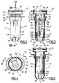
- FIG. 1 On the figure 1 is shown in perspective an injection device formed of a syringe 1 and a protection assembly 2.
- proximal and back are synonymous, as the terms “distal” and " before “.
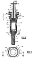
- Syringe 1 is a standard shaped glass syringe for single use. It contains a liquid to be injected, intramuscularly or subcutaneously, to a patient. It comprises for this purpose a body 4 and a needle 6 visible in particular on the Figure 6 . This needle is secured to the distal end of the body 4 by a collar 7.
- the syringe further comprises a piston 8 engaged in the body 4.
- This piston conventionally comprises a rod 10 provided at its distal end with a buffer 12 visible on the figure 6 and a support head 14 on which is intended to rest the thumb of the practitioner's hand.
- the rod 10 has in its common part a lower section than the buffer 12 so that a peripheral shoulder 15 visible on the figure 6 is formed on the pad 12 around the rod 10.
- the body 4 of the syringe has, in its proximal portion, a neck 16 delimiting circumferentially two diametrically opposite lugs 18, normally intended, especially in the absence of the assembly 2, to form bearing surfaces for the index and the middle finger of the practitioner during the manipulation of the syringe and the injection of the liquid therein.
- the needle 6 is protected by a removable cap 19 retained on the body of the syringe being engaged on the collar 7.
- the support 20 comprises a main section 26, substantially cylindrical and of internal diameter substantially equal to the outer diameter of the body 4 of the syringe.
- This section 26 has two longitudinal recesses 26A which are diametrically opposed.
- the section 26 is extended at its proximal end by a secondary section 28 of larger inside and outside diameters than those of the main section 26, forming a radial shoulder 29.
- the section 28 has an inside diameter greater than the maximum diameter of the neck 16 of the syringe.
- the proximal section 28 is provided with means 30 for retaining the pin 25 so that it encircles the syringe neck 16 between the shoulder 29 and the pin 25 as shown in FIG. figure 6 .
- the pin 25 visible on the Figure 4 is flat and has a form of hollow disc to create to form a U. It is delimited at its periphery by a circular contour 25A of diameter very slightly less than the inner diameter of the secondary section 28. It has a notch 25B engaging in the disc forming the pin beyond the center of it. This notch 25B opens radially to the periphery of the disc forming the pin. It has a semi-circular bottom 25C and two parallel banks 25D extending the bottom 25C. These banks 25D are extended to the periphery 25A of the disc by diverging flaps 25E so that the notch 25B flares near its emergent end.
- the diameter of the bottom 25C and the distance separating the ribs 25D, both designated D, are chosen to be greater than the diameter of the running portion of the piston rod 10, and smaller than the diameter of the pad 12 extending the rod 10.
- diameter D is smaller than the inner section of the syringe body 4.
- the retaining means 30 comprise diametrically opposed deformable hooks 32 which are carried by the section 28 of the protective support. These hooks are visible especially on figures 1 and 5 . The distance separating the diametrically opposite hooks is less than the outside diameter of the pin 25. Lights 34 are formed in the section 28 along the hooks 32 to give them elasticity.
- Each of these hooks includes a substantially frustoconical ramp 32A flaring towards the free end of the section 28. These ramps 32A are intended to allow to push the hooks outwardly elastically under the action of the pin 25 during the fixing the support 20 on the syringe 1.
- the hooks 32 are spaced from the shoulder 29 by a distance substantially equal to the cumulative thicknesses of the lugs 18 and the pin 25. The hooks 32 thus form a clipping means of the pin 25 for retaining the syringe neck 16.
- Each groove consists of a first rectilinear portion 38 which extends substantially along the axis XX of the support 20 on a length greater than that of the needle 6, and a second straight portion 40 which extends inclined relative to the same axis XX.
- the inclined portion 40 opens at the proximal end of the first rectilinear portion 38, forming a V whose tip is directed proximally of the assembly 2.
- the main section 26 has at its distal end a first pair of diametrically opposed elastic tongues 42, each located in the extension of the grooves 36 (FIG. figure 5 ).
- These tabs 42 have an inner face 42A of substantially cylindrical shape and an outer face substantially deflectable 42B diverging rearwardly.
- the main section 26 has a pair of diametrically opposed external ramps 44 situated between the elastic tongues 42 along the circumference of the distal end of this section. They have a substantially frustoconical inclined outer surface 44A, diverging forwards, and a substantially planar distal surface 44B. The outer surfaces 44A are thus turned towards the recesses 26A.
- the longitudinal recesses 26A are formed in the main section 26 ( figure 3 ) at the proximal end of these ramps 44.
- axial slots 26B are provided from the distal end of the support, so that before insertion of the body 4 of the syringe 1 into the support 20, these tongues 42 are radially deformable, in particular towards the inside.
- the main section 26 has, between the resilient tongues 42, two other tongues 45 of axial attachment of the protector 22 and the protective support 20 in the presence of the protective cap 19 placed on the syringe body.
- each tab 45A comprises a leg 45A extending the main section 26 and integral with it.
- Each leg 45A externally carries a projection 45B adapted to engage in a complementary lumen formed in the protector.
- the projections 45B are provided in half the length of the legs 45A extending from the leg connection region to the main section 26. Thus, the legs 45A extend beyond the projections 45B.
- the tongues are, at rest, inclined towards the axis XX of the support, that is to say that they converge towards one another towards their free end and they extend into the extension of the interior passage delimited by the protective support.
- tongues 45 are elastically deformable towards the outside so that, in the rest position, the projections are completely contained in the extension of the overall dimensions of the main section 26 whereas, in the deformed position, the projections 45B extend radially. outward beyond the extension of the overall bulk of the main section 26.
- the distance separating the free ends of the two tongues 45 when in their rest position is less than the minimum outer diameter of the retaining ring of the syringe protective cap 19.
- the protective sleeve 22 is of length substantially equal to that of the body 4 of the syringe. It consists of two cylindrical sections 46 and 48, the proximal section 46 having a diameter slightly greater than that of the main section 48. These two sections are connected by forming a radial shoulder 49.
- the sleeve 22 has integrally, in its proximal part, an outer collar 50 in the form of two diametrically opposed lugs 52 ( Figures 4 and 5 ).
- two diametrically opposite pins 54 are integral with the sleeve ( figure 5 ). These two nipples are received and guided in respectively the two grooves 36 of the support.
- the support and the sleeve are thus movable relative to each other in translation along their common axis and in limited rotation about the same axis when the pins are in the inclined portions 40.
- the inclined portions 40 then form pockets of retention of the nipples 54, these pockets having a retention depth noted p on the Figure 3 . This depth is measured along the axis of the protector.
- the support 20 and the sleeve 22 are movable between a retracted position of the sleeve, in which the bulk of the sleeve covers the bulk of the support and the pins 54 are located at the distal end of each of the inclined groove portions 40, such as represented on the Figures 2 to 8 , and an extended position of the sleeve in which it extends axially projecting from the support and the nipples are located at the distal end of the straight groove portion 38, as shown in FIGS. Figures 13 to 15 .
- these extreme positions respectively correspond to an injection configuration in which the needle 6 of the syringe 1 is disengaged and intended to be inserted into a patient, and to a protective configuration wherein this needle is surrounded by the protective sleeve 22.
- the proximal portion of the sleeve 22 further comprises internally a pair of deformable longitudinal hooks 56 diametrically opposed. These hooks are delimited in the sleeve 22 by lateral slots. They are linked to the sleeve at their distal end. Each hook has at its proximal free end an inner protuberance.
- each protuberance has a front face 56A of substantially frustoconical shape deviating towards the front of the axis of the sleeve 22. These front faces 56A are thus turned towards the front end of the protector.
- Each front face 56A is adapted to cooperate with an inclined surface 44A formed by the ramps 44 of the support.
- each hook 56 has an inclined transverse front 56C forming a stop.
- the hooks 56 In the retracted position of the sleeve, the hooks 56 extend inside the recesses 26A formed in the support 20. In the extended position of the sleeve, as shown in FIG. figure 13 , the end faces 56C of the hooks 56 are in axial abutment against the tabs 42, the hooks and tongues thereby forming a rigid locking assembly in the deployed position.
- the sleeve 22 is furthermore provided at its distal end with a ring of deformable tongues 58, the distal edges of which form a substantially circular opening 60 of diameter smaller than the inside diameter of the main section 26 of the support 20.
- the main section 48 of the protective sleeve comprises two oblong through slots 62 adapted to receive the projections 45B carried by the second pair of tongues 45 when they are deformed under the action of the ring of the cap 19 needle protection engaged on a syringe contained in the device.
- the spring 24 is a spiral spring disposed between the protective sleeve 22 and the protective support 20. More specifically, the spring is housed between the shoulder 29 of the support 20 and the shoulder 49 of the sleeve 22.
- the spring 24 In the retracted position of the sleeve, the spring 24 is in a compressed state, thus having a decompression energy related to the stiffness of the spring and the difference between the length of the spring at rest state and its length, noted L on the Figures 2 to 8 in the compressed state. That is to say that the spring 24 has a threshold of additional compression force which corresponds to the minimum force required to compress the spring further from its initial compressed state of Figures 2 to 8 .
- the stiffness of the spring and / or the initial compression length L are chosen such that this force threshold is greater than the thrust force necessary to move the piston 8 of the syringe 1 over its entire injection stroke.
- the spring force in the locked state is greater than the sum of the injection force, that is to say the discharge of the liquid outside the needle 6 of the syringe 1 , and stresses of delamination and sliding of the pusher 12 inside the body 4 of the syringe.
- the cap 19 is of tubular general shape, and is shown on the figures 1 and 6 .
- This cap is closed at one of its ends and its opposite end is formed by an annular ring 68 of external diameter adapted to both be conjugated to the surface 42A tabs 42 and be greater than the diameter of the opening 60 formed by the tabs 58 of the protective sleeve 22.
- the inner face of this ring 68 is intended to adhere to the glass collar 7 of the syringe body where the needle is fixed. 6, especially to ensure a certain tightness to bacteria.
- the outer diameter of the ring 68 of the cap is greater than the distance separating at rest the free ends of the tongues 45.
- the operation of the injection device according to the invention is as follows.
- the protection device 2 is assembled in its retracted configuration, that is to say that of the Figures 2 to 8 .
- the protective sleeve 22 is therefore threaded around the support 20 from the distal end of the support, by placing the spring 24 between them. More precisely, the sleeve 22 is moved axially backwards relative to the support, while deforming the hooks 56 radially outwardly by means of a suitable tool, and at least until they reach axially the front part of the longitudinal recesses 26A.
- the glass syringe 1 is pre-filled with a liquid to be injected into a patient.
- This syringe is equipped with the cap 19 which encloses the collar 9 of the syringe body 4.
- the syringe equipped with the cap 19 is inserted inside the assembly 2 to form the injection device, as shown in FIGS. Figures 6 and 7 . More specifically, the body 4 of the syringe is displaced substantially axially inside the support 20.
- the movement of the syringe body in the protector is carried out until the syringe neck 16 bears on the shoulder 29.
- the pin 25 is then attached to the neck 16.
- the pin 25 is engaged around the piston rod, the latter lying in the notch.
- the pin 25 is moved along the length of the rod 10 and is engaged in the main section 28 by deforming radially outwardly the hooks 32 so as to ensure an elastic engagement of the pin.
- the ears 18 of the syringe neck 16 are then retained axially by the pin 25 itself retained by the hooks 32.
- the syringe neck 16 is fully clipped inside the section 28, it can no longer fulfill its usual role of forming a bearing surface for the practitioner's index finger and middle finger.
- This support function is performed by the collar 50 integral with the sleeve 22.
- the length of the protective sleeve 22 is substantially equal to that of the syringe body 4 and / or where the flange 50 is formed at the level of of the proximal end of this sleeve, the practitioner can then manipulate the syringe by resting his thumb on the bearing head 14 of the piston 8 as usual, and resting his forefinger and middle finger on the faces of the ears 52 directed towards the needle 6.
- the enlarged outer diameter of the ring 68 of the cap is engaged between the free ends of the tongues 45, which thus ensures their radial deformation to the outside.
- the projections 45B are received in the slots 62.
- the cooperation of the protrusions 45B carried by the protective support and the slots 62 formed in the protector ensures an axial connection of the protector and the support , thus prohibiting release of the spring, the pin 54 can not leave the end of the stick in which it is engaged.
- the practitioner can hold the syringe by holding the protector with one hand from the bearing surfaces 50 and pull the cap 19 with the other hand. Even if the resistance to removal of the cap is very important, the positive axial connection provided by the projections 45B engaged in the slots 62 prevents the spring 24 can be compressed and the pins 54 can be released from the retaining stock.
- the protector 22 can be moved relative to the support 20 since the tongues 45 resume their rest position under the action of their elasticity and the projections 45A are then disengaged from the lights 62.
- the ring 68 After detachment of the ring 68 of the collar 9, the ring 68 passes through the opening 60 by deforming the tongues 58. Once the cap 19 has been removed, the tongues 58 return to their initial position.
- the practitioner may then be required to perform an operation known as "vein test”. This consists of checking that the syringe has been correctly stitched into a muscle of the patient and not into an artery or a vein. For this purpose, the piston 8 is pulled towards the proximal end. If blood is drawn into the syringe body, the practitioner deduces that the needle is stitched into a vein or artery and then starts the needle again.
- vehicle test This consists of checking that the syringe has been correctly stitched into a muscle of the patient and not into an artery or a vein.
- the piston 8 is pulled towards the proximal end. If blood is drawn into the syringe body, the practitioner deduces that the needle is stitched into a vein or artery and then starts the needle again.
- the buffer 12 In case of excessive traction exerted by the practitioner on the piston rod, the buffer 12 is stopped in its movement by abutting by through the shoulder 15 against the pin 25 as shown in FIG. figure 9 .
- the notch 25B defines a section of passage smaller than the section of the pad 12 so that it can not pass beyond the pin.
- the piston rod 10 having a smaller diameter, it can slide freely through the notch 25B.
- the pin 25 ensures both the retention of the syringe body 4 in the protector and secondly constitutes a stop stop buffer 12 in case of excessive traction thereon. In the absence of the pin, the tampon could be removed from the syringe body, thus rendering the injection device unusable.
- Stopping the piston in case of excessive traction on it is also useful when filling the syringe through the needle for example during a lyophilisate recovery.
- the practitioner expels the liquid contained in the syringe by exerting a thrust on the bearing head 14 of the piston, his forefinger and middle finger remaining in contact with the faces directed towards the needle of the ears 52.
- the spring 24 remaining compressed with a length L, as shown in FIG. figure 8 .
- the practitioner then removes the needle from the patient.
- the practitioner exerts an additional pressure on the piston rod 8.
- This pressure must be greater than the predetermined force produced by the spring 24 in the locked state, so that this spring is more compressed and passes from its length L to a length The smallest, as represented on the Figures 10 to 12 .
- the protective sleeve 22 moves axially toward the proximal end of the support 20. The practitioner performs this movement by exerting a corresponding pressure by means of his index finger and his middle finger on the ears 52 of the collar 50 of the sleeve 22.
- This pressure causes, in combination with the translational movement, the rotation of the protective sleeve 22 around the syringe holder 20, the pins 54 being guided by the inclined groove portions 40.
- This rotational movement continues until the nipples reach the proximal end of this groove portion 40, i.e., the proximal end of the longitudinal groove portion. 38, as visible on the figure 11 .
- the device 2 is then in the unlocking position of the spring 24.
- the pins 54 move in translation within the longitudinal groove portion 38 to the distal end thereof as shown in FIGS. Figures 13 to 15 .
- the translational movement of the protective sleeve 22 relative to the support 20 is controllable by the practitioner, if the latter gradually releases the digital retainer that the collar 50 exerts.
- the nipples 54 have arrived at the distal end of the groove 36 ( figure 15 ), the protector is in its deployed position.
- the hooks 56 borrow the longitudinal recesses 26A of the support, until they slide along the distal ramps 44 of the support, by cooperation of their complementary surfaces 56A and 44A.
- the hooks 56 are held by cooperation of the surfaces 56C and 44B, so that the protective sleeve 22 can not be returned to its initial position.
- the sleeve 22 can not be easily torn off the support 20 since the pins 54 abut against the distal bottom of the longitudinal groove portion 38 (FIG. figure 15 ), the tabs 42 forming this bottom being radially held between the body of the syringe 1 and the protective sleeve 22.
- the injection device according to the invention is thus easy to use, while allowing the practitioner to control the movement of recovery of the needle by the protective sleeve.
- the number of parts of which is constituted the protection assembly 2 represented is reduced to three.
- the device according to the invention is adaptable to different types of syringes, both in terms of shapes and volumes. This device therefore has the advantage of not calling into question the general shape of the syringes used and therefore does not result in any modification of the industrial processes for filling these syringes.
Landscapes
- Health & Medical Sciences (AREA)
- Engineering & Computer Science (AREA)
- Hematology (AREA)
- Anesthesiology (AREA)
- Biomedical Technology (AREA)
- Heart & Thoracic Surgery (AREA)
- Vascular Medicine (AREA)
- Life Sciences & Earth Sciences (AREA)
- Animal Behavior & Ethology (AREA)
- General Health & Medical Sciences (AREA)
- Public Health (AREA)
- Veterinary Medicine (AREA)
- Environmental & Geological Engineering (AREA)
- Infusion, Injection, And Reservoir Apparatuses (AREA)
- Nozzles (AREA)
Claims (6)
- Injektionsvorrichtung, Folgendes umfassend:- eine Injektionsspritze (1), die aufweist:• einen rohrförmigen Spritzenkörper (4), der an einem proximalen Ende mit einem Halteansatz (16) ausgestattet ist, der radial nach außen vorsteht; und• einen Injektionskolben (8), der verschiebbar im Körper (4) angebracht ist, wobei er vom proximalen Ende des Körpers (4) her in den Körper eingeführt ist,- eine Nadelschutzeinrichtung (2), die Folgendes umfasst:• einen Schutzträger (20), der einen Aufnahmekanal des Spritzenkörpers (4) abgrenzt, welcher Schutzträger (20) Mittel (30) zum axialen Halten des Körpers (4) in Bezug auf den Schutzträger (20) umfasst,• eine Nadelschutzvorrichtung (22) die in Bezug auf den Schutzträger (20) zwischen einer eingefahrenen Position und einer ausgefahrenen Position verlagerbar ist,
dadurch gekennzeichnet, dass:- der Kolben (8) ein distales Ende (14) umfasst, das in den Spritzenkörper (4) eingesteckt und zum proximalen Ende hin durch einen gängigen Abschnitt (10) des Kolbens verlängert ist, wobei eine zum proximalen Ende hin gewandte Schulter (15) zwischen dem distalen Ende (14) und dem gängigen Abschnitt (10) des Kolbens definiert ist, und- die Injektionsvorrichtung einen Anschlagstift (25) zum Stoppen des Kolbens (8) umfasst, welcher Stift (25) vom Schutzträger (20) getragen ist und in der Verlängerung des Spritzenkörpers (4) einen Zirkulationsdurchgang (25B) des Kolbens (8) definiert, dessen Mindestquerschnitt größer als der Querschnitt des gängigen Abschnitts (10) des Kolbens (8) und kleiner als der Querschnitt der Schulter (15) des Kolbens ist,- der Stift (25) eine Ausklinkung (25B) abgrenzt, die sich radial öffnet, und deren Grund (25C) den Zirkulationsdurchgang des Kolbens (8) abgrenzt, und- der Schutzträger (20) elastische Einrastmittel (32) des Stifts (25) für dessen axialen Halt umfasst. - Injektionsvorrichtung nach Anspruch 1, dadurch gekennzeichnet, dass der Abstand der die Ausklinkung abgrenzenden Ränder (25D) größer als der Durchmesser des gängigen Abschnitts des Kolbens (10) und kleiner als der Innenquerschnitt des Spritzenkörpers (4) gewählt ist.
- Injektionsvorrichtung nach Anspruch 1 oder 2, dadurch gekennzeichnet, dass die elastischen Einrastmittel Einrastvorsprünge (32) umfassen, die vom Schutzträger (20) getragen sind, wobei der Abstand zwischen den Einrastvorsprüngen (32) größer ist als der Querschnitt des Spritzenkörpers, um ein freies Einstecken des Spritzenkörpers (4) in den Schutzträger (20) zuzulassen.
- Injektionsvorrichtung nach Anspruch 3, dadurch gekennzeichnet, dass Öffnungen (34) entlang den Einrastvorsprüngen (32) ausgebildet sind, um ihnen Elastizität zu verleihen.
- Injektionsvorrichtung nach einem der vorhergehenden Ansprüche, dadurch gekennzeichnet, dass der Schutzträger (20) einen Anschlag (29) zur axialen Anlage des Spritzenkörpers (4) zum proximalen Ende hin umfasst, und dass der Stift (25) zum proximalen Ende hin axial mit dem Schutzträger (20) verbunden ist und einen Stoppanschlag für den Kragen (16) zum proximalen Ende hin bildet, so dass der Ansatz (16) axial zwischen dem Anlageanschlag (29) und dem Stift (25) eingeschlossen ist.
- Injektionsvorrichtung nach einem der vorhergehenden Ansprüche, dadurch gekennzeichnet, dass der Stift (25) eine kreisförmige Außenkontur aufweist.
Applications Claiming Priority (3)
| Application Number | Priority Date | Filing Date | Title |
|---|---|---|---|
| FR0409162A FR2874505B1 (fr) | 2004-08-27 | 2004-08-27 | Dispositif d'injection comprenant une seringue |
| FR0409163A FR2874506B1 (fr) | 2004-08-27 | 2004-08-27 | Dispositif de protection d'aiguille destine a une seringue, et dispositif d'injection le comprenant |
| PCT/FR2005/001926 WO2006027445A1 (fr) | 2004-08-27 | 2005-07-25 | Dispositif d’injection comprenant une seringue |
Publications (2)
| Publication Number | Publication Date |
|---|---|
| EP1786497A1 EP1786497A1 (de) | 2007-05-23 |
| EP1786497B1 true EP1786497B1 (de) | 2013-03-27 |
Family
ID=42752266
Family Applications (2)
| Application Number | Title | Priority Date | Filing Date |
|---|---|---|---|
| EP05792448A Expired - Lifetime EP1786497B1 (de) | 2004-08-27 | 2005-07-25 | Injektionsvorrichtung mit spritze |
| EP05793388A Expired - Lifetime EP1781359B1 (de) | 2004-08-27 | 2005-07-28 | Schutzvorrichtung für spritzennadel und injektionsvorrichtung damit |
Family Applications After (1)
| Application Number | Title | Priority Date | Filing Date |
|---|---|---|---|
| EP05793388A Expired - Lifetime EP1781359B1 (de) | 2004-08-27 | 2005-07-28 | Schutzvorrichtung für spritzennadel und injektionsvorrichtung damit |
Country Status (6)
| Country | Link |
|---|---|
| US (2) | US7938808B2 (de) |
| EP (2) | EP1786497B1 (de) |
| AT (1) | ATE394135T1 (de) |
| DE (1) | DE602005006580D1 (de) |
| FR (2) | FR2874505B1 (de) |
| WO (2) | WO2006027445A1 (de) |
Families Citing this family (74)
| Publication number | Priority date | Publication date | Assignee | Title |
|---|---|---|---|---|
| US8562583B2 (en) | 2002-03-26 | 2013-10-22 | Carmel Pharma Ab | Method and assembly for fluid transfer and drug containment in an infusion system |
| US7867215B2 (en) | 2002-04-17 | 2011-01-11 | Carmel Pharma Ab | Method and device for fluid transfer in an infusion system |
| SE523001C2 (sv) | 2002-07-09 | 2004-03-23 | Carmel Pharma Ab | En kopplingsdel, en koppling, en infusionspåse, en infusionsanordning och ett förfarande för överföring av medicinska substanser |
| JP5148107B2 (ja) | 2003-01-21 | 2013-02-20 | カルメル ファルマ アクチボラゲット | 膜を突き刺すための針 |
| FR2852851B1 (fr) | 2003-03-25 | 2006-01-06 | Sedat | Dispositif de protection d'aiguille destine a une seringue, et dispositif d'injection comprenant une seringue et ce dispositif de protection |
| FR2861310B1 (fr) | 2003-10-22 | 2006-09-22 | Plastef Investissements | Dispositif de seringue d'injection securise |
| US7294119B2 (en) * | 2004-06-10 | 2007-11-13 | Safety Syringes, Inc. | Passive delivery system diluents mixing and delivery |
| US11590286B2 (en) | 2004-11-22 | 2023-02-28 | Kaleo, Inc. | Devices, systems and methods for medicament delivery |
| US10737028B2 (en) | 2004-11-22 | 2020-08-11 | Kaleo, Inc. | Devices, systems and methods for medicament delivery |
| AU2004325202B2 (en) | 2004-11-22 | 2009-02-19 | Kaleo, Inc. | Devices, systems, and methods for medicament delivery |
| US7648483B2 (en) | 2004-11-22 | 2010-01-19 | Intelliject, Inc. | Devices, systems and methods for medicament delivery |
| DK2058020T3 (da) | 2005-02-01 | 2013-01-07 | Intelliject Inc | Indretning til indgivelse af lægemiddel |
| GB0600212D0 (en) * | 2006-01-06 | 2006-02-15 | Liversidge Barry P | Medical needle safety device |
| US8888713B2 (en) | 2007-03-07 | 2014-11-18 | Becton, Dickinson And Company | Safety blood collection assembly with indicator |
| MX340160B (es) | 2007-03-07 | 2016-06-29 | Becton Dickinson And Company * | Conjunto de seguridad para recoleccion de sangre con indicador. |
| US7942860B2 (en) | 2007-03-16 | 2011-05-17 | Carmel Pharma Ab | Piercing member protection device |
| US7975733B2 (en) | 2007-05-08 | 2011-07-12 | Carmel Pharma Ab | Fluid transfer device |
| US9044378B2 (en) * | 2007-05-31 | 2015-06-02 | Safety Syringes, Inc. | Anti-needle stick safety device or system for use with drugs requiring reconstitution |
| US8622985B2 (en) | 2007-06-13 | 2014-01-07 | Carmel Pharma Ab | Arrangement for use with a medical device |
| US8029747B2 (en) | 2007-06-13 | 2011-10-04 | Carmel Pharma Ab | Pressure equalizing device, receptacle and method |
| US8657803B2 (en) | 2007-06-13 | 2014-02-25 | Carmel Pharma Ab | Device for providing fluid to a receptacle |
| JP4566223B2 (ja) * | 2007-08-02 | 2010-10-20 | 株式会社アルテ | 容器兼用注射器 |
| GB2452030A (en) * | 2007-08-10 | 2009-02-25 | Owen Mumford Ltd | Injection devices |
| US10398834B2 (en) | 2007-08-30 | 2019-09-03 | Carmel Pharma Ab | Device, sealing member and fluid container |
| US8287513B2 (en) | 2007-09-11 | 2012-10-16 | Carmel Pharma Ab | Piercing member protection device |
| JP5329546B2 (ja) | 2007-09-17 | 2013-10-30 | カルメル ファルマ アクチボラゲット | バッグコネクタ |
| FR2922455B1 (fr) | 2007-10-23 | 2010-10-29 | Plastef Investissements | Dispositif de seringue comprenant un corps de seringue et un manchon de support. |
| FR2922457B1 (fr) | 2007-10-23 | 2010-10-29 | Plastef Investissements | Dispositif de seringue a capuchon de protection. |
| FR2925342B1 (fr) * | 2007-12-21 | 2011-01-21 | Rexam Pharma La Verpilliere | Dispositif d'injection d'un implant |
| ES2589322T3 (es) * | 2008-02-11 | 2016-11-11 | Safety Syringes, Inc. | Jeringa con protector de seguridad de aguja y clip para evitar la liberación del protector durante un proceso de reconstitución |
| US8795198B2 (en) | 2008-03-07 | 2014-08-05 | Becton, Dickinson And Company | Flashback blood collection needle |
| US8603009B2 (en) | 2008-03-07 | 2013-12-10 | Becton, Dickinson And Company | Flashback blood collection needle |
| JP2009240411A (ja) * | 2008-03-28 | 2009-10-22 | Terumo Corp | 医薬品容器 |
| US8075550B2 (en) * | 2008-07-01 | 2011-12-13 | Carmel Pharma Ab | Piercing member protection device |
| US8523838B2 (en) | 2008-12-15 | 2013-09-03 | Carmel Pharma Ab | Connector device |
| US8790330B2 (en) | 2008-12-15 | 2014-07-29 | Carmel Pharma Ab | Connection arrangement and method for connecting a medical device to the improved connection arrangement |
| CN104606745B (zh) | 2009-07-23 | 2017-07-28 | 适宜卫生科技项目公司 | 皮内注射适配器、皮内注射组件和皮内注射输送的注射器组件 |
| US9526846B2 (en) | 2009-08-19 | 2016-12-27 | Safety Syringes, Inc. | Patient-contact activated needle stick safety device |
| USD637713S1 (en) | 2009-11-20 | 2011-05-10 | Carmel Pharma Ab | Medical device adaptor |
| US8480646B2 (en) | 2009-11-20 | 2013-07-09 | Carmel Pharma Ab | Medical device connector |
| GB2478349A (en) * | 2010-03-05 | 2011-09-07 | Owen Mumford Ltd | Injection device having projections reducing the diameter of the syringe passage |
| EP2544734B1 (de) | 2010-03-12 | 2016-03-09 | Sid Technologies LLC | Anordnung zur verwendung mit einer spritze |
| US20130012886A1 (en) * | 2010-03-18 | 2013-01-10 | Daikyo Seiko, Ltd. | Syringe needle cap |
| US8162013B2 (en) | 2010-05-21 | 2012-04-24 | Tobias Rosenquist | Connectors for fluid containers |
| US9168203B2 (en) | 2010-05-21 | 2015-10-27 | Carmel Pharma Ab | Connectors for fluid containers |
| US8939943B2 (en) | 2011-01-26 | 2015-01-27 | Kaleo, Inc. | Medicament delivery device for administration of opioid antagonists including formulations for naloxone |
| US9173999B2 (en) * | 2011-01-26 | 2015-11-03 | Kaleo, Inc. | Devices and methods for delivering medicaments from a multi-chamber container |
| WO2012138318A1 (en) | 2011-04-04 | 2012-10-11 | West Pharmaceutical Services, Inc. | Needle safety shield |
| US9867940B2 (en) * | 2011-12-15 | 2018-01-16 | Shl Group Ab | Auto-injection device |
| US9050416B2 (en) | 2012-11-01 | 2015-06-09 | Tech Group Europe Limited | Needle Safety device with floating ring |
| USD712360S1 (en) * | 2013-02-06 | 2014-09-02 | Nextronics Engineering Corp. | Circular connector |
| WO2014151665A1 (en) | 2013-03-14 | 2014-09-25 | Boston Scientific Scimed, Inc. | Injection devices with controllable depth adjustability and methods of use |
| US9474865B2 (en) * | 2013-04-25 | 2016-10-25 | West Pharmaceutical Services, Inc. | Needle shield for disposable syringe with annular ring |
| US10524833B2 (en) * | 2013-11-04 | 2020-01-07 | Fnapen Llc | Device and methods for precise control of medical procedures |
| DK3137136T3 (en) * | 2014-04-29 | 2018-07-23 | Carebay Europe Ltd | DEVICE FOR ADJUSTING DEADLINE DEPTH |
| CN107427639B (zh) * | 2015-03-24 | 2020-10-02 | 泰尔茂株式会社 | 注射器保持器和给药组件 |
| USD765838S1 (en) | 2015-03-26 | 2016-09-06 | Tech Group Europe Limited | Syringe retention clip |
| AU2016287571C1 (en) | 2015-06-30 | 2021-12-23 | Kaleo, Inc. | Auto-injectors for administration of a medicament within a prefilled syringe |
| FR3038840B1 (fr) * | 2015-07-16 | 2017-07-21 | Nemera La Verpilliere | Dispositif de securite pour une seringue d'injection. |
| CA3027992C (en) | 2016-06-22 | 2021-08-03 | Antares Pharma, Inc. | Needle-shield remover |
| CA2971263A1 (en) * | 2017-06-19 | 2018-12-19 | Duoject Medical Systems Inc. | Injector for drugs |
| EP3664873B1 (de) * | 2017-08-11 | 2021-04-07 | West Pharmaceutical Services, Inc. | Integriertes passives spritzennadelsicherheitssystem mit angezogener druckfeder und mehrteiliger manschette |
| EP3902584A4 (de) | 2018-12-29 | 2022-09-07 | Kaleo, Inc. | Vorrichtungen und verfahren zur abgabe von substanzen in einer vorgefüllten spritze |
| US11167087B2 (en) | 2019-08-09 | 2021-11-09 | Kaleo, Inc. | Devices and methods for delivery of substances within a prefilled syringe |
| EP4051347B1 (de) * | 2019-11-01 | 2025-09-24 | Tech Group Europe Limited | Nadelschutzvorrichtung mit spritzenzentriermerkmalen und demontagesicherung |
| JP1691364S (de) | 2019-11-01 | 2021-08-02 | ||
| EP4070836A4 (de) | 2019-12-10 | 2023-12-13 | Nipro Corporation | Spritze mit sicherheitsmechanismus |
| US12005244B2 (en) | 2020-03-27 | 2024-06-11 | Medivena Sp. Z O.O. | Needle-based device based on direct wing-based coupling of a needle shield to a barrel thereof and safety mechanism implemented therein |
| WO2021247039A1 (en) * | 2020-06-05 | 2021-12-09 | Garwood Medical Devices, Llc | Subdermal needle electrode apparatus for biofilm infection control |
| FR3119331B1 (fr) * | 2021-02-02 | 2023-03-24 | Olivier Banville | Dispositif de sécurité pour seringue à usage unique |
| US12268847B1 (en) | 2021-02-10 | 2025-04-08 | Kaleo, Inc. | Devices and methods for delivery of substances within a medicament container |
| WO2024126093A1 (en) * | 2022-12-15 | 2024-06-20 | Shl Medical Ag | Safety injection device for delivering a drug |
| USD1109322S1 (en) | 2023-10-02 | 2026-01-13 | Regeneron Pharmaceuticals, Inc. | Drug-delivery device |
| USD1108627S1 (en) | 2023-10-02 | 2026-01-06 | Regeneron Pharmaceuticals, Inc. | Drug-delivery device |
Family Cites Families (20)
| Publication number | Priority date | Publication date | Assignee | Title |
|---|---|---|---|---|
| US4927416A (en) * | 1987-12-02 | 1990-05-22 | National Medical Device Corporation | User-protective hypodermic syringe holder |
| US5141500A (en) * | 1989-03-02 | 1992-08-25 | Lawrence W. Hake | Hypodermic needle guard |
| ES2082052T3 (es) * | 1990-07-19 | 1996-03-16 | Nardino Righi | Jeringuilla de seguridad, de un solo uso. |
| US5201720A (en) * | 1992-04-21 | 1993-04-13 | Joseph Borgia | Syringe holding and ejecting assembly |
| US5803918A (en) * | 1993-05-06 | 1998-09-08 | Becton Dickinson And Company | Syringe for medicinal purposes |
| ZA964503B (en) * | 1995-06-02 | 1996-12-09 | Louis Hubert Jacobs | Medical apparatus |
| US5591138A (en) * | 1995-08-10 | 1997-01-07 | Vaillancourt; Vincent L. | Protected needle assembly |
| US5817064A (en) * | 1995-10-23 | 1998-10-06 | American Home Products Corporation | Syringe needle guard |
| US5997513A (en) * | 1995-11-22 | 1999-12-07 | Smith; Jerry A. | Syringe cover cooperating with needle cover |
| FR2757067B1 (fr) * | 1996-12-17 | 1999-07-16 | Sedat | Seringue d'injection a protecteur d'aiguille deplacable |
| US6159184A (en) * | 1997-03-10 | 2000-12-12 | Safety Syringes, Inc. | Disposable self-shielding unit dose syringe guard |
| US5951526A (en) * | 1997-09-24 | 1999-09-14 | Korisch; Marina | Syringe holder with integral dose divider |
| DE19929325A1 (de) * | 1999-06-26 | 2001-01-18 | Vetter & Co Apotheker | Spritze für medizinische Zwecke |
| FR2799376B1 (fr) * | 1999-10-07 | 2002-01-18 | Marc Brunel | Dispositif d'injection a usage unique |
| JP2003523804A (ja) * | 2000-01-27 | 2003-08-12 | アフラ デザイン ピーティーワイ.リミティッド | 一回使用の注射器 |
| US6416323B1 (en) * | 2000-05-11 | 2002-07-09 | Safety Syringes, Inc. | Aspirating dental syringe with needle shield |
| GB0110443D0 (en) * | 2001-04-28 | 2001-06-20 | Owen Mumford Ltd | Improvements relating to syringe holders |
| FR2835753B1 (fr) * | 2002-02-11 | 2004-10-29 | Plastef Investissements | Dispositif de support de securite pour une seringue et ensemble d'un tel dispositif et d'une seringue |
| FR2837107B1 (fr) * | 2002-03-18 | 2005-02-25 | Sedat | Dispositif de protection d'aiguille destine a une seringue, et dispositif d'injection comprenant une seringue et ce dispositif de protection |
| US20030187401A1 (en) * | 2002-03-27 | 2003-10-02 | Safety Syringes, Inc. | Syringe with integral safety system |
-
2004
- 2004-08-27 FR FR0409162A patent/FR2874505B1/fr not_active Expired - Lifetime
- 2004-08-27 FR FR0409163A patent/FR2874506B1/fr not_active Expired - Fee Related
-
2005
- 2005-07-25 US US11/574,176 patent/US7938808B2/en active Active
- 2005-07-25 EP EP05792448A patent/EP1786497B1/de not_active Expired - Lifetime
- 2005-07-25 WO PCT/FR2005/001926 patent/WO2006027445A1/fr not_active Ceased
- 2005-07-28 AT AT05793388T patent/ATE394135T1/de not_active IP Right Cessation
- 2005-07-28 EP EP05793388A patent/EP1781359B1/de not_active Expired - Lifetime
- 2005-07-28 US US11/574,333 patent/US8192407B2/en active Active
- 2005-07-28 WO PCT/FR2005/001983 patent/WO2006027447A1/fr not_active Ceased
- 2005-07-28 DE DE602005006580T patent/DE602005006580D1/de not_active Expired - Lifetime
Also Published As
| Publication number | Publication date |
|---|---|
| DE602005006580D1 (de) | 2008-06-19 |
| ATE394135T1 (de) | 2008-05-15 |
| FR2874505B1 (fr) | 2007-06-08 |
| FR2874505A1 (fr) | 2006-03-03 |
| WO2006027445A1 (fr) | 2006-03-16 |
| EP1786497A1 (de) | 2007-05-23 |
| EP1781359B1 (de) | 2008-05-07 |
| US20070270759A1 (en) | 2007-11-22 |
| US20070265576A1 (en) | 2007-11-15 |
| WO2006027447A1 (fr) | 2006-03-16 |
| US7938808B2 (en) | 2011-05-10 |
| US8192407B2 (en) | 2012-06-05 |
| EP1781359A1 (de) | 2007-05-09 |
| FR2874506B1 (fr) | 2007-06-08 |
| FR2874506A1 (fr) | 2006-03-03 |
Similar Documents
| Publication | Publication Date | Title |
|---|---|---|
| EP1781359B1 (de) | Schutzvorrichtung für spritzennadel und injektionsvorrichtung damit | |
| EP1485153B1 (de) | Nadelschutzvorrichtung für eine spritze sowie injektionsvorrichtung bestehend aus einer spritze und dieser schutzvorrichtung | |
| EP1605997B1 (de) | Nadelschutzvorrichtung für eine spritze, und injektionsvorrichtung mit einer spritze und dieser nadelschutzvorrichtung | |
| EP1532997B1 (de) | Nadelschutzvorrichtung für eine Karpulle | |
| EP1027902B1 (de) | Injektionsspritze mit Selbstschutz | |
| EP1330279B1 (de) | Injektionsspritze mit einem verschiebbaren nadelschutz | |
| EP1436026B1 (de) | Sicherheitsvorrichtung für eine spritze | |
| EP1148904B9 (de) | Sicherheitsanordnung für spritze vorgefüllt mit flüssigem arzneimittel | |
| FR2922112A1 (fr) | Dispositif de securite pour une seringue d'injection de liquide et ensemble a seringue comprenant ce dispositif | |
| FR2959419A1 (fr) | Dispositif de securite pour seringue d'injection pre-remplie | |
| WO1989000432A2 (fr) | Seringue de haute securite non reutilisable | |
| EP3544660B1 (de) | Injektionsvorrichtung mit verbesserter spritzenkappenentfernung | |
| WO2003045481A1 (fr) | Dispositif de securite pour seringue d'injection par voie parenterale, a usage unique | |
| EP1356839B1 (de) | Anordnung einer Flüssigkeitsinjektionsspritze und Hülse für diese Anordnung | |
| WO2017140962A1 (fr) | Dispositif d'injection d'un produit liquide à assemblage simplifié | |
| FR2881053A1 (fr) | Dispositif de protection d'aiguille destine a une seringue, et ensemble d'injection associe | |
| FR2622804A1 (fr) | Seringue non reutilisable | |
| FR3038840A1 (fr) | Dispositif de securite pour une seringue d'injection. |
Legal Events
| Date | Code | Title | Description |
|---|---|---|---|
| PUAI | Public reference made under article 153(3) epc to a published international application that has entered the european phase |
Free format text: ORIGINAL CODE: 0009012 |
|
| 17P | Request for examination filed |
Effective date: 20070222 |
|
| AK | Designated contracting states |
Kind code of ref document: A1 Designated state(s): AT BE BG CH CY CZ DE DK EE ES FI FR GB GR HU IE IS IT LI LT LU LV MC NL PL PT RO SE SI SK TR |
|
| DAX | Request for extension of the european patent (deleted) | ||
| 17Q | First examination report despatched |
Effective date: 20090911 |
|
| RAP1 | Party data changed (applicant data changed or rights of an application transferred) |
Owner name: TECH GROUP EUROPE LIMITED |
|
| GRAP | Despatch of communication of intention to grant a patent |
Free format text: ORIGINAL CODE: EPIDOSNIGR1 |
|
| GRAP | Despatch of communication of intention to grant a patent |
Free format text: ORIGINAL CODE: EPIDOSNIGR1 |
|
| GRAS | Grant fee paid |
Free format text: ORIGINAL CODE: EPIDOSNIGR3 |
|
| GRAA | (expected) grant |
Free format text: ORIGINAL CODE: 0009210 |
|
| AK | Designated contracting states |
Kind code of ref document: B1 Designated state(s): AT BE BG CH CY CZ DE DK EE ES FI FR GB GR HU IE IS IT LI LT LU LV MC NL PL PT RO SE SI SK TR |
|
| REG | Reference to a national code |
Ref country code: GB Ref legal event code: FG4D Free format text: NOT ENGLISH |
|
| REG | Reference to a national code |
Ref country code: CH Ref legal event code: EP |
|
| REG | Reference to a national code |
Ref country code: AT Ref legal event code: REF Ref document number: 602974 Country of ref document: AT Kind code of ref document: T Effective date: 20130415 |
|
| REG | Reference to a national code |
Ref country code: IE Ref legal event code: FG4D Free format text: LANGUAGE OF EP DOCUMENT: FRENCH |
|
| REG | Reference to a national code |
Ref country code: DE Ref legal event code: R096 Ref document number: 602005038798 Country of ref document: DE Effective date: 20130523 |
|
| PG25 | Lapsed in a contracting state [announced via postgrant information from national office to epo] |
Ref country code: SE Free format text: LAPSE BECAUSE OF FAILURE TO SUBMIT A TRANSLATION OF THE DESCRIPTION OR TO PAY THE FEE WITHIN THE PRESCRIBED TIME-LIMIT Effective date: 20130327 Ref country code: LT Free format text: LAPSE BECAUSE OF FAILURE TO SUBMIT A TRANSLATION OF THE DESCRIPTION OR TO PAY THE FEE WITHIN THE PRESCRIBED TIME-LIMIT Effective date: 20130327 Ref country code: BG Free format text: LAPSE BECAUSE OF FAILURE TO SUBMIT A TRANSLATION OF THE DESCRIPTION OR TO PAY THE FEE WITHIN THE PRESCRIBED TIME-LIMIT Effective date: 20130627 |
|
| REG | Reference to a national code |
Ref country code: AT Ref legal event code: MK05 Ref document number: 602974 Country of ref document: AT Kind code of ref document: T Effective date: 20130327 |
|
| REG | Reference to a national code |
Ref country code: LT Ref legal event code: MG4D |
|
| PG25 | Lapsed in a contracting state [announced via postgrant information from national office to epo] |
Ref country code: SI Free format text: LAPSE BECAUSE OF FAILURE TO SUBMIT A TRANSLATION OF THE DESCRIPTION OR TO PAY THE FEE WITHIN THE PRESCRIBED TIME-LIMIT Effective date: 20130327 Ref country code: GR Free format text: LAPSE BECAUSE OF FAILURE TO SUBMIT A TRANSLATION OF THE DESCRIPTION OR TO PAY THE FEE WITHIN THE PRESCRIBED TIME-LIMIT Effective date: 20130628 Ref country code: FI Free format text: LAPSE BECAUSE OF FAILURE TO SUBMIT A TRANSLATION OF THE DESCRIPTION OR TO PAY THE FEE WITHIN THE PRESCRIBED TIME-LIMIT Effective date: 20130327 Ref country code: LV Free format text: LAPSE BECAUSE OF FAILURE TO SUBMIT A TRANSLATION OF THE DESCRIPTION OR TO PAY THE FEE WITHIN THE PRESCRIBED TIME-LIMIT Effective date: 20130327 |
|
| REG | Reference to a national code |
Ref country code: NL Ref legal event code: VDEP Effective date: 20130327 |
|
| PG25 | Lapsed in a contracting state [announced via postgrant information from national office to epo] |
Ref country code: ES Free format text: LAPSE BECAUSE OF FAILURE TO SUBMIT A TRANSLATION OF THE DESCRIPTION OR TO PAY THE FEE WITHIN THE PRESCRIBED TIME-LIMIT Effective date: 20130708 Ref country code: AT Free format text: LAPSE BECAUSE OF FAILURE TO SUBMIT A TRANSLATION OF THE DESCRIPTION OR TO PAY THE FEE WITHIN THE PRESCRIBED TIME-LIMIT Effective date: 20130327 Ref country code: SK Free format text: LAPSE BECAUSE OF FAILURE TO SUBMIT A TRANSLATION OF THE DESCRIPTION OR TO PAY THE FEE WITHIN THE PRESCRIBED TIME-LIMIT Effective date: 20130327 Ref country code: PT Free format text: LAPSE BECAUSE OF FAILURE TO SUBMIT A TRANSLATION OF THE DESCRIPTION OR TO PAY THE FEE WITHIN THE PRESCRIBED TIME-LIMIT Effective date: 20130729 Ref country code: IS Free format text: LAPSE BECAUSE OF FAILURE TO SUBMIT A TRANSLATION OF THE DESCRIPTION OR TO PAY THE FEE WITHIN THE PRESCRIBED TIME-LIMIT Effective date: 20130727 Ref country code: EE Free format text: LAPSE BECAUSE OF FAILURE TO SUBMIT A TRANSLATION OF THE DESCRIPTION OR TO PAY THE FEE WITHIN THE PRESCRIBED TIME-LIMIT Effective date: 20130327 Ref country code: NL Free format text: LAPSE BECAUSE OF FAILURE TO SUBMIT A TRANSLATION OF THE DESCRIPTION OR TO PAY THE FEE WITHIN THE PRESCRIBED TIME-LIMIT Effective date: 20130327 Ref country code: RO Free format text: LAPSE BECAUSE OF FAILURE TO SUBMIT A TRANSLATION OF THE DESCRIPTION OR TO PAY THE FEE WITHIN THE PRESCRIBED TIME-LIMIT Effective date: 20130327 Ref country code: CZ Free format text: LAPSE BECAUSE OF FAILURE TO SUBMIT A TRANSLATION OF THE DESCRIPTION OR TO PAY THE FEE WITHIN THE PRESCRIBED TIME-LIMIT Effective date: 20130327 |
|
| PG25 | Lapsed in a contracting state [announced via postgrant information from national office to epo] |
Ref country code: PL Free format text: LAPSE BECAUSE OF FAILURE TO SUBMIT A TRANSLATION OF THE DESCRIPTION OR TO PAY THE FEE WITHIN THE PRESCRIBED TIME-LIMIT Effective date: 20130327 Ref country code: CY Free format text: LAPSE BECAUSE OF FAILURE TO SUBMIT A TRANSLATION OF THE DESCRIPTION OR TO PAY THE FEE WITHIN THE PRESCRIBED TIME-LIMIT Effective date: 20130327 |
|
| BERE | Be: lapsed |
Owner name: TECH GROUP EUROPE LIMITED Effective date: 20130731 |
|
| PG25 | Lapsed in a contracting state [announced via postgrant information from national office to epo] |
Ref country code: DK Free format text: LAPSE BECAUSE OF FAILURE TO SUBMIT A TRANSLATION OF THE DESCRIPTION OR TO PAY THE FEE WITHIN THE PRESCRIBED TIME-LIMIT Effective date: 20130327 |
|
| PLBE | No opposition filed within time limit |
Free format text: ORIGINAL CODE: 0009261 |
|
| STAA | Information on the status of an ep patent application or granted ep patent |
Free format text: STATUS: NO OPPOSITION FILED WITHIN TIME LIMIT |
|
| PG25 | Lapsed in a contracting state [announced via postgrant information from national office to epo] |
Ref country code: MC Free format text: LAPSE BECAUSE OF FAILURE TO SUBMIT A TRANSLATION OF THE DESCRIPTION OR TO PAY THE FEE WITHIN THE PRESCRIBED TIME-LIMIT Effective date: 20130327 Ref country code: IT Free format text: LAPSE BECAUSE OF FAILURE TO SUBMIT A TRANSLATION OF THE DESCRIPTION OR TO PAY THE FEE WITHIN THE PRESCRIBED TIME-LIMIT Effective date: 20130327 |
|
| REG | Reference to a national code |
Ref country code: CH Ref legal event code: PL |
|
| 26N | No opposition filed |
Effective date: 20140103 |
|
| GBPC | Gb: european patent ceased through non-payment of renewal fee |
Effective date: 20130725 |
|
| REG | Reference to a national code |
Ref country code: DE Ref legal event code: R097 Ref document number: 602005038798 Country of ref document: DE Effective date: 20140103 |
|
| REG | Reference to a national code |
Ref country code: IE Ref legal event code: MM4A |
|
| PG25 | Lapsed in a contracting state [announced via postgrant information from national office to epo] |
Ref country code: CH Free format text: LAPSE BECAUSE OF NON-PAYMENT OF DUE FEES Effective date: 20130731 Ref country code: LI Free format text: LAPSE BECAUSE OF NON-PAYMENT OF DUE FEES Effective date: 20130731 Ref country code: BE Free format text: LAPSE BECAUSE OF NON-PAYMENT OF DUE FEES Effective date: 20130731 Ref country code: GB Free format text: LAPSE BECAUSE OF NON-PAYMENT OF DUE FEES Effective date: 20130725 |
|
| PG25 | Lapsed in a contracting state [announced via postgrant information from national office to epo] |
Ref country code: IE Free format text: LAPSE BECAUSE OF NON-PAYMENT OF DUE FEES Effective date: 20130725 |
|
| PG25 | Lapsed in a contracting state [announced via postgrant information from national office to epo] |
Ref country code: TR Free format text: LAPSE BECAUSE OF FAILURE TO SUBMIT A TRANSLATION OF THE DESCRIPTION OR TO PAY THE FEE WITHIN THE PRESCRIBED TIME-LIMIT Effective date: 20130327 |
|
| PG25 | Lapsed in a contracting state [announced via postgrant information from national office to epo] |
Ref country code: HU Free format text: LAPSE BECAUSE OF FAILURE TO SUBMIT A TRANSLATION OF THE DESCRIPTION OR TO PAY THE FEE WITHIN THE PRESCRIBED TIME-LIMIT; INVALID AB INITIO Effective date: 20050725 Ref country code: LU Free format text: LAPSE BECAUSE OF NON-PAYMENT OF DUE FEES Effective date: 20130725 |
|
| REG | Reference to a national code |
Ref country code: FR Ref legal event code: PLFP Year of fee payment: 12 |
|
| REG | Reference to a national code |
Ref country code: FR Ref legal event code: PLFP Year of fee payment: 13 |
|
| REG | Reference to a national code |
Ref country code: FR Ref legal event code: PLFP Year of fee payment: 14 |
|
| P01 | Opt-out of the competence of the unified patent court (upc) registered |
Effective date: 20230529 |
|
| PGFP | Annual fee paid to national office [announced via postgrant information from national office to epo] |
Ref country code: DE Payment date: 20240729 Year of fee payment: 20 |
|
| PGFP | Annual fee paid to national office [announced via postgrant information from national office to epo] |
Ref country code: FR Payment date: 20240725 Year of fee payment: 20 |
|
| REG | Reference to a national code |
Ref country code: DE Ref legal event code: R071 Ref document number: 602005038798 Country of ref document: DE |