EP1330085A1 - Procede d'initialisation et emetteur de donnees - Google Patents
Procede d'initialisation et emetteur de donnees Download PDFInfo
- Publication number
- EP1330085A1 EP1330085A1 EP01974704A EP01974704A EP1330085A1 EP 1330085 A1 EP1330085 A1 EP 1330085A1 EP 01974704 A EP01974704 A EP 01974704A EP 01974704 A EP01974704 A EP 01974704A EP 1330085 A1 EP1330085 A1 EP 1330085A1
- Authority
- EP
- European Patent Office
- Prior art keywords
- signal
- initialization pattern
- data transmission
- pattern signal
- data
- Prior art date
- Legal status (The legal status is an assumption and is not a legal conclusion. Google has not performed a legal analysis and makes no representation as to the accuracy of the status listed.)
- Granted
Links
Images



Classifications
-
- H—ELECTRICITY
- H04—ELECTRIC COMMUNICATION TECHNIQUE
- H04L—TRANSMISSION OF DIGITAL INFORMATION, e.g. TELEGRAPHIC COMMUNICATION
- H04L25/00—Baseband systems
- H04L25/02—Details ; arrangements for supplying electrical power along data transmission lines
- H04L25/08—Modifications for reducing interference; Modifications for reducing effects due to line faults ; Receiver end arrangements for detecting or overcoming line faults
- H04L25/085—Arrangements for reducing interference in line transmission systems, e.g. by differential transmission
-
- H—ELECTRICITY
- H04—ELECTRIC COMMUNICATION TECHNIQUE
- H04L—TRANSMISSION OF DIGITAL INFORMATION, e.g. TELEGRAPHIC COMMUNICATION
- H04L25/00—Baseband systems
- H04L25/02—Details ; arrangements for supplying electrical power along data transmission lines
- H04L25/06—DC level restoring means; Bias distortion correction ; Decision circuits providing symbol by symbol detection
- H04L25/061—DC level restoring means; Bias distortion correction ; Decision circuits providing symbol by symbol detection providing hard decisions only; arrangements for tracking or suppressing unwanted low frequency components, e.g. removal of DC offset
- H04L25/062—Setting decision thresholds using feedforward techniques only
-
- H—ELECTRICITY
- H04—ELECTRIC COMMUNICATION TECHNIQUE
- H04L—TRANSMISSION OF DIGITAL INFORMATION, e.g. TELEGRAPHIC COMMUNICATION
- H04L25/00—Baseband systems
- H04L25/02—Details ; arrangements for supplying electrical power along data transmission lines
- H04L25/06—DC level restoring means; Bias distortion correction ; Decision circuits providing symbol by symbol detection
- H04L25/061—DC level restoring means; Bias distortion correction ; Decision circuits providing symbol by symbol detection providing hard decisions only; arrangements for tracking or suppressing unwanted low frequency components, e.g. removal of DC offset
- H04L25/066—Multilevel decisions, not including self-organising maps
-
- H—ELECTRICITY
- H04—ELECTRIC COMMUNICATION TECHNIQUE
- H04L—TRANSMISSION OF DIGITAL INFORMATION, e.g. TELEGRAPHIC COMMUNICATION
- H04L25/00—Baseband systems
- H04L25/38—Synchronous or start-stop systems, e.g. for Baudot code
- H04L25/40—Transmitting circuits; Receiving circuits
- H04L25/49—Transmitting circuits; Receiving circuits using code conversion at the transmitter; using predistortion; using insertion of idle bits for obtaining a desired frequency spectrum; using three or more amplitude levels ; Baseband coding techniques specific to data transmission systems
- H04L25/4917—Transmitting circuits; Receiving circuits using code conversion at the transmitter; using predistortion; using insertion of idle bits for obtaining a desired frequency spectrum; using three or more amplitude levels ; Baseband coding techniques specific to data transmission systems using multilevel codes
- H04L25/4919—Transmitting circuits; Receiving circuits using code conversion at the transmitter; using predistortion; using insertion of idle bits for obtaining a desired frequency spectrum; using three or more amplitude levels ; Baseband coding techniques specific to data transmission systems using multilevel codes using balanced multilevel codes
-
- H—ELECTRICITY
- H04—ELECTRIC COMMUNICATION TECHNIQUE
- H04J—MULTIPLEX COMMUNICATION
- H04J3/00—Time-division multiplex systems
- H04J3/02—Details
- H04J3/06—Synchronising arrangements
- H04J3/0635—Clock or time synchronisation in a network
- H04J3/0638—Clock or time synchronisation among nodes; Internode synchronisation
-
- H—ELECTRICITY
- H04—ELECTRIC COMMUNICATION TECHNIQUE
- H04L—TRANSMISSION OF DIGITAL INFORMATION, e.g. TELEGRAPHIC COMMUNICATION
- H04L7/00—Arrangements for synchronising receiver with transmitter
- H04L7/04—Speed or phase control by synchronisation signals
- H04L7/041—Speed or phase control by synchronisation signals using special codes as synchronising signal
- H04L7/046—Speed or phase control by synchronisation signals using special codes as synchronising signal using a dotting sequence
-
- H—ELECTRICITY
- H04—ELECTRIC COMMUNICATION TECHNIQUE
- H04L—TRANSMISSION OF DIGITAL INFORMATION, e.g. TELEGRAPHIC COMMUNICATION
- H04L7/00—Arrangements for synchronising receiver with transmitter
- H04L7/04—Speed or phase control by synchronisation signals
- H04L7/10—Arrangements for initial synchronisation
Definitions
- the present invention relates to an initialization method and a data transmission apparatus in a ring-shaped network and, more particularly, to those for generating an initialization pattern signal for establishing synchronization and an initialization pattern signal for setting evaluation levels, and performing establishment of synchronization and setting of evaluation levels on the basis of these initialization pattern signals.
- FIG. 8 is a diagram illustrating the construction of a data receiver for CATV (CABLE TELEVISION).
- the data receiver for CATV is provided with a tuner 801, a down converter 802, an A/D converter 803, a detector 804, a digital filter 805, an evaluation unit 806, a descrambler 807, a clock reproduction unit 808, and a gain detector 809.
- CATV data are scrambled, all signal levels are almost evenly included in received data symbols.
- quadrature amplitude modulation such as 16 QAM or 64 QAM is employed as a CATV transmission method, and a coaxial cable is employed as a transmission path.
- a QAM signal received through a coaxial cable is frequency-converted through the tuner 801 and the down converter 802, and one channel of QAM signal is input to the A/D converter 803.
- This one channel of QAM signal is converted into a digital signal by the A/D converter 803, and an I-axis signal and a Q-axis signal are separated and demodulated by the detector 804.
- data symbols are decoded by the evaluation unit 806, and descrambled by the descrambler 807, thereby obtaining data.
- the clock reproduction unit 808 establishes synchronization by detecting clock shift in a transmission unit from the I-axis signal and the Q-axis signal.
- the gain detector 809 detects the received signal level, and performs gain control so that the signal level is correctly decoded by the evaluation unit 806. That is, the gain detector 809 feeds the received signal level back to the down converter 802 so as to correlate the signal level to a stored threshold value, thereby performing gain control. Further, the down converter 802 performs gain control for the tuner 801 as desired.
- the reception unit of each data transmission/reception apparatus has the same problem as in the above-described data receiver.
- the present invention is made to solve the above-described problems and has for its object to provide an initialization method and a data transmission apparatus, which realize accurate data transmission independent of signal levels and patterns, without scrambling data to be transmitted, in multi-valued transmission.
- the first initialization pattern signal is a signal in which a maximum signal level and a minimum signal level appear alternately; and the second initialization pattern signal is a signal in which all signal levels appear in a predetermined arrangement.
- the first initialization pattern signal is a signal in which a signal for discriminating between the first initialization pattern signal and the second initialization pattern signal appears at the end.
- the second initialization pattern signal is a signal in which a signal for discriminating between the first initialization pattern signal and the second initialization pattern signal appears at the beginning.
- a data transmission apparatus which is connected in a ring-shaped network, and performs data transmission while assigning one or more bits of data as one data symbol to a signal level
- the apparatus comprises: a first initialization pattern output unit for outputting a first initialization pattern signal for establishing clock synchronization to a data transmission apparatus connected in the next stage; a second initialization pattern output unit for outputting a second initialization pattern signal for setting an evaluation level by which the signal level is subjected to threshold evaluation, to the data transmission apparatus connected in the next stage; and a synchronization establishment unit for receiving the first initialization pattern signal transmitted from a data transmission apparatus connected in the previous stage, and performing clock reproduction to establish synchronization; wherein transmission/reception of data is started after synchronization is established on receipt of the first initialization pattern signal, and evaluation levels of data are set on receipt of the second initialization pattern signal.
- the data transmission apparatus as defined in Claim 5 is a master data transmission apparatus in which the first initialization pattern output unit outputs the first initialization pattern signal at turn-on of power or immediately after reset, and the second initialization pattern output unit outputs the second initialization pattern signal when synchronization is established in all of the data transmission apparatuses.
- the data transmission apparatus as defined in Claim 5 is a slave data transmission apparatus in which the first initialization pattern output unit outputs the first initialization pattern signal when synchronization is established, and the second initialization pattern output unit outputs the second initialization pattern signal when the beginning of the second initialization pattern signal is received.
- evaluation levels of data symbols can be set. Further, since evaluation levels are set on the basis of the voltage values of the respective signal levels included in the second initialization pattern signal, evaluation levels can be set in accordance with the transmission path, whereby accurate data reception can be carried out without being affected by the pattern of data symbols to be transmitted or the values of the received signal levels. Moreover, since each data transmission apparatus can transmit the second initialization pattern signal to the next-stage data transmission apparatus upon receipt of the beginning of the second initialization pattern, setting of evaluation levels and initialization of the ring-shaped network can be carried out more speedily.
- the first initialization pattern signal is a signal in which a maximum signal level and a minimum signal level appear alternately; and the second initialization pattern signal is a signal in which all signal levels appear in a predetermined arrangement. Therefore, evaluation levels of data symbols can be set after synchronization is established by clock reproduction. Further, all of the signal levels can be obtained without scrambling the second initialization pattern signal.
- the first initialization pattern signal is a signal in which a signal for discriminating between the first initialization pattern signal and the second initialization pattern signal appears at the end. Therefore, the beginning of the second initialization pattern signal can be detected, whereby the second initialization pattern signal can be transmitted to the next-stage data transmission apparatus without waiting for reception of the whole second initialization pattern signal.
- the second initialization pattern signal is a signal in which a signal for discriminating between the first initialization pattern signal and the second initialization pattern signal appears at the beginning. Therefore, the beginning of the second initialization pattern signal can be detected, whereby the second initialization pattern signal can be transmitted to the next-stage data transmission apparatus without waiting for reception of the whole second initialization pattern signal.
- a data transmission apparatus which is connected in a ring-shaped network, and performs data transmission while assigning one or more bits of data as one data symbol to a signal level
- the apparatus comprises: a first initialization pattern output unit for outputting a first initialization pattern signal for establishing clock synchronization to a data transmission apparatus connected in the next stage; a second initialization pattern output unit for outputting a second initialization pattern signal for setting an evaluation level by which the signal level is subjected to threshold evaluation, to the data transmission apparatus connected in the next stage; and a synchronization establishment unit for receiving the first initialization pattern signal transmitted from a data transmission apparatus connected in the previous stage, and performing clock reproduction to establish synchronization; wherein transmission/reception of data is started after synchronization is established on receipt of the first initialization pattern signal, and evaluation levels of data are set on receipt of the second initialization pattern signal.
- evaluation levels of data symbols can be set. Further, since evaluation levels are set according to the voltage values of the respective signal levels included in the second initialization pattern signal, evaluation levels can be set in accordance with the transmission path, whereby accurate data reception can be carried out without being affected by the pattern of data symbols to be transmitted or the values of the received signal levels.
- the data transmission apparatus as defined in Claim 5 is a master data transmission apparatus in which the first initialization pattern output unit outputs the first initialization pattern signal at turn-on of power or immediately after reset, and the second initialization pattern output unit outputs the second initialization pattern signal when synchronization is establishes in all of the data transmission apparatuses. Therefore, the ring-shaped network can be initialized.
- the data transmission apparatus as defined in Claim 5 is a slave data transmission apparatus in which the first initialization pattern output unit outputs the first initialization pattern signal when synchronization is established, and the second initialization pattern output unit outputs the second initialization pattern signal when the beginning of the second initialization pattern signal is received. Therefore, the ring-shaped network can be initialized. Further, since the data transmission apparatus can transmit the second initialization pattern signal to the next-stage data transmission apparatus upon receipt of the beginning of the second initialization pattern signal, setting of evaluation levels and initialization of the ring-shaped network can be carried out more speedily.
- Figure 1 is a block diagram illustrating the construction of a data transmission apparatus according to the first embodiment.
- a data transmission apparatus 100 is provided with a transmission unit for outputting data, a reception unit 120 for receiving the data outputted from the transmission unit 110, and a transmission path 130 for transmitting the data outputted from the transmission unit 110.
- the transmission unit 110 is provided with a data mapping unit 111 for mapping a digital signal to be transmitted to eight signal levels at every symbol timing; a first initialization pattern generator 112 for generating a first initialization pattern signal; a second initialization pattern generator 113 for generating a second initialization pattern signal; a selector 114 for selecting a signal to be transmitted from among the signal levels to which the digital signal is mapped, the first initialization pattern signal, and the second initialization pattern signal; a digital filter 115 which allows a band of frequency components corresponding to half of the symbol rate to pass; a D/A converter 116 for converting digital data into an analog signal; a low-pass filter 117 for removing noises outside the signal band of the signal to be transmitted; and a driver 118 for amplifying the signal intensity, and outputting the signal to the transmission path 130.
- a data mapping unit 111 for mapping a digital signal to be transmitted to eight signal levels at every symbol timing
- a first initialization pattern generator 112 for generating a first initialization pattern signal
- the reception unit 120 is provided with a receiver 121 for receiving the signal; a low-pass filter 122 for removing noises outside the signal band; an A/D converter 123 for converting the signal into digital signal; a digital filter 124 which allows a band of frequency components corresponding to half of the symbol rate to pass; a clock reproduction unit 126 for establishing synchronization; an evaluation level holding unit 127 for setting evaluation levels corresponding to the respective signal levels, and holding them; an evaluation unit 125 for performing threshold evaluation on the respective signal levels on the basis of the signal level evaluation values which are stored in the evaluation level holding unit 127, and decoding the data symbols; a synchronization/initialization pattern detector 128 for detecting establishment of synchronization, and the beginning of the second initialization pattern signal; and a transmission data controller 129 for outputting a transmission data control signal which instructs transmission of a signal selected from among the signal outputted from the data mapping unit 111, the first initialization pattern signal, and the second initialization pattern signal.
- a coaxial cable or a twisted-pair cable is used as the transmission path 130.
- a differential output driver should be used as the driver 118.
- Figure 2 is a block diagram illustrating the construction of a ring-shaped network according to the first embodiment.
- the ring-shaped network according to the first embodiment is provided with n stages of data transmission apparatuses 100, and these data transmission apparatuses are connected in a ring shape such that a signal outputted from a transmission unit 110 of a previous-stage data transmission apparatus 100 is received by a reception unit 120 of a next-stage data transmission apparatus 100, and a signal outputted from a transmission unit 110 of a final-stage data transmission apparatus 100 is received by a reception unit 120 of an initial-stage data transmission apparatus 100.
- a first data transmission apparatus 100a has a transmission unit 110a, a reception unit 120a, and a transmission path 130a.
- the transmission unit 110a includes a data mapping unit 111a, a first initialization pattern generator 112a, a second initialization pattern generator 113a, a selector 114a, a digital filter 115a, a D/A converter 116a, a low-pass filter 117a, and a driver 118a.
- the reception unit 120a has a receiver 121a, a low-pass filter 122a, an A/D converter 123a, a digital filter 124a, an evaluation unit 125a, a clock reproduction unit 126a, an evaluation level holding unit 127a, a synchronization/initialization pattern detector 128a, and a transmission data controller 129a.
- a second data transmission apparatus 100b has a transmission unit 110b, a reception unit 120b, and a transmission path 130b.
- the transmission unit 110b includes a data mapping unit 111b, a first initialization pattern generator 112b, a second initialization pattern generator 113b, a selector 114b, a digital filter 115b, a D/A converter 116b, a low-pass filter 117b, and a driver 118b.
- the reception unit 120b has a receiver 121b, a low-pass filter 122b, an A/D converter 123b, a digital filter 124b, an evaluation unit 125b, a clock reproduction unit 126b, an evaluation level holding unit 127b, a synchronization/ initialization pattern detector 128b, and a transmission data controller 129b.
- a final-stage data transmission apparatus 100n has a transmission unit 110n, a reception unit 120n, and a transmission path 130n.
- the transmission unit 110n includes a data mapping unit 111n, a first initialization pattern generator 112n, a second initialization pattern generator 113n, a selector 114n, a digital filter 115n, a D/A converter 116n, a low-pass filter 117n, and a driver 118n.
- the reception unit 120n has a receiver 121n, a low-pass filter 122n, an A/D converter 123n, a digital filter 124n, an evaluation unit 125n, a clock reproduction unit 126n, an evaluation level holding unit 127n, a synchronization/initialization pattern detector 128n, and a transmission data controller 129n.
- the transmission unit 110a of the first data transmission apparatus 100a and the reception unit 120b of the second data transmission apparatus 100b are connected with the transmission path 130a
- the transmission unit 110b of the second data transmission apparatus 100b and the reception unit 120c of the third data transmission apparatus 100c are connected with the transmission path 130b
- the transmission unit 110n of the final-stage data transmission apparatus 100n and the reception unit 120a of the first data transmission apparatus 100a are connected with the transmission path 130n, thereby constituting the ring-shaped network.
- the first data transmission apparatus 100a is a master which outputs data at turn-on of power or immediately after reset, and the second to n-th data transmission apparatuses 100b to 100n are slaves which are operated according to the data outputted from the master.
- the transmission data controller 129a of the first data transmission apparatus is supplied with a signal indicating that this apparatus 100a is a master, and each of the transmission data controllers 129b to 129n of the second to n-th data transmission apparatuses 100b to 100n is supplied with a signal indicating that this apparatus is a slave.
- the transmission data controller 129a Based on the signal indicating that the apparatus is a master, the transmission data controller 129a outputs a transmission data control signal instructing transmission of the second initialization pattern signal when synchronization of the reception unit 120a is established. Further, on receipt of the beginning of the signal for recognizing the start of the second initialization pattern signal, the transmission data controller 129a outputs a transmission data control signal instructing transmission of the signal that is mapped in the data mapping unit 111a.
- each of the transmission data controllers 129b to 129n Based on the signal indicating that the apparatus is a slave, each of the transmission data controllers 129b to 129n outputs a transmission data control signal indicating transmission of the first initialization pattern signal when synchronization of each of the reception units 120b to 120n is established. Further, on receipt of the beginning of the signal for recognizing the start of the second initialization pattern signal, the transmission data control unit outputs a transmission data control signal instructing transmission of the second initialization pattern signal.
- the data mapping unit 111 maps eight kinds of 3-bit data symbols to eight signal levels.
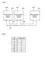
- Figure 3 is a conversion table illustrating conversion from data symbols to signal levels (mapping values), in which 3-bit data symbols are mapped to any of eight signal levels, "-7", “-5”, “-3”, “-1", “+1”, “+3”, “+5", and "+7".
- the signal that has been passed through the digital filter 115 is converted into an analog signal by the D/A converter 116, and the analog signal is passed through the low-pass filter 117, whereby a signal within a band that is slightly larger than half of the symbol rate is obtained, and a signal having no interference between adjacent codes is obtained at readout timing. Thereby, data transmission in the finite band can be carried out. Then, the driver 118 amplifies the signal intensity of this signal, and outputs the signal to the transmission path 130.
- the signal so transmitted is received by the reception unit 120.
- the receiver 121 receives the signal, and the low-pass filter 122 removes noises outside the signal band. Then, the A/D converter 123 converts the signal into digital data, and the digital data is passed through the digital filter 124.
- the digital filter 124 has roll-off characteristics in combination with the digital filter 115 of the transmission unit 110, and it converts the digital data into a signal that can be received without being affected by interference between adjacent codes, at appropriate timing.
- the evaluation unit 125 decodes the data symbols on the basis of the signal level evaluation values which are stored in the evaluation level holding unit 127.
- the clock reproduction unit 126 reproduces a clock from the received data, and establishes synchronization when decoding the data symbols. Ordinary data transmission is carried out as described above.
- Figure 5 is a diagram illustrating the first initialization pattern signal.
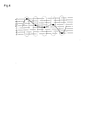
- Figure 6 is a diagram illustrating an example of a signal to be used for initialization.
- a signal to be used for initialization includes signal components as follows: a first initialization pattern signal including a frequency component equal to 1/2 of the symbol rate, in which a maximum amplitude level and a minimum amplitude level appear alternately (portion A shown in figures 5 and 6); a signal for recognizing the start of a second initialization pattern signal, which has a maximum amplitude level (portion B shown in figure 6); and a second initialization pattern signal in which all signal levels appear in an arrangement that is predetermined by the transmission unit 110 and the reception unit 120 (portion C shown in figure 6).
- the first initialization pattern signal is generated by the first initialization pattern generator 112.
- the signal for recognizing the start of the second initialization pattern signal, and the second initialization pattern signal are generated by the second initialization pattern generator 113.
- Figure 6 shows an example in which a portion of a predetermined arrangement of signal levels in the second initialization pattern signal is "+5", "+1", “-5”, “-1", “+3”, “-3”, “+5", "-7".
- This evaluation level setting pattern signal is desired to be a signal such as a PN pattern, in which all of the signal levels are evenly included, and various patterns appear.
- the transmission data controller 129 outputs, to the selector 114, a transmission data control signal indicating transmission of any of the signal from the data mapping unit 111, the first initialization pattern signal, and the second initialization pattern signal, on the basis of the output from the synchronization/initialization pattern detector 128. Then, the selector selects a signal to be transmitted, on the basis of the transmission data control signal.
- Figure 7 is a flowchart for explaining the operation of the ring-shaped network.
- a ring-shaped network comprising three stages of data transmission apparatuses 100a to 100c will be described.
- the transmission unit 110a of the first data transmission apparatus 100a transmits the first initialization pattern signal. That is, the selector 114a selects the first initialization pattern signal generated by the first initialization pattern generator 112a, and inputs this signal to the digital filter 115a. Then, the first initialization pattern signal is output to the transmission path 130a in like manner as the ordinary data transmission (step S201).
- the first initialization pattern signal so transmitted is received by the reception unit 120b of the second data transmission apparatus 100b.
- the clock reproduction unit 126b performs clock reproduction.
- a synchronization detection signal is output to the transmission data controller 129b.
- the transmission data control unit 129b outputs a transmission data control signal instructing transmission of the first initialization pattern signal, to the selector 114b of the transmission unit 110b (step S202).
- the transmission unit 110b transmits the first initialization pattern signal. That is, the selector 114b selects the first initialization pattern signal generated by the first initialization pattern generator 112b, and inputs this signal to the digital filter 115b. Then, the first initialization pattern signal is output to the transmission path 130b in like manner as the ordinary data transmission (step S203).
- the first initialization pattern signal so transmitted is received by the reception unit 120c of the third data transmission apparatus 100c.
- the reception unit 120c receives the first initialization pattern signal
- the clock reproduction unit 126c performs clock reproduction
- the synchronization/initialization pattern detector 128c detects that synchronization is established.
- the transmission data control unit 129c outputs a transmission data control signal instructing transmission of the first initialization pattern signal, to the selector 114c of the transmission unit 110c (step S204).
- the transmission unit 110c transmits the first initialization pattern signal. That is, the selector 114c selects the first initialization pattern signal generated by the first initialization pattern generator 112c, and inputs this signal to the digital filter 115c. Then, the first initialization pattern signal is output to the transmission path 130c in like manner as the ordinary data transmission (step S205).
- the first initialization pattern signal so transmitted is received by the reception unit 120a of the first data transmission apparatus 100a.
- the reception unit 120a receives the first initialization pattern signal
- the clock reproduction unit 126a reproduces a clock
- the synchronization/initialization pattern detector 128a detects that synchronization is established.
- the transmission data control unit 129a outputs a transmission data control signal instructing transmission of the second initialization pattern signal, to the selector 114a of the transmission unit 110a (step S206).
- the selector 114a selects, as a transmission signal, the second initialization pattern signal generated by the second initialization pattern generator 113a, and inputs this signal to the digital filter 115a. Then, the second initialization pattern signal and the signal for recognizing the start of the second initialization pattern signal are output to the transmission path 130a in like manner as for the first initialization pattern signal (step S207).
- the second initialization pattern signal so transmitted is received by the reception unit 120b of the second data transmission apparatus 100b.
- the transmission data controller 129b outputs a transmission data control signal instructing transmission of the second initialization pattern signal, to the selector 114b of the transmission unit 110b (step S209).
- the evaluation level holding unit 127b When the reception unit 120b receives the signal for recognizing the start of the second initialization pattern signal and, further, the second initialization pattern signal, the evaluation level holding unit 127b performs threshold evaluation for the signal levels to set evaluation levels to be used when decoding the signal levels to the data symbols.
- the evaluation level holding unit 127b detects the voltage values of the respective signal levels included in the second initialization pattern signal. That is, the voltage values of the respective signal levels "+7", “+5", “+3”, “+1", “-7”, “-5”, “-3”, and “-1" are obtained. Then, the evaluation level holding unit 127b sets the evaluation levels for the respective signal levels on the basis of the obtained voltage values of the signal levels, and holds these evaluation levels (step S210).
- the transmission unit 110b transmits the second initialization pattern signal. That is, the selector 114b selects the second initialization pattern signal generated by the second initialization pattern generator 113b, and inputs this signal to the digital filter 115b. Then, the signal for recognizing the start of the second initialization pattern signal and the second initialization pattern signal are output to the transmission path 130b in like manner as for the first initialization pattern signal (step S211).
- the transmission data controller 129b When the reception unit 120b has received all of the signal levels of the second initialization pattern signal, and setting of the evaluation levels has been completed, the transmission data controller 129b outputs a transmission data control signal instructing transmission of the signal which is mapped in the data mapping unit 111b, to the selector 114b of the transmission unit 110b (step S212).
- the transmission unit 110b continues to output data until all of the signal levels of the second initialization pattern signal are output to the transmission path 130b (step S213).
- the second data transmission apparatus 100b When reception of the second initialization pattern signal and setting of the evaluation levels (step S212) and transmission of the second initialization pattern signal (step S213) have been completed, the second data transmission apparatus 100b is in the state where it can perform transmission/reception of data (step S214).
- the second initialization pattern signal transmitted from the second data transmission apparatus 100b is received by the reception unit 120c of the third data transmission apparatus 100c.
- the transmission data controller 129c outputs a transmission data control signal instructing transmission of the second initialization pattern signal, to the selector 114c of the transmission unit 110c (step S215).
- the evaluation level holding unit 127c sets the evaluation levels, and holds them (step S216).
- the transmission unit 110c transmits the second initialization pattern signal. That is, the selector 114c selects the second initialization pattern signal generated by the second initialization pattern signal, and inputs this signal to the digital filter 115c. Then, the transmission unit 110c outputs the signal for recognizing the start of the second initialization pattern signal, and the second initialization pattern signal to the transmission path 130c in like manner as for the first initialization pattern signal (step S217).
- the transmission data controller 129c When the reception unit 120c receives all of the signal levels of the second initialization pattern signal, and setting of the evaluation levels is completed, the transmission data controller 129c outputs a transmission data control signal instructing transmission of the signal mapped in the data mapping unit 111c, to the selector 114c of the transmission unit 110c (step S218).
- the transmission unit 110c continues to output data until all of the signal levels of the second initialization pattern signal are output to the transmission path 130c (step S219).
- the third data transmission apparatus 100c When reception of the second initialization pattern signal and setting of the evaluation levels (step S218) and transmission of the second initialization pattern signal (step S219) have been completed, the third data transmission apparatus 100c is in the state where it can perform transmission/reception of data (step S220).
- the second initialization pattern signal transmitted from the third data transmission apparatus 100c is received by the reception unit 120a of the first data transmission apparatus 100a (step S221).
- the evaluation level holding unit 127a sets the evaluation levels, and holds them (step S222).
- the transmission data controller 129a When all of the signal levels of the second initialization pattern signal have been received, and setting of the evaluation levels has been completed, the transmission data controller 129a outputs a transmission data control signal instructing transmission of the signal that is mapped in the data mapping unit 111a, to the selector 114a of the transmission unit 110a (step S223).
- the first data transmission apparatus 100a When transmission of the second initialization pattern signal (step S208) and reception of the second initialization pattern signal and setting of the evaluation levels (step S223) have been completed, the first data transmission apparatus 100a is in the state where it can perform transmission/reception of data (step S224).
- clock synchronization is established in all of the data transmission apparatuses 100a to 100c connected in the ring-shaped network, and the evaluation levels are set and stored. Thereafter, transmission data control signals instructing transmission of the signals mapped in the data mapping units 111a to 111c are input to the selectors 114a to 114c of the transmission units 110a to 110c, whereby the selectors 114a to 114c select the signals from the data mapping units 111a to 111c as transmission signals. That is, transmission/reception of data is started, and the evaluation units 125a to 125c evaluate the received data and decode the data symbols with reference to the evaluation levels stored in the evaluation level holding units 127a to 127c.
- the data transmission apparatus 100 is a data transmission apparatus connected in a ring-shaped network, and the apparatus 100 is provided with the first initialization pattern output unit 112 for outputting the first initialization pattern signal to the next-stage data transmission apparatus, the second initialization pattern generation unit 113 for outputting the second initialization pattern signal to the next-stage data transmission apparatus, and the synchronization establishment unit 126 for receiving the first initialization pattern signal outputted from the previous-stage data transmission apparatus, and performing clock reproduction to establish synchronization. Since the data transmission apparatus 100 starts transmission/reception of data after synchronization is established by the first initialization pattern signal and evaluation levels are set by the second initialization pattern signal, evaluation levels can be set after synchronization of the data transmission apparatus 100 is established.
- evaluation levels are set according to the voltage values of the respective signal levels included in the second initialization pattern signal, evaluation levels can be set in accordance with the transmission path, whereby accurate data reception can be carried out without being affected by the pattern of data symbols to be transmitted or the values of the received signal levels.
- one of the data transmission apparatuses 100 connected in the ring-shaped network is used as a master which outputs the first initialization pattern signal at turn-on of power or immediately after reset, and outputs the second initialization pattern signal by the second initialization pattern generator when synchronization is established in all of the data transmission apparatuses, while the other data transmission apparatuses 100 are used as slaves which output the first initialization pattern signal from the first initialization pattern generator when synchronization is established, and output the second initialization pattern signal from the second initialization pattern generator on receipt of the beginning of the second initialization pattern signal, whereby the ring-shaped network can be initialized. Furthermore, since the slave can transmit the second initialization pattern signal to the next-stage data transmission apparatus upon receipt of the beginning of the second initialization pattern signal, setting of the evaluation levels and initialization of the ring-shaped network can be carried out more speedily.
- the first initialization pattern signal outputted from the first data transmission apparatus 100a as a master is received by the second data transmission apparatus 100b as a slave to establish synchronization.
- the second data transmission apparatus 100b outputs the first initialization pattern signal to the n-th data transmission apparatus 100n in the next stage.
- the first data transmission apparatus 100a outputs the second initialization pattern signal to the second data transmission apparatus 100b
- the second data transmission apparatus 100b receives the second initialization pattern signal to set evaluation levels, and outputs the second initialization pattern signal to the n-th data transmission apparatus 100n in the next stage.
- transmission/ reception of data is started.
- evaluation levels can be set. Further, since evaluation levels are set according to the voltage values of the respective signal levels included in the second initialization pattern signal, evaluation levels can be set in accordance with the transmission path, whereby accurate data reception can be carried out without being affected by the pattern of data symbols to be transmitted, and the values of the received signal levels.
- the first initialization pattern signal is a signal in which a maximum amplitude level and a minimum amplitude level appear alternately, clock synchronization can be established utilizing the amplitude of the first initialization pattern signal received.
- the second initialization pattern signal is a signal in which all of the signal levels appear in an arrangement that is predetermined by the transmission unit 110 and the reception unit 120, all of the signal levels can be obtained without scrambling the second initialization pattern signal.
- 3-bit data are mapped to any of eight signal levels "-7", “-5", “-3”, “-1”, “+1”, “+3”, “+5", and "+7” according to their combinations by the data mapping unit 111 of the data transmission apparatus 100.
- the present invention is not restricted to the above-described 8-value transmission, and arbitrary multi-valued transmission may be carried out.
- differential mapping in which mapping of data to be transmitted is carried out according to the signal level that is mapped last time, may be employed.
- evaluation of the signal level is carried out on the basis of the difference between the signal level that is just received by the reception unit 120 and the signal level that is received last time, and the decoding is carried out.
- the same effects as described above can be achieved by holding the evaluation levels based on the differences in the signal levels with the evaluation level holding unit.
- the data transmission apparatus transmits an initialization pattern signal at turn-on of power or immediately after reset, and performs establishment of synchronization and setting of evaluation levels on receipt of the initialization pattern signal. Therefore, evaluation levels can be set in accordance with the transmission path, and establishment of synchronization and setting of evaluation levels can be carried out also in a ring-shaped network constituted by plural data transmission apparatuses.
Landscapes
- Engineering & Computer Science (AREA)
- Computer Networks & Wireless Communication (AREA)
- Signal Processing (AREA)
- Power Engineering (AREA)
- Physics & Mathematics (AREA)
- Spectroscopy & Molecular Physics (AREA)
- Small-Scale Networks (AREA)
- Dc Digital Transmission (AREA)
- Synchronisation In Digital Transmission Systems (AREA)
- Communication Control (AREA)
- Radar Systems Or Details Thereof (AREA)
- Transmitters (AREA)
- Lock And Its Accessories (AREA)
Applications Claiming Priority (3)
| Application Number | Priority Date | Filing Date | Title |
|---|---|---|---|
| JP2000305821 | 2000-10-05 | ||
| JP2000305821 | 2000-10-05 | ||
| PCT/JP2001/008789 WO2002030078A1 (fr) | 2000-10-05 | 2001-10-05 | Procede d'initialisation et emetteur de donnees |
Publications (3)
| Publication Number | Publication Date |
|---|---|
| EP1330085A1 true EP1330085A1 (fr) | 2003-07-23 |
| EP1330085A4 EP1330085A4 (fr) | 2004-10-13 |
| EP1330085B1 EP1330085B1 (fr) | 2006-04-12 |
Family
ID=18786614
Family Applications (1)
| Application Number | Title | Priority Date | Filing Date |
|---|---|---|---|
| EP01974704A Expired - Lifetime EP1330085B1 (fr) | 2000-10-05 | 2001-10-05 | Procede d'initialisation et emetteur de donnees |
Country Status (7)
| Country | Link |
|---|---|
| US (2) | US7012936B2 (fr) |
| EP (1) | EP1330085B1 (fr) |
| JP (2) | JP3535868B2 (fr) |
| CN (1) | CN1221112C (fr) |
| AT (1) | ATE323366T1 (fr) |
| DE (1) | DE60118767T2 (fr) |
| WO (2) | WO2002030078A1 (fr) |
Cited By (3)
| Publication number | Priority date | Publication date | Assignee | Title |
|---|---|---|---|---|
| EP1524818A3 (fr) * | 2003-10-16 | 2005-12-21 | Matsushita Electric Industrial Co., Ltd. | Dispositif et système pour transmission des données, et méthode d'initialisation correspondant |
| EP1484878A3 (fr) * | 2003-06-02 | 2006-10-25 | Matsushita Electric Industrial Co., Ltd. | Procédé de réception de données, dispositif de réception de données et système de transmission de données |
| CN110089081A (zh) * | 2016-12-16 | 2019-08-02 | 松下知识产权经营株式会社 | 编码方法、解码方法、传输方法、解码设备、编码设备、传输设备 |
Families Citing this family (18)
| Publication number | Priority date | Publication date | Assignee | Title |
|---|---|---|---|---|
| US7280549B2 (en) * | 2001-07-09 | 2007-10-09 | Micron Technology, Inc. | High speed ring/bus |
| US20060155816A1 (en) * | 2002-12-25 | 2006-07-13 | Toshitomo Umei | Data transmission system and data transmission device |
| US20050265262A1 (en) * | 2002-12-26 | 2005-12-01 | Yuji Mizuguchi | Data transmission device, data transmission system, and method |
| WO2005001611A2 (fr) | 2003-05-30 | 2005-01-06 | Privaris, Inc. | Systeme et procedes permettant d'attribuer et d'utiliser des privileges de services d'abonnement a des contenus medias |
| CA2457174A1 (fr) * | 2003-07-30 | 2005-01-30 | Matsushita Electric Industrial Co., Ltd. | Systeme et appareils de transmission de donnees |
| JP4340759B2 (ja) * | 2003-09-10 | 2009-10-07 | 独立行政法人産業技術総合研究所 | デジタルデータ伝送装置 |
| JP2005150970A (ja) * | 2003-11-12 | 2005-06-09 | Matsushita Electric Ind Co Ltd | データ受信装置、データ送信装置、データ送受信装置、およびデータ伝送システム |
| US7657849B2 (en) | 2005-12-23 | 2010-02-02 | Apple Inc. | Unlocking a device by performing gestures on an unlock image |
| KR101366092B1 (ko) * | 2006-10-13 | 2014-02-21 | 삼성전자주식회사 | 다시점 영상의 부호화, 복호화 방법 및 장치 |
| KR20250099420A (ko) * | 2007-09-24 | 2025-07-01 | 애플 인크. | 전자 장치 내의 내장형 인증 시스템들 |
| CN101145851B (zh) * | 2007-10-17 | 2012-04-18 | 中兴通讯股份有限公司 | 优化调整接收机判决电平的装置和方法 |
| US8528072B2 (en) | 2010-07-23 | 2013-09-03 | Apple Inc. | Method, apparatus and system for access mode control of a device |
| WO2012157722A1 (fr) | 2011-05-18 | 2012-11-22 | シャープ株式会社 | Dispositif d'affichage à cristaux liquides |
| JP5842116B2 (ja) * | 2012-04-19 | 2016-01-13 | パナソニックIpマネジメント株式会社 | 多値信号伝送システム |
| WO2013157196A1 (fr) | 2012-04-19 | 2013-10-24 | パナソニック株式会社 | Système d'envoi de signal multi-niveau |
| EP2850510A2 (fr) | 2012-05-18 | 2015-03-25 | Apple Inc. | Dispositif, procédé et interface d'utilisateur graphique pour manipuler des interfaces d'utilisateur reposant sur des entrées de capteur d'empreintes digitales |
| EP3802599B1 (fr) | 2018-06-03 | 2023-12-20 | LamKap Bio beta AG | Anticorps bispécifiques dirigés contre ceacam5 et cd47 |
| CN112166582B (zh) * | 2018-06-04 | 2025-02-25 | 索尼公司 | 发送设备、发送方法、接收设备和接收方法 |
Family Cites Families (42)
| Publication number | Priority date | Publication date | Assignee | Title |
|---|---|---|---|---|
| US4028667A (en) | 1975-12-22 | 1977-06-07 | International Business Machines Corporation | Asynchronous, hierarchical loop communication system with independent local station control of access to inbound time portions without central control |
| US4083005A (en) | 1976-11-01 | 1978-04-04 | Burroughs Corporation | Three-level serial digital data communication system |
| JPS5915582B2 (ja) | 1978-09-08 | 1984-04-10 | 沖電気工業株式会社 | デイジタル位相同期方式 |
| FR2535557B1 (fr) | 1982-11-03 | 1987-08-21 | Electricite De France | Procede et installation de transmission de donnees numeriques |
| DE3471219D1 (en) | 1983-05-31 | 1988-06-16 | Oesterr Forsch Seibersdorf | Method and device for the transfer of data in a data loop |
| JPS63110840A (ja) | 1986-10-29 | 1988-05-16 | Nec Corp | 同期検出回路 |
| US4924492A (en) | 1988-03-22 | 1990-05-08 | American Telephone And Telegraph Company | Method and apparatus for wideband transmission of digital signals between, for example, a telephone central office and customer premises |
| JP2664249B2 (ja) | 1989-03-13 | 1997-10-15 | 株式会社日立製作所 | タイミング抽出回路,それを利用した通信システム及びタイミング抽出方法並びに通信装置 |
| US4982185A (en) | 1989-05-17 | 1991-01-01 | Blh Electronics, Inc. | System for synchronous measurement in a digital computer network |
| US5052021A (en) * | 1989-05-19 | 1991-09-24 | Kabushiki Kaisha Toshiba | Digital signal decoding circuit and decoding method |
| JPH03195144A (ja) | 1989-12-22 | 1991-08-26 | Mitsubishi Electric Corp | リング型ローカルエリアネットワークのクロック同期装置 |
| GB9007600D0 (en) | 1990-04-04 | 1990-05-30 | Hunting Communication Tech | Ring communication system |
| GB2243733A (en) * | 1990-05-01 | 1991-11-06 | Orbitel Mobile Communications | Gain control based on average amplitude of i/p signal |
| AT401838B (de) | 1990-06-01 | 1996-12-27 | Schrack Telecom | Verfahren zur aufbereitung von signalen für die signalübertragung im basisband |
| US5303265A (en) | 1990-06-29 | 1994-04-12 | Digital Equipment Corporation | Frequency independent encoding technique and apparatus for digital communications |
| GB2250898A (en) | 1990-12-12 | 1992-06-17 | Stc Plc | Line coding scheme. |
| EP0530342B1 (fr) * | 1991-03-20 | 1997-12-29 | British Broadcasting Corporation | Compression sonore |
| US5206857A (en) | 1991-04-29 | 1993-04-27 | At&T Bell Laboratories | Apparatus and method for timing distribution over an asynchronous ring |
| JPH04352535A (ja) * | 1991-05-30 | 1992-12-07 | Nec Corp | ループ式伝送路制御方式 |
| JPH0514419A (ja) | 1991-07-04 | 1993-01-22 | Honda Motor Co Ltd | デ―タ伝送方法 |
| US5477257A (en) * | 1991-11-11 | 1995-12-19 | Matsushita Electric Industrial Co., Ltd. | Image forming method and apparatus using rotated screen with pulse width modulation |
| JP3259302B2 (ja) * | 1992-01-28 | 2002-02-25 | 株式会社日立製作所 | 出力信号復号方法および装置 |
| JPH0629987A (ja) | 1992-07-06 | 1994-02-04 | Nippon Telegr & Teleph Corp <Ntt> | クロック同期方式 |
| DE69419055T2 (de) * | 1993-03-26 | 1999-12-23 | Sony Corp., Tokio/Tokyo | Vorrichtung zum Erzeugen eines Synchronisierungssignals |
| US5517481A (en) * | 1993-07-02 | 1996-05-14 | Sony Corporation | Optical recording and reproducing apparatus wherein data is recorded by stepwise shifting the edge position of each pit |
| JP3756948B2 (ja) | 1993-09-09 | 2006-03-22 | ブリテイッシュ・テレコミュニケーションズ・パブリック・リミテッド・カンパニー | 量子暗号を使用するキー配送システムおよび方法 |
| FR2723276B1 (fr) | 1994-08-01 | 1996-10-04 | Lewiner Jacques | Procede et dispositif de decodage d'un signal electrique multivalent et ensemble de reception comportant un tel disposiif de decodage |
| US5812594A (en) | 1994-10-14 | 1998-09-22 | Rakib; Selim | Method and apparatus for implementing carrierless amplitude/phase encoding in a network |
| JPH08163162A (ja) * | 1994-12-08 | 1996-06-21 | Mitsubishi Electric Corp | ループ式データ伝送装置 |
| US6421323B1 (en) | 1994-12-23 | 2002-07-16 | Applied Digital Access, Inc. | Method and apparatus for analyzing events in a telecommunications system |
| JPH08317012A (ja) | 1995-05-23 | 1996-11-29 | Toshiba Corp | ディジタル復調器 |
| JP2638582B2 (ja) | 1995-10-30 | 1997-08-06 | 株式会社日立製作所 | タイミング抽出回路、それを利用した通信システム及びタイミング抽出方法並びに通信装置 |
| JPH09186726A (ja) | 1995-10-30 | 1997-07-15 | Casio Comput Co Ltd | 多値信号復調装置及び多値信号復調方法 |
| US5825243A (en) | 1995-10-30 | 1998-10-20 | Casio Computer Co., Ltd. | Apparatus and method for demodulating multi-level signal |
| JPH09205466A (ja) * | 1996-01-29 | 1997-08-05 | Kokusai Electric Co Ltd | シンボル判定装置 |
| US6157680A (en) | 1997-03-05 | 2000-12-05 | Paradyne Corporation | Audio distortion canceler method and apparatus |
| JP3564654B2 (ja) | 1998-07-30 | 2004-09-15 | 日本電気エンジニアリング株式会社 | 標本化クロック再生回路 |
| JP2000165457A (ja) | 1998-11-25 | 2000-06-16 | Matsushita Electric Ind Co Ltd | 多値信号増幅用agc増幅器 |
| JP2000349605A (ja) | 1999-03-26 | 2000-12-15 | Matsushita Electric Ind Co Ltd | 識別回路 |
| TW445718B (en) | 1999-03-26 | 2001-07-11 | Matsushita Electric Industrial Co Ltd | Discriminator |
| US6545532B1 (en) | 1999-09-08 | 2003-04-08 | Atmel Corporation | Timing recovery circuit in a QAM demodulator |
| US7206362B2 (en) | 2001-02-08 | 2007-04-17 | International Business Machines Corporation | Binary data transmission on a single information channel |
-
2001
- 2001-10-05 JP JP2002533566A patent/JP3535868B2/ja not_active Expired - Fee Related
- 2001-10-05 JP JP2002533567A patent/JP3535869B2/ja not_active Expired - Fee Related
- 2001-10-05 US US10/398,452 patent/US7012936B2/en not_active Expired - Fee Related
- 2001-10-05 CN CN01816783.7A patent/CN1221112C/zh not_active Expired - Fee Related
- 2001-10-05 US US10/398,451 patent/US7042965B2/en not_active Expired - Fee Related
- 2001-10-05 WO PCT/JP2001/008789 patent/WO2002030078A1/fr not_active Ceased
- 2001-10-05 AT AT01974704T patent/ATE323366T1/de not_active IP Right Cessation
- 2001-10-05 WO PCT/JP2001/008786 patent/WO2002030077A1/fr not_active Ceased
- 2001-10-05 EP EP01974704A patent/EP1330085B1/fr not_active Expired - Lifetime
- 2001-10-05 DE DE60118767T patent/DE60118767T2/de not_active Expired - Lifetime
Non-Patent Citations (2)
| Title |
|---|
| No further relevant documents disclosed * |
| See also references of WO0230078A1 * |
Cited By (3)
| Publication number | Priority date | Publication date | Assignee | Title |
|---|---|---|---|---|
| EP1484878A3 (fr) * | 2003-06-02 | 2006-10-25 | Matsushita Electric Industrial Co., Ltd. | Procédé de réception de données, dispositif de réception de données et système de transmission de données |
| EP1524818A3 (fr) * | 2003-10-16 | 2005-12-21 | Matsushita Electric Industrial Co., Ltd. | Dispositif et système pour transmission des données, et méthode d'initialisation correspondant |
| CN110089081A (zh) * | 2016-12-16 | 2019-08-02 | 松下知识产权经营株式会社 | 编码方法、解码方法、传输方法、解码设备、编码设备、传输设备 |
Also Published As
| Publication number | Publication date |
|---|---|
| EP1330085A4 (fr) | 2004-10-13 |
| JP3535868B2 (ja) | 2004-06-07 |
| WO2002030077A1 (fr) | 2002-04-11 |
| US20040013214A1 (en) | 2004-01-22 |
| JPWO2002030077A1 (ja) | 2004-02-19 |
| CN1221112C (zh) | 2005-09-28 |
| JP3535869B2 (ja) | 2004-06-07 |
| US20040042542A1 (en) | 2004-03-04 |
| DE60118767T2 (de) | 2007-02-15 |
| CN1468484A (zh) | 2004-01-14 |
| US7012936B2 (en) | 2006-03-14 |
| JPWO2002030078A1 (ja) | 2004-02-19 |
| EP1330085B1 (fr) | 2006-04-12 |
| WO2002030078A1 (fr) | 2002-04-11 |
| US7042965B2 (en) | 2006-05-09 |
| DE60118767D1 (de) | 2006-05-24 |
| ATE323366T1 (de) | 2006-04-15 |
Similar Documents
| Publication | Publication Date | Title |
|---|---|---|
| EP1330085B1 (fr) | Procede d'initialisation et emetteur de donnees | |
| US7190728B2 (en) | Digital data transmitter, transmission line encoding method, and decoding method | |
| US7218678B2 (en) | Digital data transmitter | |
| FI89436B (fi) | Synkronisationsregenerering i telekommunikationssystem | |
| US5898734A (en) | Symbol determining method and apparatus | |
| EP1330086A1 (fr) | Reseau local en anneau et emetteur de donnees | |
| US20060155816A1 (en) | Data transmission system and data transmission device | |
| EP1280310B1 (fr) | Structure de signal et embrouillage pour la transmission multiporteuse | |
| JP3522745B2 (ja) | 伝送路符号化方法、および復号方法 | |
| JP2003528542A (ja) | データネットワークにおいて複数の信号フォーマットのための入力利得を調整するための装置および方法 | |
| US7221294B1 (en) | Multispeed communications device | |
| CN110740105A (zh) | 信号处理方法和装置 | |
| TWI869261B (zh) | 降低電源訊號線雜訊對解碼影響的方法以及使用其之解碼電路 | |
| US6839006B1 (en) | Communication device | |
| JP7836575B2 (ja) | 受信装置 | |
| US20060034388A1 (en) | Data sending device, data receiving device, transmission path encoding method, and decoding method | |
| WO2001099365A1 (fr) | Systeme et procede de transmission a debit binaire eleve | |
| TW202543246A (zh) | 降低電源訊號線雜訊對解碼影響的方法以及使用其之解碼電路 | |
| WO1997027694A1 (fr) | Transmission numerique sur des liaisons optiques paralleles | |
| JP2005150970A (ja) | データ受信装置、データ送信装置、データ送受信装置、およびデータ伝送システム |
Legal Events
| Date | Code | Title | Description |
|---|---|---|---|
| PUAI | Public reference made under article 153(3) epc to a published international application that has entered the european phase |
Free format text: ORIGINAL CODE: 0009012 |
|
| 17P | Request for examination filed |
Effective date: 20030502 |
|
| AK | Designated contracting states |
Designated state(s): AT BE CH CY DE DK ES FI FR GB GR IE IT LI LU MC NL PT SE TR |
|
| RIN1 | Information on inventor provided before grant (corrected) |
Inventor name: MIZUGUCHI, YUJI Inventor name: TAKAHIRA, YUTAKA Inventor name: KATTA, NOBORU Inventor name: KAWADA, HIROTSUGU Inventor name: SAKAI, TAKAHISA Inventor name: YASUI, NOBUHIKO Inventor name: KUROSAKI, TOSHIHIKO |
|
| A4 | Supplementary search report drawn up and despatched |
Effective date: 20040901 |
|
| 17Q | First examination report despatched |
Effective date: 20041220 |
|
| GRAP | Despatch of communication of intention to grant a patent |
Free format text: ORIGINAL CODE: EPIDOSNIGR1 |
|
| GRAS | Grant fee paid |
Free format text: ORIGINAL CODE: EPIDOSNIGR3 |
|
| GRAA | (expected) grant |
Free format text: ORIGINAL CODE: 0009210 |
|
| AK | Designated contracting states |
Kind code of ref document: B1 Designated state(s): AT BE CH CY DE DK ES FI FR GB GR IE IT LI LU MC NL PT SE TR |
|
| PG25 | Lapsed in a contracting state [announced via postgrant information from national office to epo] |
Ref country code: AT Free format text: LAPSE BECAUSE OF FAILURE TO SUBMIT A TRANSLATION OF THE DESCRIPTION OR TO PAY THE FEE WITHIN THE PRESCRIBED TIME-LIMIT Effective date: 20060412 Ref country code: BE Free format text: LAPSE BECAUSE OF FAILURE TO SUBMIT A TRANSLATION OF THE DESCRIPTION OR TO PAY THE FEE WITHIN THE PRESCRIBED TIME-LIMIT Effective date: 20060412 Ref country code: NL Free format text: LAPSE BECAUSE OF FAILURE TO SUBMIT A TRANSLATION OF THE DESCRIPTION OR TO PAY THE FEE WITHIN THE PRESCRIBED TIME-LIMIT Effective date: 20060412 Ref country code: FI Free format text: LAPSE BECAUSE OF FAILURE TO SUBMIT A TRANSLATION OF THE DESCRIPTION OR TO PAY THE FEE WITHIN THE PRESCRIBED TIME-LIMIT Effective date: 20060412 Ref country code: LI Free format text: LAPSE BECAUSE OF FAILURE TO SUBMIT A TRANSLATION OF THE DESCRIPTION OR TO PAY THE FEE WITHIN THE PRESCRIBED TIME-LIMIT Effective date: 20060412 Ref country code: CH Free format text: LAPSE BECAUSE OF FAILURE TO SUBMIT A TRANSLATION OF THE DESCRIPTION OR TO PAY THE FEE WITHIN THE PRESCRIBED TIME-LIMIT Effective date: 20060412 Ref country code: IT Free format text: LAPSE BECAUSE OF FAILURE TO SUBMIT A TRANSLATION OF THE DESCRIPTION OR TO PAY THE FEE WITHIN THE PRESCRIBED TIME-LIMIT;WARNING: LAPSES OF ITALIAN PATENTS WITH EFFECTIVE DATE BEFORE 2007 MAY HAVE OCCURRED AT ANY TIME BEFORE 2007. THE CORRECT EFFECTIVE DATE MAY BE DIFFERENT FROM THE ONE RECORDED. Effective date: 20060412 |
|
| REG | Reference to a national code |
Ref country code: GB Ref legal event code: FG4D |
|
| REG | Reference to a national code |
Ref country code: CH Ref legal event code: EP |
|
| REF | Corresponds to: |
Ref document number: 60118767 Country of ref document: DE Date of ref document: 20060524 Kind code of ref document: P |
|
| REG | Reference to a national code |
Ref country code: IE Ref legal event code: FG4D |
|
| PG25 | Lapsed in a contracting state [announced via postgrant information from national office to epo] |
Ref country code: SE Free format text: LAPSE BECAUSE OF FAILURE TO SUBMIT A TRANSLATION OF THE DESCRIPTION OR TO PAY THE FEE WITHIN THE PRESCRIBED TIME-LIMIT Effective date: 20060712 Ref country code: DK Free format text: LAPSE BECAUSE OF FAILURE TO SUBMIT A TRANSLATION OF THE DESCRIPTION OR TO PAY THE FEE WITHIN THE PRESCRIBED TIME-LIMIT Effective date: 20060712 |
|
| PG25 | Lapsed in a contracting state [announced via postgrant information from national office to epo] |
Ref country code: ES Free format text: LAPSE BECAUSE OF FAILURE TO SUBMIT A TRANSLATION OF THE DESCRIPTION OR TO PAY THE FEE WITHIN THE PRESCRIBED TIME-LIMIT Effective date: 20060723 |
|
| PG25 | Lapsed in a contracting state [announced via postgrant information from national office to epo] |
Ref country code: PT Free format text: LAPSE BECAUSE OF FAILURE TO SUBMIT A TRANSLATION OF THE DESCRIPTION OR TO PAY THE FEE WITHIN THE PRESCRIBED TIME-LIMIT Effective date: 20060912 |
|
| NLV1 | Nl: lapsed or annulled due to failure to fulfill the requirements of art. 29p and 29m of the patents act | ||
| PG25 | Lapsed in a contracting state [announced via postgrant information from national office to epo] |
Ref country code: IE Free format text: LAPSE BECAUSE OF NON-PAYMENT OF DUE FEES Effective date: 20061005 |
|
| REG | Reference to a national code |
Ref country code: CH Ref legal event code: PL |
|
| PG25 | Lapsed in a contracting state [announced via postgrant information from national office to epo] |
Ref country code: MC Free format text: LAPSE BECAUSE OF NON-PAYMENT OF DUE FEES Effective date: 20061031 |
|
| ET | Fr: translation filed | ||
| PLBE | No opposition filed within time limit |
Free format text: ORIGINAL CODE: 0009261 |
|
| STAA | Information on the status of an ep patent application or granted ep patent |
Free format text: STATUS: NO OPPOSITION FILED WITHIN TIME LIMIT |
|
| 26N | No opposition filed |
Effective date: 20070115 |
|
| PG25 | Lapsed in a contracting state [announced via postgrant information from national office to epo] |
Ref country code: GR Free format text: LAPSE BECAUSE OF FAILURE TO SUBMIT A TRANSLATION OF THE DESCRIPTION OR TO PAY THE FEE WITHIN THE PRESCRIBED TIME-LIMIT Effective date: 20060713 |
|
| PG25 | Lapsed in a contracting state [announced via postgrant information from national office to epo] |
Ref country code: TR Free format text: LAPSE BECAUSE OF FAILURE TO SUBMIT A TRANSLATION OF THE DESCRIPTION OR TO PAY THE FEE WITHIN THE PRESCRIBED TIME-LIMIT Effective date: 20060412 Ref country code: LU Free format text: LAPSE BECAUSE OF NON-PAYMENT OF DUE FEES Effective date: 20061005 |
|
| PG25 | Lapsed in a contracting state [announced via postgrant information from national office to epo] |
Ref country code: CY Free format text: LAPSE BECAUSE OF FAILURE TO SUBMIT A TRANSLATION OF THE DESCRIPTION OR TO PAY THE FEE WITHIN THE PRESCRIBED TIME-LIMIT Effective date: 20060412 |
|
| PGFP | Annual fee paid to national office [announced via postgrant information from national office to epo] |
Ref country code: GB Payment date: 20090930 Year of fee payment: 9 |
|
| REG | Reference to a national code |
Ref country code: GB Ref legal event code: 746 Effective date: 20091221 |
|
| PGFP | Annual fee paid to national office [announced via postgrant information from national office to epo] |
Ref country code: DE Payment date: 20091001 Year of fee payment: 9 |
|
| PGFP | Annual fee paid to national office [announced via postgrant information from national office to epo] |
Ref country code: FR Payment date: 20091029 Year of fee payment: 9 |
|
| GBPC | Gb: european patent ceased through non-payment of renewal fee |
Effective date: 20101005 |
|
| PG25 | Lapsed in a contracting state [announced via postgrant information from national office to epo] |
Ref country code: FR Free format text: LAPSE BECAUSE OF NON-PAYMENT OF DUE FEES Effective date: 20101102 |
|
| REG | Reference to a national code |
Ref country code: FR Ref legal event code: ST Effective date: 20110630 |
|
| PG25 | Lapsed in a contracting state [announced via postgrant information from national office to epo] |
Ref country code: GB Free format text: LAPSE BECAUSE OF NON-PAYMENT OF DUE FEES Effective date: 20101005 |
|
| REG | Reference to a national code |
Ref country code: DE Ref legal event code: R119 Ref document number: 60118767 Country of ref document: DE Effective date: 20110502 |
|
| PG25 | Lapsed in a contracting state [announced via postgrant information from national office to epo] |
Ref country code: DE Free format text: LAPSE BECAUSE OF NON-PAYMENT OF DUE FEES Effective date: 20110502 |