EP1331719A2 - Herstellung einer segmentierten elektrischen Maschine - Google Patents
Herstellung einer segmentierten elektrischen Maschine Download PDFInfo
- Publication number
- EP1331719A2 EP1331719A2 EP03001589A EP03001589A EP1331719A2 EP 1331719 A2 EP1331719 A2 EP 1331719A2 EP 03001589 A EP03001589 A EP 03001589A EP 03001589 A EP03001589 A EP 03001589A EP 1331719 A2 EP1331719 A2 EP 1331719A2
- Authority
- EP
- European Patent Office
- Prior art keywords
- subassembly
- wire
- pallet
- casing
- stator
- Prior art date
- Legal status (The legal status is an assumption and is not a legal conclusion. Google has not performed a legal analysis and makes no representation as to the accuracy of the status listed.)
- Withdrawn
Links
Images


Classifications
-
- H—ELECTRICITY
- H02—GENERATION; CONVERSION OR DISTRIBUTION OF ELECTRIC POWER
- H02K—DYNAMO-ELECTRIC MACHINES
- H02K15/00—Processes or apparatus specially adapted for manufacturing, assembling, maintaining or repairing of dynamo-electric machines
- H02K15/08—Forming windings by laying conductors into or around core parts
- H02K15/095—Forming windings by laying conductors into or around core parts by laying conductors around salient poles
-
- H—ELECTRICITY
- H02—GENERATION; CONVERSION OR DISTRIBUTION OF ELECTRIC POWER
- H02K—DYNAMO-ELECTRIC MACHINES
- H02K15/00—Processes or apparatus specially adapted for manufacturing, assembling, maintaining or repairing of dynamo-electric machines
- H02K15/02—Processes or apparatus specially adapted for manufacturing, assembling, maintaining or repairing of dynamo-electric machines of stator or rotor bodies
- H02K15/021—Magnetic cores
- H02K15/022—Magnetic cores with salient poles
-
- Y—GENERAL TAGGING OF NEW TECHNOLOGICAL DEVELOPMENTS; GENERAL TAGGING OF CROSS-SECTIONAL TECHNOLOGIES SPANNING OVER SEVERAL SECTIONS OF THE IPC; TECHNICAL SUBJECTS COVERED BY FORMER USPC CROSS-REFERENCE ART COLLECTIONS [XRACs] AND DIGESTS
- Y10—TECHNICAL SUBJECTS COVERED BY FORMER USPC
- Y10T—TECHNICAL SUBJECTS COVERED BY FORMER US CLASSIFICATION
- Y10T29/00—Metal working
- Y10T29/49—Method of mechanical manufacture
- Y10T29/49002—Electrical device making
- Y10T29/49009—Dynamoelectric machine
-
- Y—GENERAL TAGGING OF NEW TECHNOLOGICAL DEVELOPMENTS; GENERAL TAGGING OF CROSS-SECTIONAL TECHNOLOGIES SPANNING OVER SEVERAL SECTIONS OF THE IPC; TECHNICAL SUBJECTS COVERED BY FORMER USPC CROSS-REFERENCE ART COLLECTIONS [XRACs] AND DIGESTS
- Y10—TECHNICAL SUBJECTS COVERED BY FORMER USPC
- Y10T—TECHNICAL SUBJECTS COVERED BY FORMER US CLASSIFICATION
- Y10T29/00—Metal working
- Y10T29/49—Method of mechanical manufacture
- Y10T29/49002—Electrical device making
- Y10T29/4902—Electromagnet, transformer or inductor
- Y10T29/49073—Electromagnet, transformer or inductor by assembling coil and core
Definitions
- the present invention relates to improved solutions for processing dynamo-electric machine components (e.g., armatures or stators for electric motors, generators, or alternators).
- dynamo-electric machine components e.g., armatures or stators for electric motors, generators, or alternators.
- Dynamo-electric machines include a rotating cylinder called the armature in a stationary part called the stator.
- the stator is a thick-walled tube (core or yoke) that surrounds the armature, which is also called the rotor.
- the stator has windings that produce a rotating magnetic field in the space occupied by the rotor. This magnetic field interacts, for example, with current passed through windings in the armature to generate forces that turn the armature. Conversely, when the armature is rotated by an external prime mover, the stator magnetic field induces a voltage in the windings.
- the armature and stator windings are wire coils wound on ferromagnetic pieces or cores (poles). These poles, for example, in the case of a stator, extend radially inward from the inner surface of the stator core or yoke.
- the radially inward extending poles usually have rectangular cross sections that fan or extend out into what are known as pole heads or shoes. Adjacent longitudinal slots formed along the inner surface of the stator core or yoke may define the poles.
- longitudinal ferromagnetic pieces (pole cores) may be mounted on the inner surface of the stator core or yoke. Conventional joining techniques, such as dovetail joints, may be used to securely mount the pole cores.
- the dimensional tolerances of the stator and the armature, the pole configurations, and wire coil-winding properties (such as wire size, pitch, number of turns) all contribute or determine the operational characteristics of the dynamo-electric machine.
- stator wire coils are often injected or wound using automated machinery that includes a wire dispenser or needle mounted on a moving arm.
- the wire dispenser travels back and forth through the stator bore alongside a pole, dispensing wire stretches that are deposited on the pole sides and ends to form a wire coil.
- winding operations can be difficult, inconvenient or slow because of the limited geometrical access to the pole sides through the confines of a stator bore.
- the detrimental effect of the limited geometrical access for wire coil winding may be more pronounced for multiple-pole stators.
- Wire winding operations through the stator bores may be avoided by assembling stators using subassemblies, one of which has the pole sides extending out from an inner structure.
- Wire coils may be wound on such a subassembly from outside its bore using flyer-type winders that are conventionally used, for example, to wind armature coils.
- flyer-type winders that are conventionally used, for example, to wind armature coils.
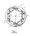
- the two references respectively show single and two-section hollow annular inner casings (e.g., casing IC, FIG. 1) made of tubular plastic material with receptacles or seats into which the pole cores (e.g., poles 70) may be installed.
- the pole cores may be installed in the seats through the hollow interior of the inner casing.
- the pole pieces may be inserted lengthwise in the seats in separated inner casing tube sections that are later closed over the inserted pole pieces.
- the inner casings have slots or pockets (e.g., pockets B) alongside the pole seats to accommodate wire coils.
- the inner casing may be fitted in an outer casing (e.g., casing OC) to assemble a stator (e.g., stator S).
- a stator e.g., stator S
- the two casings are mechanically held together, for example, by interference fit of pole portions (e.g., dovetail pins DP) in suitable slots that are fashioned in the outer casing.
- inventive methods and apparatus for the fabrication of dynamoelectric machine components from multiple parts or segments are provided.
- the inventive methods and apparatus may be used for improving the manufacturing processes used in making or assembling components from multiple part subassemblies.
- a pallet-based transportation system is provided for the fabrication of stators from multi-part inner subassemblies on which stator wire coils may be wound using flyer-type winders.
- the inner subassemblies are made from one or more plastic tube section and several stator pole pieces around which wire coils are wound. These multiple-part inner subassemblies may lack structural strength or rigidity until the final fabrication steps. Outer casings or support rings are fitted on the inner subassemblies to finalize the usable stator structure.
- the pallet for carrying multiple-part stator subassembly includes support or seating structures for holding the subassembly in an upright orientation, and fixtures for referencing the radial positions of stator poles in the subassembly.
- the support structures and the referencing fixtures are designed to hold the stator subassembly through all the fabrication stages involves in making the inner subassembly from plastic tube sections, stator poles, and wire coils.
- the seating or support structures and the radial position referencing fixtures are coaxial cylindrical structures that are disposed around an aperture in the pallet.
- the support structures have an inner ledge surface on which a stator subassembly can be seated in an upright orientation.
- the referencing fixtures are a circular array of spaced-apart vertical slats, which abut stator pole pieces in the seated in the uprightly seated stator subassemblies.
- the referencing fixtures may be detachable.
- the support structures and the radial position referencing fixtures provide structural strength and rigidity to stator subassemblies that lack the same.
- a lift mechanism operates though the aperture in the pallet to raise seated stator subassembly to a work position in a flyer-type wire coil winder.
- the lift mechanism includes an expanding collet whose clamps operate through the spacings in the circular array of the radial position referencing vertical slats to grip and firmly hold the stator subassembly poles.
- the lift mechanism presents the firmly held poles in proper alignment for wire coil winding by a winding head in the winder.
- a specific winding head can be used for winding wire coils in pockets adjoining the presented poles.
- the specific winding head includes a flyer arm and one or more pairs of movable wire guides.
- a pair of wire guides is shaped to include sloped wire-running portions extending into wire drop surfaces for controllably placing wire turns at specific locations in pockets. This pair of wire guides may be used for depositing layered and tightly wound wire coils.
- the other pairs of wire guides are utilized direct or guide wire dispensed by the flyer over geometrical obstructions into the pocket in which the wire coil is being wound.
- Another lift mechanism is used in conjunction with the pallet for compression fitting of the stator inner subassembly in the stator outer casing.
- Another lift mechanism includes a pair of movable press blocks on opposite sides of a centering ring.
- the centering ring and one of the movable blocks are designed to sandwich and hold the stator outer casing in an upright orientation.
- the other movable block is designed to operate from below the pallet to lift and push the stator inner subassembly into the sandwiched stator outer casing.
- the centering ring has tapered bore structure to align and radially compress the inner subassembly as it is pushed into the sandwiched stator outer casing.
- the tapered bore structure includes channels or grooves to receive dovetail pins or other locking structures on the surface of the inner casing.
- the channels or grooves are designed to align and direct the received dovetail pins or other locking structures into corresponding dovetail slots in outer casing.
- the present disclosure provides solutions for uniform and reproducible manufacturing of dynamo-electric machine components.
- the disclosed solutions relate to the processing of subassemblies that include multiple parts or segments.
- the disclosed solutions include inventive features to enhance control of the dimensions of fabricated parts.
- the inventive features may be built into the subassembly structures, their transport systems, and/or the processing tools.
- the disclosed solutions may find application in manufacturing processes where it is important to maintain the integrity of the geometrical configuration of the multiple parts in a subassembly during the processing steps.
- An illustrative stator inner subassembly or casing is an annular configuration of multiple stator pole pieces that are installed in longitudinal seats or receptacles that run lengthwise along the sides of a plastic tube.
- the inner casing subassembly may, for example, be similar to those described in Becherucci et al. European patent application No. 1020975, or Taguchi et al. U.S. patent No. 4,818,911.
- the inner casing may include a single plastic tube section or include two or more joinable plastic tube sections.
- a disclosed manufacturing solution includes transport systems, which preserve the geometrical configuration of multiple parts in a stator subassembly while advancing the stator subassembly from one processing step to the next.
- the transport systems use a pallet for carrying the multiple-part stator subassembly to work positions in various processing tools.
- An embodiment of the pallet for carrying the multiple-part stator subassembly is described herein, preliminarily in the context of the fabrication of a multiple pole stator inner subassembly or casing, with reference to FIGS. 2, 3, 4a, 4b, 5a, 5b and 6.
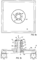
- FIGS. 2 and 3 show an exemplary pallet base 10 on which a bottom tube section 60b of a two-section inner casing tube 60 rests.
- Pallet base 10 may have a rigid plate-like construction, which can be transported on assembly line conveyor belts or rails 11 in a horizontal orientation.
- Pallet base 10 may be fabricated using, for example, a rigid plate 10a.
- Subassembly support structure 12 is disposed on plate 10a to physically support stator subassemblies in a suitable upright orientation.
- Subassembly support structure 12 may, for example, be a hollow cylindrical fixture with a tub-shaped bottom that is seated in a circular cutout in rigid plate 10a. The bore of support structure 12 is open at both ends.
- the lower bore end is open through an aperture in the tube-shaped bottom.
- Annular edge or rim portions 12' of support structure 12 are suitably shaped to physically contact and support edge portions of upright stator subassemblies.
- Edge portions 12' may, for example, be fashioned as an inner ledge in the cylindrical sides of support structure 12.
- Bottom tube section 60b can rest in an upright or vertical orientation on the inner ledge.
- Portions of stator pole pieces 70 (FIG. 4a) that may be inserted upright in the seats in bottom tube section 60b also may rest on the inner ledge.
- portions of pole shoe 72 and/or pole pins 76 of inserted pole piece 70 may rest on the inner ledge.
- support structure 12 need not contact all end surfaces of a supported stator subassembly to maintain the latter in a desired upright position.
- Annular edge portions 12' may be designed to be suitably discontinuous to accommodate various geometric aspects or features of stator subassemblies.
- support structure 12 sidewalls (and edge portions 12') may be broken as suitably spaced vertical sections or pillars,.
- the pillar heights and the inter-pillar spacings may be suitably designed to accommodate the bottom portions of wire coils wound around stator poles 70 of an uprightly seated stator inner subassembly.
- pallet 10 includes a removable fixture 13 that serves as a radial position reference for parts of the supported stator subassembly.
- Fixture 13 may, for example, have a cylindrical structure that extends upward from pallet 10 through the annulus of support structure 12 and through the bore of any supported stator subassembly.
- the tubular sides of fixture 13 may, for example, be a circular array of spaced-apart slats or strips 13'. Adjacent slats 13' in the array may be separated by a spacing or passageway 13''. Passageways 13'' provide clearance for the operation of external workpiece-handling tools (such as collet clamps 24' FIG. 6).
- Slats 13' provide radial position references for poles 70 inserted in the seats in the inner casing tubes. Slats 13' may be designed to abut portions of pole shoes 72 along the length of poles 70.
- Abutting slats 13' resist tilt, sag, or other position shifts by the inserted poles 70, and thereby help preserve the geometrical configuration of the supported stator subassembly.
- An optional circular cap 13''' that crowns upright slats 13' may be used to structurally reinforce or stabilize fixture 13.
- Fixture 13 may be releasably fastened to pallet 10 using conventional mechanical arrangements.
- FIG. 3 shows an exemplary fastening arrangement using spring-loaded ball positioner 14'. Positioner 14' is threaded in support structure 12 such that a spring-loaded fastening ball 14 is biased to center and releasably hold fixture 13 in support'structure 12.
- Fixture 13 and support structure 12 on pallet 10 may be suitably replaced or changed to correspond to the particular size or type of stator that is being manufactured.
- FIGS. 4a, 4b, 5a, 5b and 6 bottom tube section 60b resting on support structure 12 of pallet 10 (FIGS. 2 and 3) may be loaded with exemplary pole pieces 70.
- FIG. 4a schematically depicts the insertion of pole piece 70 in the seats or receptacles in bottom tube section 60b.
- FIG. 4b shows inserted pole pieces 70 in upright orientations abutting slats 13'.
- pallet 10 may be moved on belts 11 to another workstation, for example, where a top tube section 60a can be lowered over inserted pole pieces 70.
- edge portions 12' and slats 13' preserve the upright orientation and the radial positions of inserted poles 70.
- top tube section 60a may be readily lowered over them (70) and joined with bottom tube section 60b to form a single tube 60.
- FIGS. 5a, 5b, and 6 show stator inner subassembly or casing 60 with the joined tube sections.
- FIG. 6 additionally shows a workpiece gripper or collet that has been introduced in the bore of stator inner casing 60.
- collet clamps 24' move through inter-pillar passageways 13'' of fixture 13 to contact the surfaces of poles 70.
- Collet clamps 24' are shown radially biased against pole pieces 70.
- Multiple-pole stator inner casing 60 shown in FIGS. 5a and 5b may be further transported on pallet 10 to a winding station.
- wire coils may be wound in casing pockets 62 that encircle poles 70 (FIG. 6).
- a flyer-type winder may be used for the wire coil winding (e.g., winder 20' FIG. 7).
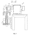
- the inventive transport systems include workpiece loading and unloading apparatus (e.g., apparatus 23). Apparatus 23 may be used to move transported stator inner casing 60 from pallet 10 to a raised work position in flyer-type winder 20'. Additional features of apparatus 23 and its operation in conjunction with winder 20' and pallet 10 are described herein, for example, with reference to FIGS. 6, 7, 8a, 8b, 9 and 10.
- Winder 20' may have a winding head 52 for depositing a wire coil around any one of poles 70 of raised inner casing 60.
- winder 20' may include several winding heads for winding wire coils around several poles simultaneously (see e.g., Becherucci et al. EP 1020975).
- Exemplary winding head 52 includes a flyer 20 and winding guide 21 mounted on a shaft 22.
- flyer 20 rotates on shaft 22 around one of poles 70 of raised casing 60 to deposit wire turns in pocket 62 adjoining the subject pole.
- winding guide 21 is suitably positioned in alignment with subject pole 70 and flyer 20, to direct wire dispensed by flyer 20 into pocket 62.
- Shaft 22 also may be used to translate flyer 20 and winding guide 21 to and fro in directions 22' and 22'' to deposit wire at different depths in pocket 62.
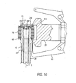
- winding guide 21 may have a suitable shape with hollow central portion or cutout abutting subject pole 70.
- the central cutout permits unhindered movement of winding guide 21 in directions 22' and 22'' over the ends of pocket 62 adjoining subject pole 70 (FIG. 10).
- shaft 22 translation may be suitably controlled to deposit wire turns in successive layers and obtain desirable stratification of the deposited wire coil.
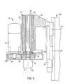
- exemplary apparatus 23 which may be used for lifting or raising inner casing 60 to the work position in winder 20', is placed underneath pallet 10 (FIG. 8a).
- Apparatus 23 includes gripping mechanisms for holding poles 70 that are seated in casing 60 in fixed positions during the winding operations.
- Apparatus 23 also includes an indexer for aligning poles 70 with winding guide 21 and flyer 20. The indexer may be used, for example, to sequentially position poles 70 for wire coil deposition.
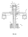
- FIGS. 8a, 8b and 9 show several components of apparatus 23, namely support cylinder 24, frame tube 25, and central shaft 26.
- the three components have concentric cylindrical structures with central shaft 26 and frame tube 25 as the innermost and outermost components, respectively.
- Support cylinder 24 has an expanding collet-like gripping structure at its upper end.
- the collet-like structure may be designed to grip and firmly hold multiple-pole stator inner casing 60.
- Annularly spaced finger-like clamp portions 24' which extend upwardly from tubular portions of support cylinder 24, form the collet-like structure.
- the number of clamps 24' may correspond to the number of poles 70 present in casing 60.
- Each clamp 24' may be intended to engage a corresponding one of poles 70.
- the collet-like gripping structure may be designed to operate through the common bores of inner casing 60 and fixture 13. Accordingly, the diameter of the collet-like structures (unbiased) may be less than the inner diameter of fixture 13.
- widths of clamps 24' and the inter-clamp spacings may be designed so that clamps 24' can freely move without interference through spacings 13'' between slats 13' of fixture 13 (FIG. 6).
- a frusto-conical shape plug 26' on top of central shaft 26 may be used to engage clamps 24' to bias them (24') against poles 70 through spacings 13''.
- Lengths of support cylinder 24 below the collet-like structures also may have a diameter, which is smaller than the inner diameter of fixture 13. In which case, the smaller-diameter lengths of support cylinder 24 also can pass through the bore of fixture 13.
- lengths of support cylinder 24 below the length necessary to insert the collet-like structures up to the top of casing 60 may have a diameter that is larger than the inner diameter of fixture 13.
- Support cylinder 24 shown herein, for example, in FIGS. 7, 8a, 8b and 10, corresponds to the latter alternative.
- Lengths of exemplary support cylinder 24 below ledge surface 24''' have a diameter, which is small enough for passage into support structure 12 bore, but which is sufficiently large to disallow passage through (inner) fixture 13 bore.
- Apparatus 23 may be suitably configured so that the three concentric cylindrical components (support cylinder 24, frame tube 25 and central shaft 26) can, individually or in various combinations, move vertically. Support cylinder 24 also may rotate. Conventional motor drive or actuator arrangements may be used to move the various components.
- FIG. 9 shows an exemplary arrangement. In the exemplary arrangement, frame tube 25 is slidably seated in a vertical external tube 31. (Support cylinder 24 and, central shaft 26 are seated in frame tube 25.) External tube 31 is mechanically connected by sheet 31' to vertical guides 31'', which, for example, are mounted on the frame of winder 20'. A linear actuator 35 drives guides 31'' (and attached external tube 31) up or down.
- a horizontal enclosure 25' is attached to the bottom end of frame tube 25.
- a linear actuator 32 is mounted on sheet 31' with its vertically movable shaft attached to enclosure 25'. By this attachment, frame tube 25 may move vertically relative to external cylinder 31 in response to actuator 32 actions.
- another linear actuator 33 is mounted on enclosure 25'. Actuator 33 is coupled to the bottom of central shaft 26 through coupler 34. By this coupling, actuator 33 may push or pull central shaft 26 up or down in support cylinder 24.
- bearings 30 are mounted in frame 25 to enable smooth rotation of support cylinder 24 around axis X.
- a motor 29 is mounted on enclosure 25' for controlled rotation of support cylinder 24. Motor 29 may impart rotary motion to support cylinder 24 through the combination of meshed gears 28 and 24'' that are respectively mounted on a shaft of motor 29 and the bottom of support cylinder 24. Gears 28 and 24'' are enclosed in enclosure 25'.
- a preliminary procedure involves firmly gripping casing 60 with the collet-like structure atop support cylinder 24.
- shaft 26 is pushed up through cylinder 24 by actuator 33 so that clamps 24' are in an unbiased state.
- clamps 24' may be radially aligned with spacings 13'' by turning support cylinder 24 using motor 29.
- linear actuator 32 raises frame tube 25 (with concentric structures 24 and 26) to insert unbiased clamps 24' into the common bore of inner casing 60 and fixture 13 for engagement with pole shoes 72.
- ledge surface 24''' of support cylinder 24 may come in contact with the bottom end of fixture 13 (FIG. 8b).
- actuator 33 retracts or pulls shaft 26 downward so that frusto-conical plug 26' engages and biases clamps 24'.
- Biased clamps 24' expand radially outward and deflect through spacings 13'' to contact pole shoe 72 surfaces. By design expanded or deflected clamps 24' radially press against pole shoes 72, and thereby firmly grip inner casing 60.
- actuator 35 drives guides 31'' upward. Consequently, frame tube 25 (which rests in external tube 31) and concentric inner structures 24 and 26 all move upward. Their upward movement lifts gripped casing 60 from pallet 10.
- ledge surface 24''' of support cylinder 24 pushes fixture 13 free of spring-loaded fastening ball 14, and thus detaches fixture 13 from support structure 12. Detached fixture 13 may rest on ledge surface 24''' (FIG. 10). Then further upward movement of guides 31'' driven by actuator 35 raises gripped inner casing 60 to a desired work position in vertical alignment with flyer 20.
- stator inner casing 60 may be raised to the work position without having to detach and carry along fixture 13.
- lengths of support cylinder 24'' below the collet-like structures have a small diameter which permits passage into fixture 13 bore (not shown).
- clamps 24' FIG. 8b
- support cylinder 24 is moved upward through suitably modified fixture 13 to raise inner casing 60 above fixture 13.
- fixture 13 may be modified to have a bore that is open at its top end. The modification may be obtained by using fixture 13 without optional cap 13''' or removing cap 13''' prior to lifting inner casing 60 from pallet 10. In either case, inner casing 60 may be raised to the work position with biased clamps 24' sliding up through fixture spacings 13''.
- Stator inner casing 60 which has been raised using either embodiment of apparatus 23, further may be rotationally indexed around axis X.
- Motor 29 may be used to turn support cylinder 24 to index raised inner casing 60.
- the indexing may, for example, sequentially present poles 70 one by one for wire coil winding by flyer 20.
- Winder 120' which has additional mechanical features for controlling the wire coil deposition in the pockets of raised stator inner casing 60, is described herein with reference to FIGS. 11, 12, 13 and 14.
- Winder 120' includes flyer arm 120 and a pair of wire guides, namely guides 100 and 101.
- Wire guides 100 and 101 are shaped to include sloped wire-running portions or surfaces (e.g. 100a and 101a, respectively) that smoothly extend into wire drop surfaces (100b and 101b, respectively).
- Wire drop surfaces 100b and 101b may be vertical or almost vertical.
- Guides 100 and 101, and flyer arm 120 can translate in directions X1 and X2, and also in directions Y1 and Y2.
- Winder 120' may also include optional pairs of supplementary wire guides namely guides 200 and 201, and 300 and 301.
- Other conventional parts or portions of winder 120' may, for example, be similar to those of winder 20'.
- these conventional portions e.g., frame, shafts, and drive mechanisms are omitted from the FIGS.
- Winder 120' may advantageously be used for depositing layered and tightly wound wire coils in pocket 62 adjoining subject pole piece 70 that has been indexed or presented for wire coil winding.
- FIG. 11 shows a disposition of two guides 100 and 101, and flyer arm 120 relative to pocket 62. Guides 100 and 101 are respectively aligned with top end 62top and bottom end 62bot of pocket 62.
- flyer arm 120 rotates around axis 102 in direction D1, and dispenses tensioned wire W into coil pocket 62.
- a length of tensioned wire W stretches from flyer arm 120 to that portion of a wire coil turn, which is already deposited or formed in coil pocket 62.
- Guide portions or surfaces 100a and 101a cooperatively alternate in intercepting wire W as flyer arm 120 rotates around axis 102.
- the intercepted wire W runs down portions or surfaces 100a (or 101a) and is dropped along terminal drop surfaces 100b (or 101b) into pocket 62.
- the dropped wire is deposited in pocket 62 along the foot of the drop surfaces.
- wire turns may be deposited at specific locations in pocket 62 by aligning drop surfaces 100b and 101b with those specific locations.
- This operational capability of winder 120' may be used to control the deposition of wire in pocket 62 and, for example, to wind wire coils in successive layers.
- the controlled deposition of wire coils in pocket 62 in successive layers may be advantageous in obtaining tightly wound coils and in achieving desirable high wire turn occupancy.
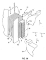
- FIGS. 12, 13, and 14 show details of the formation of a layered wire coil in pocket 62.
- FIG. 13 depicts the winding state at the start of the deposition of the layered wire coil.
- the deposition of the first wire coil layer starts with a first wire turn (wt1) deposited at the far or interior end of pocket 62.
- FIG. 12 depicts a later winding state in which the first layer (L1) and a partial second layer (L2) of the layered wire coil have been formed by wire turns wt.
- L1 and L2 partial second layer
- the wire turns shown in FIG. 12 may have been wound in pocket 62 by previous excursions of flyer 120 around axis 102.
- Drop position Hi is located in pocket 62 at the foot of surface 100b (i.e., at a location below but slightly to the left of the vertical drop of surface 100b).
- Drop position Hi is adjacent to the most recently deposited wire turn in partial layer L2.
- wire W dispensed by flyer 120 is shown as being pulled or dropped over surface 100b in to position Hi at the foot of portion 100b to form the next turn in second layer L2 of the wire coil.
- guides 100 and 101 are controllably moved laterally along directions X1 (or X2) to advance their foot positions (e.g., drop position Hi) to place the impending wire turn adjacent to the most recently deposited wire turn in a layer.
- the lateral guide and flyer movements which may be continuous or intermittent, are synchronized with the rotational position of flyer 120 around axis 102.
- surfaces 100b and 101b may be positioned sufficiently close to the top surface of the partially deposited wire layer (e.g., layer L2) to preclude the possibility of dropped wire slipping underneath surfaces 100b and 101b and over previously deposited turns (e.g., in area AW1).
- outer or front sidewalls PS of pocket 62 may have suitable cutouts PA to provide clear passages for the lateral movement of guides 100 and 101 while keeping guides surfaces 100b and 101b close to the top surfaces of the developing wire coil (FIG. 14).
- the first turn of an upper layer may be placed vertically above the last or final wire turn of the preceding completed layer (e.g., layer L1).
- the separation of guides 100 and 101 in directions Y1 and Y2 perpendicular to the plane of the completed layer may be increased.
- the increase may be calibrated to raise the bottom ends of guides 100b and 101b to the top of the new layer so that their respective drop positions (e.g., position Hi) are now on top of the final wire turn in a completed layer.
- the first turn of the new upper layer may be placed in the raised drop positions above the final turn of the completed layer.
- Subsequent wire turns in the new layer may deposited while moving the guide surfaces 100b and 101b laterally in directions X1 (or X2), as described previously.
- FIG. 13 shows the positions of the drop surfaces 100b and 101b at the initial stages of the formation of the first wire coil layer.
- flyer 120, and guides 100 and 101 may be moved in direction X1 toward the center of inner casing 60 to positions over the innermost areas (R1) adjacent to the back wall of pocket 62.
- Drop surfaces 100b and 101b may be placed close to the back wall so that their respective drop positions (e.g., position Hi) are adjacent to the back-wall.
- a first wire turn wt1 may be dropped or deposited adjacent to the back wall of pocket 62 by action of flyer 120 in the manner previously described.
- the first wire coil layer may be completely wound by placing successively adjacent wire turns in pocket 62 by moving flyer arm 120 and guides 100b and 101b laterally (in direction X2) as described previously.
- additional or supplemental wire guides may be used.
- the supplemental guides may be used to direct or guide tensioned wire W in advantageous orientations to pocket 62.
- the supplemental guides may, for example, be used to overcome geometrical obstructions in the path of wire W.
- FIG. 13 shows, for example, pockets adjacent to subject pole 70 that interfere with a straight-line path of wire W extending from flyer arm 120 to area R1 of pocket 62 adjoining subject pole 70.
- the interfering adjacent pocket structures are likely to snag or catch wire W dispensed by flyer 120.
- supplementary guides 200 and 201 may be positioned at the adjacent pole or pocket structures.
- supplementary guides 200 and 201 intercept wire W dispensed by flyer 120.
- Suitably shaped running surfaces on the guides 200 and 201 redirect the intercepted wire toward pocket 62.
- the intercepted wire may be redirected at suitable angles to the areas of pocket 62, where guide portions 100b and 101b are located to deposit wire turns.
- This use of supplementary guides 200 and 201 prevents wire snagging or catching by the interfering adjacent pole structures and allows tensioned wire W to be pulled around the innermost areas (R1) of pocket 62 at desirable pull angles by flyer 120.
- supplementary guides 300 and 301 may be used to guide or direct wire W to over come geometrical obstructions near the outermost areas (R2) of pocket 62.
- FIG. 13 shows, for example, supplementary guides 300 and 301 positioned at borders PB of the outer or front structures of pocket 62. Guides 300 and 301 prevent the front structures of pocket 62 from snagging or catching dispensed wire W. Also, suitably shaped running surfaces on the guides 300 and 301 allow redirection of wire W toward the outermost areas (R2) of pocket 62.
- stator inner casing 60 may be lowered to rest on support structure 12 on pallet 10.
- the lowering process may be conducted by suitable operation of apparatus 23.
- the lowering process is not described herein in any detail. However, it will be understood that the lowering process may, for example, generally proceed by suitably reversing some or all of the steps in the raising process described previously with reference to FIGS. 7, 8a, 8b, and 9.
- Lowered stator inner casing or subassembly 60 with wire coils wound in pockets 62 around poles 70 may be transported on pallet 10 to a workstation for fitting or locking inner casing 60 in a matching outer casing or support ring 44.
- Matching outer casing 44 may have complementary dovetail slots along its inner surface that match dovetail pins 76 extending radially from inner casing 60.
- a press unit 40 may be used for press-fitting inner and outer casings 60 and 44 together. Features of press unit 40 and its operation in conjunction with pallet 10 are described herein with reference to FIGS. 15, 16, and 17.
- press unit 40 includes a movable pressing block 41 underneath a movable backing or counter block 42.
- the two blocks are aligned facing each other along axis 40'.
- the two blocks may be used to press inner and outer casings 60 and 44 that are similarly aligned along axis 40' together.
- Press block 41 may have a suitable shape conforming to the shape of portions of the lower surface of pallet 10.
- press block 41 may have a cup-like surface 41b conforming to the tub-like bottom surface of support structure 12 that extends below plate 10a.
- the conformal contact surface 41b may be designed to ensure that during the operation of press 40, block 41 presses or pushes casing 60 along axis 40' with even or uniform pressure over the cross-section of casing 60.
- backing block 42 may have suitable shape for uniformly contacting outer casing or support ring 44.
- backing block 42 may have an annular seat or surface 42b conforming to the top surfaces of support ring 44.
- the conformal contact surface 42b may be designed to ensure that during the operation of press 40, block 42 presses against casing 44 along axis 40' with even or uniform pressure over the cross-section of casing 44.
- Press unit 40 also includes centering assembly 43.
- Assembly 43 may have an annular or ring-like structure, which may have a tapered bore.
- Assembly 43 may be made up of matching half portions, namely movable members 43' and 43''.
- Movable members 43' and 43" have open positions away from axis 40'.
- Members 43' and 43'' may close around axis 40', for example, in the manner of a clamshell, or by other suitable motion.
- members 43' and 43'' may support upright outer casing 44 in a cylindrical seat centered on axis 40'.
- Further backing block 42 may be lowered on outer casing 44 seated on closed members 43' and 43"to firmly hold outer casing 44 in a fixed upright position.
- Conventional drive means (not shown) may be used to move the various block or members in press unit 40.
- Members 43' and 43'' include dovetail guide ways, channels, or grooves along their inner cylindrical surfaces (in closed position), which lead to the dovetail slots in uprightly seated outer casing 44.
- the dovetail channels may be designed to suitably align and direct all dovetail pins 76 of casing 60 into corresponding or complementary dovetail slots of outer casing 44 seated on members 43' and 43''.
- upper channel portions 43a may have dovetail cross sectional dimensions that are the same or identical to the dimensions of the dovetail slots in outer casing 44.
- portions 43a may have a vertical orientation with channel sides aligned with the sides of corresponding dovetail slots in outer casing 44.
- Lower channel portions 43b may have dovetail cross sectional dimensions that are larger or wider at the bottom opening, but which taper or grade down to the dimensions of upper portions 43a over the length of lower portions 43b. Additionally, lower portions 43b may start at a greater radial distance from axis 40' than vertical upper portions 43a and then slant or curve into the latter.
- pallet 10 carrying the former is brought to rest over block 41.
- Pallet 10 may be aligned so that the common central axis of support structure 12 and inner casing 60 coincides with axis 40' (FIG. 15).
- Matching outer casing 44 may be pre-positioned between block 42 and closed members 43' and 43'', with its (44) dovetail slots aligned with corresponding channels 43a (not shown).
- press block 41 may be raised to contact the underneath of plate 10a. Further upward movement of press block 41 lifts pallet 10 up from belts 11.
- the tub-like bottom portions of support structure 12 of lifted plate 10a may be seated or rest in matching cup-like surfaces 41b of block 41.
- the conformity between the tub-like bottom portions and cup-like surfaces 41b may allow block 41 to support lifted plate 10a over a large area and keep the latter in a stable horizontal orientation with inner casing 60 aligned along axis 40'.
- channels 43b receive dovetail pins 76 of inner casing 60. Received dovetail pins 76 are pushed up through channels 43b and 43a. In the process channels 43b and 43a align received dovetail pins 76 and direct them into the corresponding dovetail slots of outer casing 44. Aligned dovetail pins 76 slide into the corresponding outer casing dovetail slots as inner casing 60 is pushed up and pressed into outer casing 44 (FIG. 12) by upward movement of block 41.
- the slant or curved orientation of channels 43b leading to vertical channels 43a may allow for some radial compression of pole pins 76 and inner casing 60 as the latter are pushed up. This radial compression may advantageously allow tight-fitting inner casing 60 to slide into outer casing 44 smoothly.
- outer casing 44 may be pushed down over inner casing 60.
- Press 40 may be suitably modified, for example, by enabling additional downward movement of members 43' and 43''.
- block 41 may be raised to firmly support pallet 10 carrying inner casing 60.
- Matching outer casing 44 may be seated upright, sandwiched between block 42 and closed members 43' and 43''. Then the entire upper assembly (42, 44, 43' and 43'') may be lowered to push or press outer casing 44 over inner casing 60.
- channels 43a and 43b may function in a manner similar to that described above to gather and direct dovetail pins 76 into corresponding dovetail slots in outer casing 44.
Landscapes
- Engineering & Computer Science (AREA)
- Manufacturing & Machinery (AREA)
- Power Engineering (AREA)
- Manufacture Of Motors, Generators (AREA)
Applications Claiming Priority (6)
| Application Number | Priority Date | Filing Date | Title |
|---|---|---|---|
| US35211602P | 2002-01-25 | 2002-01-25 | |
| US352116P | 2002-01-25 | ||
| US37467502P | 2002-04-22 | 2002-04-22 | |
| US374675P | 2002-04-22 | ||
| US10/350,671 US20060103257A1 (en) | 2002-01-25 | 2003-01-22 | Segmented dynamo-machine component fabrication |
| US350671 | 2003-01-22 |
Publications (2)
| Publication Number | Publication Date |
|---|---|
| EP1331719A2 true EP1331719A2 (de) | 2003-07-30 |
| EP1331719A3 EP1331719A3 (de) | 2006-05-10 |
Family
ID=27407959
Family Applications (1)
| Application Number | Title | Priority Date | Filing Date |
|---|---|---|---|
| EP03001589A Withdrawn EP1331719A3 (de) | 2002-01-25 | 2003-01-24 | Herstellung einer segmentierten elektrischen Maschine |
Country Status (3)
| Country | Link |
|---|---|
| US (1) | US20060103257A1 (de) |
| EP (1) | EP1331719A3 (de) |
| CA (1) | CA2417079A1 (de) |
Cited By (4)
| Publication number | Priority date | Publication date | Assignee | Title |
|---|---|---|---|---|
| WO2005027307A1 (de) * | 2003-09-10 | 2005-03-24 | Kress-Elektrik Gmbh & Co. Elektromotorenfabrik | Stator für einen elektromotor |
| ITPI20130020A1 (it) * | 2013-03-20 | 2014-09-21 | Atop Spa | Apparecchiatura e metodo per produrre statori di macchine dinamoelettriche formati da un assemblato di segmenti di polo |
| ITMI20132206A1 (it) * | 2013-12-24 | 2015-06-25 | Marsilli & Co | Dispositivo per eseguire l'inserimento, l'avvolgimento e la stratificazione di un filo su uno o piu' nuclei statorici o rotorici. |
| CN112186982A (zh) * | 2019-07-04 | 2021-01-05 | 本田技研工业株式会社 | 旋转电机组装装置以及旋转电机组装方法 |
Families Citing this family (3)
| Publication number | Priority date | Publication date | Assignee | Title |
|---|---|---|---|---|
| DE102017220424B4 (de) * | 2017-11-16 | 2021-01-14 | Vitesco Technologies GmbH | Werkzeug und Verfahren zur Anordnung eines Stators in ein Gehäuse |
| CN109660082B (zh) * | 2019-01-31 | 2023-10-20 | 重庆昆旺电子有限责任公司 | 电机装配工艺 |
| CN117760365B (zh) * | 2024-01-04 | 2024-07-30 | 杭州三共机械有限公司 | 一种平型轴式分度器检测装置及方法 |
Family Cites Families (8)
| Publication number | Priority date | Publication date | Assignee | Title |
|---|---|---|---|---|
| GB2172444B (en) * | 1985-03-09 | 1988-08-17 | Asmo Co Ltd | Stator for an electric motor |
| JPS62126843A (ja) * | 1985-11-25 | 1987-06-09 | Matsushita Electric Ind Co Ltd | 扁平モ−タの電機子の製造方法 |
| JPH0318251A (ja) * | 1989-06-14 | 1991-01-25 | Matsushita Electric Ind Co Ltd | 回転機用固定子の製造方法 |
| JP2811815B2 (ja) * | 1989-10-13 | 1998-10-15 | 松下電器産業株式会社 | 回転機用固定子の製造方法 |
| JP3558689B2 (ja) * | 1994-07-20 | 2004-08-25 | 松下電器産業株式会社 | 分割円筒体の組立治具及び組立方法 |
| US5653014A (en) * | 1994-09-13 | 1997-08-05 | Axis Usa, Inc. | Dynamo-electric machine component conveying systems and load/unload devices |
| JPH08140315A (ja) * | 1994-11-07 | 1996-05-31 | Toshiba Corp | 筒状積層鉄心の製造装置 |
| CA2295430A1 (en) * | 1999-01-13 | 2000-07-13 | Sabatino Luciani | Dynamo-electric machine stators with multiple poles, and methods and apparatus for winding same |
-
2003
- 2003-01-22 US US10/350,671 patent/US20060103257A1/en not_active Abandoned
- 2003-01-24 CA CA002417079A patent/CA2417079A1/en not_active Abandoned
- 2003-01-24 EP EP03001589A patent/EP1331719A3/de not_active Withdrawn
Cited By (11)
| Publication number | Priority date | Publication date | Assignee | Title |
|---|---|---|---|---|
| WO2005027307A1 (de) * | 2003-09-10 | 2005-03-24 | Kress-Elektrik Gmbh & Co. Elektromotorenfabrik | Stator für einen elektromotor |
| ITPI20130020A1 (it) * | 2013-03-20 | 2014-09-21 | Atop Spa | Apparecchiatura e metodo per produrre statori di macchine dinamoelettriche formati da un assemblato di segmenti di polo |
| WO2014147535A1 (en) * | 2013-03-20 | 2014-09-25 | Atop S.P.A. | Apparatus and method for producing stators of dynamo electric machines formed from an assembly of pole segments |
| CN105190801A (zh) * | 2013-03-20 | 2015-12-23 | Atop有限公司 | 用于制造由磁极段组件形成的电机定子的设备和方法 |
| CN105190801B (zh) * | 2013-03-20 | 2017-12-12 | Atop有限公司 | 用于制造由磁极段组件形成的电机定子的设备和方法 |
| US10050498B2 (en) | 2013-03-20 | 2018-08-14 | Atop S.P.A. | Apparatus for producing wound stators of dynamo electric machines formed from assembly of pole segments |
| US10804775B2 (en) | 2013-03-20 | 2020-10-13 | Atop S.P.A. | Method for producing stators of dynamo electric machines formed from an assembly of pole segments |
| ITMI20132206A1 (it) * | 2013-12-24 | 2015-06-25 | Marsilli & Co | Dispositivo per eseguire l'inserimento, l'avvolgimento e la stratificazione di un filo su uno o piu' nuclei statorici o rotorici. |
| EP2889990A1 (de) * | 2013-12-24 | 2015-07-01 | Marsilli & Co. S.P.A. | Vorrichtung zum Einsetzen, Aufwickeln und Beschichten eines Drahts auf einem oder mehreren Stator- oder Rotorkernen |
| CN112186982A (zh) * | 2019-07-04 | 2021-01-05 | 本田技研工业株式会社 | 旋转电机组装装置以及旋转电机组装方法 |
| CN112186982B (zh) * | 2019-07-04 | 2023-10-17 | 本田技研工业株式会社 | 旋转电机组装装置以及旋转电机组装方法 |
Also Published As
| Publication number | Publication date |
|---|---|
| US20060103257A1 (en) | 2006-05-18 |
| EP1331719A3 (de) | 2006-05-10 |
| CA2417079A1 (en) | 2003-07-25 |
Similar Documents
| Publication | Publication Date | Title |
|---|---|---|
| WO2019093515A1 (ja) | コイルセグメント加工方法、コイルセグメント加工装置及びコイルセグメントの接続構造 | |
| KR102731533B1 (ko) | 헤어핀 도체의 레그의 적어도 제 1 쌍의 단부를 위치시키기 위한 장치 및 방법 | |
| CA2670849C (en) | Stator manufacturing apparatus | |
| US3791419A (en) | Apparatus and method for forming wave winding for dynamoelectric machine | |
| US7886426B2 (en) | Stator manufacturing apparatus | |
| KR20040018299A (ko) | 모터의 제조방법 | |
| KR20170095266A (ko) | 스테이터의 제조 장치 및 그 제조 방법 | |
| CN113454893A (zh) | 线圈插入装置以及线圈插入方法 | |
| CN100477453C (zh) | 绕线装置和方法 | |
| JP3762929B1 (ja) | パラ巻線方法及びパラ巻線装置 | |
| JP5204627B2 (ja) | 連結コイル巻線方法および連結コイル巻線装置 | |
| EP1331719A2 (de) | Herstellung einer segmentierten elektrischen Maschine | |
| KR101346715B1 (ko) | 다이나모 전기 기계 코어 내의 복수개의 와이어의 리드를 종결시키기 위한 방법 및 장치 | |
| EP1609231B1 (de) | Verfahren und gerät zur einführung von spulenanschlussen | |
| US7467648B2 (en) | Coil forming and inserting device and coil forming and inserting method | |
| JPH06303748A (ja) | 波形状巻線製造方法および波形状巻線製造装置 | |
| US4299023A (en) | Machine for winding and inserting coils | |
| KR900002417B1 (ko) | 교류 발전기 고정자코아의 코일권선 및 삽입방법과 그 장치 | |
| EP1750355A2 (de) | Spulenwickel- und Entladevorrichtung | |
| CN118232638B (zh) | 一种电机转子自动装配一体机 | |
| KR102854853B1 (ko) | 헤어핀 타입 고정자 코일의 얼라인 장치 | |
| GB1599353A (en) | Stator assemblies for dynamoelectric machines | |
| JP2024516034A (ja) | 電気モータ用固定子の製造方法および各電気モータ用固定子 | |
| CN101536291B (zh) | 用于终止电动发电机芯部中多根金属线的引线的方法和设备 | |
| JP2541381B2 (ja) | コイル挿入装置 |
Legal Events
| Date | Code | Title | Description |
|---|---|---|---|
| PUAI | Public reference made under article 153(3) epc to a published international application that has entered the european phase |
Free format text: ORIGINAL CODE: 0009012 |
|
| AK | Designated contracting states |
Designated state(s): AT BE BG CH CY CZ DE DK EE ES FI FR GB GR HU IE IT LI LU MC NL PT SE SI SK TR |
|
| AX | Request for extension of the european patent |
Extension state: AL LT LV MK RO |
|
| PUAL | Search report despatched |
Free format text: ORIGINAL CODE: 0009013 |
|
| AK | Designated contracting states |
Kind code of ref document: A3 Designated state(s): AT BE BG CH CY CZ DE DK EE ES FI FR GB GR HU IE IT LI LU MC NL PT SE SI SK TR |
|
| AX | Request for extension of the european patent |
Extension state: AL LT LV MK RO |
|
| AKX | Designation fees paid | ||
| REG | Reference to a national code |
Ref country code: DE Ref legal event code: 8566 |
|
| STAA | Information on the status of an ep patent application or granted ep patent |
Free format text: STATUS: THE APPLICATION IS DEEMED TO BE WITHDRAWN |
|
| 18D | Application deemed to be withdrawn |
Effective date: 20061111 |