EP1332834A1 - Trennschleifscheibe mit seitlichen Stahlblechen - Google Patents
Trennschleifscheibe mit seitlichen Stahlblechen Download PDFInfo
- Publication number
- EP1332834A1 EP1332834A1 EP02001641A EP02001641A EP1332834A1 EP 1332834 A1 EP1332834 A1 EP 1332834A1 EP 02001641 A EP02001641 A EP 02001641A EP 02001641 A EP02001641 A EP 02001641A EP 1332834 A1 EP1332834 A1 EP 1332834A1
- Authority
- EP
- European Patent Office
- Prior art keywords
- cutting disc
- steel
- steel sheets
- cutting
- grids
- Prior art date
- Legal status (The legal status is an assumption and is not a legal conclusion. Google has not performed a legal analysis and makes no representation as to the accuracy of the status listed.)
- Granted
Links
Images


Classifications
-
- B—PERFORMING OPERATIONS; TRANSPORTING
- B24—GRINDING; POLISHING
- B24D—TOOLS FOR GRINDING, BUFFING OR SHARPENING
- B24D5/00—Bonded abrasive wheels, or wheels with inserted abrasive blocks, designed for acting only by their periphery; Bushings or mountings therefor
- B24D5/12—Cut-off wheels
-
- B—PERFORMING OPERATIONS; TRANSPORTING
- B24—GRINDING; POLISHING
- B24D—TOOLS FOR GRINDING, BUFFING OR SHARPENING
- B24D5/00—Bonded abrasive wheels, or wheels with inserted abrasive blocks, designed for acting only by their periphery; Bushings or mountings therefor
- B24D5/16—Bushings; Mountings
Definitions
- the present invention relates to a cutting disc, in particular with a Diameter for over 500 mm, and a method for producing such Cutting disc.
- Object of the present invention is therefore to provide a cutting disc, the despite being stable in relation to the diameter of a small disk thickness, wherein At the same time the problems of the known approaches are avoided.
- the steel sheets applied laterally to the axial end faces of the cutting disk or steel grids lead to a large-scale distribution of the clamping flanges outgoing clamping forces.
- the cutting disc is stabilized over a large area.
- the Cutting depth not reduced. This is especially true when the steel sheets or Steel grille inserted flush in recesses in the side surfaces of the cutting disc are as a preferred embodiment provides.
- the steel sheets or steel mesh are glued to the cutting disc.
- the steel sheets or steel mesh can thus also in the edge zones of the cutting disc Optionally absorb occurring bending stresses, so that a tumbling effect is prevented.
- the Steel sheets or steel mesh have a substantially round shape.
- the inventive method provides that the steel sheets or steel mesh together with the binder, the abrasive grain and any fillers of the Cutting disc pressed and then cured.
- This Production process is particularly favorable in terms of production technology and secures at the same time a firm hold of the steel sheets or steel mesh.
- This hold can be further improved by using the steel sheets or Steel grid before pressing on the side facing the blade with a Glue, in particular epoxy glue, be provided.
- the cutting disc 1 shown in the figures is a Resin-bonded grinding wheel.
- a resin various phenolic resins used by their targeted selection in conjunction with the choice of Abrasive and the fillers the grinding behavior and the degree of hardness of Cutting disc is adapted to the respective requirements.
- abrasives are preferred conventional abrasives such as silicon carbide and Corundum used.
- fillers are mainly solid lubricants, for example Pyrite and graphite, as well as common powdered materials for plastic reinforcement such Calcium carbonate or glass powder.
- the diameter d of the cutting wheel 1 is typically between 800 mm and 1800 mm.
- the ratio of diameter d to width b is over 80, preferably even over 100. This ratio is due to the present Invention be further increased. It should be noted that the width b of the Cutting disc 1 for reasons of clarity in the figures in relation to Diameter d is drawn many times too large.
- the cutting disk 1 has recesses 3 in the lateral end faces, which are extend over a diameter range of diameter d from 45% to 80%. In the recesses 3, the steel sheets or steel mesh 2 are substantially flush used.
- the steel sheets or steel mesh 2 have a minimum thickness of 0.5 mm and can be up to 3.0 mm thick, with common values being more likely between 1.0 mm and 2.0 mm lie.
- the steel sheets form a closed surface, whereas under Steel mesh structures are understood, the recesses, in particular have rectangular recesses.
- the steel sheets or steel mesh 2 are with glued the remaining blade 1.
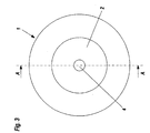
- the steel sheets 2 are round in the embodiment shown, as shown in FIG. 3rd seen. Even if the round shape is favorable for quiet concentricity, are also any other shapes, especially polygons, conceivable.
- Fig. 1 the two cooperating clamping flanges 5a and 5b are shown, with where the power is transmitted to the cutting wheel 1.
- the steel sheets or Steel grille 2 cause the introduction of force not only to the area of Clamping flanges 5a and 5b remains limited, but essentially to the extends the entire surface covering the steel sheets or steel mesh 2.
- the Stabilization of the cutting wheel 1 thus extends radially far outward.
- the cutting disc 1 aullege a fabric insert 6. It is a resin-impregnated glass fiber fabric.
- the fabric insert 6 stabilizes the blade 1 and prevents the formation of stray Slice fragments in case of failure of the disc.
- the present invention allows to get along with only one or at least a few fabric inserts 6. Also conceivable is a variant without tissue insert. This is insofar advantageous, as in reduction of the tissue layers, the volume of the tissue through Schleifkom can be replaced, whereby the grinding properties are improved.
- the preparation of the cutting discs according to the invention is such that from Abrasive grain, synthetic resin and fillers a mixture is made. On a round Press plate is first placed a steel or steel mesh 2 and then the Mixture of abrasive grain, synthetic resin and fillers applied. In this mixture the fabric inserts 6 are inserted. Then it is compressed, taking at the Surface is formed a recess 3. In this recess 3, the second Steel plate or steel grille 2 inserted, after which a further pressing takes place. The steel sheets or steel mesh 2 are applied to the before processing Cutting disc 1 facing side provided with an epoxy adhesive.
- the pressed sandwich is then clamped between straightening plates and in Oven cured at a suitable temperature.
Landscapes
- Engineering & Computer Science (AREA)
- Mechanical Engineering (AREA)
- Polishing Bodies And Polishing Tools (AREA)
- Sawing (AREA)
- Milling Processes (AREA)
- Straightening Metal Sheet-Like Bodies (AREA)
- Shearing Machines (AREA)
- Handcart (AREA)
Abstract
Description
Claims (11)
- Trennscheibe (1), insbesondere mit einem Durchmesser über 500 mm, dadurch gekennzeichnet, daß die Trennscheibe (1) seitlich mit Stahlblechen oder Stahlgittern (2) mit einer Mindeststärke von 0,5 mm versehen ist.
- Trennscheibe nach Anspruch 1, dadurch gekennzeichnet, daß die Stärke der Stahlbleche oder Stahlgitter (2) zwischen 0,5 mm und 3,0 mm, vorzugsweise zwischen 1,0 mm und 2,0 mm liegt.
- Trennscheibe nach Anspruch 1 oder 2, dadurch gekennzeichnet, daß die Stahlbleche oder Stahlgitter (2) bündig in Vertiefungen (3) in den Seitenflächen der Trennscheibe (1) eingefügt sind.
- Trennscheibe nach einem Ansprüche 1 bis 3, dadurch gekennzeichnet, daß die Stahlbleche oder Stahlgitter (2) mit der Trennscheibe (1) verklebt sind.
- Trennscheibe nach einem Ansprüche 1 bis 4, dadurch gekennzeichnet, daß die Stahlbleche oder Stahlgitter (2) im wesentlichen eine runde Form aufweisen.
- Trennscheibe nach einem Ansprüche 1 bis 5, dadurch gekennzeichnet, daß die radiale Erstreckung der Stahlbleche oder Stahlgitter (2) von der Mittelbohrung (4) bis maximal 80 % des Durchmessers (d) der Trennscheibe (1) reicht.
- Trennscheibe nach einem Ansprüche 1 bis 6, dadurch gekennzeichnet, daß die Verhältniszahl von Durchmesser (d) der Trennscheibe (1) zu Breite (b) der Trennscheibe (1) über 80 liegt.
- Trennscheibe nach einem Ansprüche 1 bis 7, dadurch gekennzeichnet, daß die Trennscheibe (1) Kunstharz als Bindemittel aufweist.
- Trennscheibe nach einem Ansprüche 1 bis 8, dadurch gekennzeichnet, daß die Trennscheibe (1) mindestens eine Gewebeeinlage (6) aufweist.
- Verfahren zur Herstellung einer Trennscheibe nach einem der Ansprüche 1 bis 9, dadurch gekennzeichnet, daß die Stahlbleche oder Stahlgitter (2) gemeinsam mit dem Bindemittel, dem Schleifkorn und allfälligen Füllstoffen der Trennscheibe (1) verpreßt und anschließend ausgehärtet werden.
- Verfahren nach Anspruch 10, dadurch gekennzeichnet, daß die Stahlbleche oder Stahlgitter (2) vor dem Verpressen auf der der Trennscheibe (1) zugewandten Seite mit einem Kleber, insbesondere Epoxikleber, versehen werden.
Priority Applications (13)
| Application Number | Priority Date | Filing Date | Title |
|---|---|---|---|
| DE50200094T DE50200094D1 (de) | 2002-01-24 | 2002-01-24 | Trennschleifscheibe mit seitlichen Stahlblechen |
| SI200230006T SI1332834T1 (en) | 2002-01-24 | 2002-01-24 | Cut-off wheel with lateral steel plates |
| AT02001641T ATE253433T1 (de) | 2002-01-24 | 2002-01-24 | Trennschleifscheibe mit seitlichen stahlblechen |
| EP02001641A EP1332834B1 (de) | 2002-01-24 | 2002-01-24 | Trennschleifscheibe mit seitlichen Stahlblechen |
| DE20220516U DE20220516U1 (de) | 2002-01-24 | 2002-01-24 | Trennscheibe |
| DE20220787U DE20220787U1 (de) | 2002-01-24 | 2002-01-24 | Trennscheibe |
| ES02001641T ES2208616T3 (es) | 2002-01-24 | 2002-01-24 | Disco de corte por abrasion con chapas de acero laterales. |
| CNB038000865A CN100391695C (zh) | 2002-01-24 | 2003-01-23 | 有侧面钢板的切割砂轮 |
| PCT/AT2003/000022 WO2003061910A1 (de) | 2002-01-24 | 2003-01-23 | Trennschleifscheibe mit seitlichen stahlblechen |
| US10/472,572 US7115029B2 (en) | 2002-01-24 | 2003-01-23 | Abrasive cutting disk with lateral steel sheets |
| CZ20032522A CZ297689B6 (cs) | 2002-01-24 | 2003-01-23 | Rozbrusovací kotouc s bocními ocelovými plechy |
| PL362770A PL205513B1 (pl) | 2002-01-24 | 2003-01-23 | Ściernica tarczowa do cięcia i sposób wytwarzania ściernicy tarczowej do cięcia |
| BRPI0302833-0A BR0302833B1 (pt) | 2002-01-24 | 2003-01-23 | disco de corte com chapas de aço laterais |
Applications Claiming Priority (1)
| Application Number | Priority Date | Filing Date | Title |
|---|---|---|---|
| EP02001641A EP1332834B1 (de) | 2002-01-24 | 2002-01-24 | Trennschleifscheibe mit seitlichen Stahlblechen |
Publications (2)
| Publication Number | Publication Date |
|---|---|
| EP1332834A1 true EP1332834A1 (de) | 2003-08-06 |
| EP1332834B1 EP1332834B1 (de) | 2003-11-05 |
Family
ID=8185337
Family Applications (1)
| Application Number | Title | Priority Date | Filing Date |
|---|---|---|---|
| EP02001641A Expired - Lifetime EP1332834B1 (de) | 2002-01-24 | 2002-01-24 | Trennschleifscheibe mit seitlichen Stahlblechen |
Country Status (11)
| Country | Link |
|---|---|
| US (1) | US7115029B2 (de) |
| EP (1) | EP1332834B1 (de) |
| CN (1) | CN100391695C (de) |
| AT (1) | ATE253433T1 (de) |
| BR (1) | BR0302833B1 (de) |
| CZ (1) | CZ297689B6 (de) |
| DE (2) | DE20220787U1 (de) |
| ES (1) | ES2208616T3 (de) |
| PL (1) | PL205513B1 (de) |
| SI (1) | SI1332834T1 (de) |
| WO (1) | WO2003061910A1 (de) |
Cited By (6)
| Publication number | Priority date | Publication date | Assignee | Title |
|---|---|---|---|---|
| EP1611998A1 (de) * | 2004-07-03 | 2006-01-04 | August Rüggeberg GmbH & Co. KG | Trenn-Schleifscheibe für stationären Einsatz |
| WO2006042352A1 (de) | 2004-10-19 | 2006-04-27 | Gerhard Gissing | Trennschleifring mit doppelter kernspannvorrichtung |
| EP2353784A2 (de) | 2010-02-10 | 2011-08-10 | Rappold Winterthur Technologie GmbH | Verbundschleifsystem |
| EP2353783A2 (de) | 2010-01-20 | 2011-08-10 | Rappold Winterthur Technologie GmbH | Verbundschleifsystem |
| EP3278927A1 (de) * | 2016-08-04 | 2018-02-07 | Tyrolit - Schleifmittelwerke Swarovski K.G. | Trennscheibe |
| DE102019127702A1 (de) * | 2019-10-15 | 2021-04-15 | Battenfeld-Cincinnati Germany Gmbh | Trennmesser |
Families Citing this family (9)
| Publication number | Priority date | Publication date | Assignee | Title |
|---|---|---|---|---|
| EP2177318B1 (de) * | 2009-04-30 | 2014-03-26 | Saint-Gobain Abrasives, Inc. | Schleifartikel mit verbesserter Schleifkornbewahrung und -leistung |
| JP2011079113A (ja) * | 2009-10-09 | 2011-04-21 | Tenryu Saw Mfg Co Ltd | 円板状回転工具の取付け装置 |
| AT511244B1 (de) | 2011-03-30 | 2013-01-15 | Swarovski Tyrolit Schleif | Trennschleifscheibe |
| WO2014036097A1 (en) * | 2012-08-28 | 2014-03-06 | Saint-Gobain Abrasives, Inc. | Large diameter cutting tool |
| US20150105006A1 (en) * | 2013-10-11 | 2015-04-16 | HGST Netherlands B.V. | Method to sustain minimum required aspect ratios of diamond grinding blades throughout service lifetime |
| JP5893669B2 (ja) * | 2014-04-30 | 2016-03-23 | 富士製砥株式会社 | 回転砥石の製造法及び該製造法によって製造した回転砥石 |
| CN105313006A (zh) * | 2014-08-02 | 2016-02-10 | 宁波市弘美机械有限公司 | 一种行星轮抛光机 |
| EP3421178A1 (de) * | 2017-06-26 | 2019-01-02 | Dronco GmbH | Verfahren zur herstellung eines schleifelements, insbesondere einer rotierenden schleifscheibe, sowie schleifelement, insbesondere rotierende schleifscheibe |
| KR102558904B1 (ko) * | 2019-01-14 | 2023-07-21 | 아우구스트 뤼게베르크 게엠베하 운트 코. 카게 | 연삭 디스크 및 이러한 연삭 디스크의 용도 |
Citations (4)
| Publication number | Priority date | Publication date | Assignee | Title |
|---|---|---|---|---|
| US2033263A (en) * | 1927-12-07 | 1936-03-10 | Carborundum Co | Abrasive article |
| JPS5789564A (en) * | 1980-11-17 | 1982-06-03 | Niro Inoue | Diamond blade for cutting stone |
| US4718398A (en) * | 1985-09-04 | 1988-01-12 | Diamant Boart Societe Anonyme | Circular saw for stony materials |
| JPH06312314A (ja) * | 1993-04-26 | 1994-11-08 | Jiyanpu Kogyo Kk | カッター用基板 |
Family Cites Families (12)
| Publication number | Priority date | Publication date | Assignee | Title |
|---|---|---|---|---|
| US1600064A (en) * | 1925-12-08 | 1926-09-14 | George W Perks Company | Mounting for abrasive wheels |
| US1756259A (en) * | 1926-11-22 | 1930-04-29 | George W Perks Company | Mounting for abrasive wheels or the like |
| US2004630A (en) * | 1932-12-06 | 1935-06-11 | Krug Carl | Grinding disk |
| US2259554A (en) * | 1940-12-30 | 1941-10-21 | Safety Grinding Wheel & Machin | Abrasive wheel |
| US3526063A (en) * | 1965-03-08 | 1970-09-01 | Norton Co | Integral mounting means and reinforcement for grinding wheels |
| US3528203A (en) * | 1968-05-02 | 1970-09-15 | Bendix Corp | Grinding wheel |
| US3838543A (en) * | 1970-05-25 | 1974-10-01 | Norton Co | High speed cut-off wheel |
| US3898773A (en) * | 1973-08-28 | 1975-08-12 | Swarovski Tyrolit Schleif | Grinding disk |
| US3867795A (en) * | 1973-10-16 | 1975-02-25 | Norton Co | Composite resinoid bonded abrasive wheels |
| CN2314892Y (zh) * | 1997-11-03 | 1999-04-21 | 李广棋 | 超薄切割砂轮片 |
| IT1306051B1 (it) * | 1998-05-26 | 2001-05-29 | Vittorio Pareti | Foglio antivibrazioni per dischi da taglio |
| TW550141B (en) * | 1999-07-29 | 2003-09-01 | Saint Gobain Abrasives Inc | Depressed center abrasive wheel assembly and abrasive wheel assembly |
-
2002
- 2002-01-24 DE DE20220787U patent/DE20220787U1/de not_active Expired - Lifetime
- 2002-01-24 SI SI200230006T patent/SI1332834T1/xx unknown
- 2002-01-24 ES ES02001641T patent/ES2208616T3/es not_active Expired - Lifetime
- 2002-01-24 AT AT02001641T patent/ATE253433T1/de active
- 2002-01-24 DE DE50200094T patent/DE50200094D1/de not_active Expired - Lifetime
- 2002-01-24 EP EP02001641A patent/EP1332834B1/de not_active Expired - Lifetime
-
2003
- 2003-01-23 US US10/472,572 patent/US7115029B2/en not_active Expired - Fee Related
- 2003-01-23 WO PCT/AT2003/000022 patent/WO2003061910A1/de not_active Ceased
- 2003-01-23 CN CNB038000865A patent/CN100391695C/zh not_active Expired - Fee Related
- 2003-01-23 BR BRPI0302833-0A patent/BR0302833B1/pt not_active IP Right Cessation
- 2003-01-23 CZ CZ20032522A patent/CZ297689B6/cs not_active IP Right Cessation
- 2003-01-23 PL PL362770A patent/PL205513B1/pl unknown
Patent Citations (4)
| Publication number | Priority date | Publication date | Assignee | Title |
|---|---|---|---|---|
| US2033263A (en) * | 1927-12-07 | 1936-03-10 | Carborundum Co | Abrasive article |
| JPS5789564A (en) * | 1980-11-17 | 1982-06-03 | Niro Inoue | Diamond blade for cutting stone |
| US4718398A (en) * | 1985-09-04 | 1988-01-12 | Diamant Boart Societe Anonyme | Circular saw for stony materials |
| JPH06312314A (ja) * | 1993-04-26 | 1994-11-08 | Jiyanpu Kogyo Kk | カッター用基板 |
Non-Patent Citations (2)
| Title |
|---|
| PATENT ABSTRACTS OF JAPAN vol. 006, no. 181 (M - 156) 17 September 1982 (1982-09-17) * |
| PATENT ABSTRACTS OF JAPAN vol. 1995, no. 02 31 March 1995 (1995-03-31) * |
Cited By (11)
| Publication number | Priority date | Publication date | Assignee | Title |
|---|---|---|---|---|
| EP1611998A1 (de) * | 2004-07-03 | 2006-01-04 | August Rüggeberg GmbH & Co. KG | Trenn-Schleifscheibe für stationären Einsatz |
| WO2006042352A1 (de) | 2004-10-19 | 2006-04-27 | Gerhard Gissing | Trennschleifring mit doppelter kernspannvorrichtung |
| AT502285B1 (de) * | 2004-10-19 | 2008-12-15 | Gissing Gerhard | Trennschleifring mit doppelter kernspannvorrichtung |
| RU2366563C2 (ru) * | 2004-10-19 | 2009-09-10 | Герхард Гиссинг | Отрезное абразивное устройство и способ его изготовления |
| US8113920B2 (en) | 2004-10-19 | 2012-02-14 | Gerhard Gissing | Cut-off wheel comprising a double core clamping device |
| EP2353783A2 (de) | 2010-01-20 | 2011-08-10 | Rappold Winterthur Technologie GmbH | Verbundschleifsystem |
| EP2353784A2 (de) | 2010-02-10 | 2011-08-10 | Rappold Winterthur Technologie GmbH | Verbundschleifsystem |
| EP3278927A1 (de) * | 2016-08-04 | 2018-02-07 | Tyrolit - Schleifmittelwerke Swarovski K.G. | Trennscheibe |
| AT518913A1 (de) * | 2016-08-04 | 2018-02-15 | Tyrolit Schleifmittelwerke Swarovski Kg | Trennscheibe |
| AT518913B1 (de) * | 2016-08-04 | 2019-04-15 | Tyrolit Schleifmittelwerke Swarovski Kg | Trennscheibe |
| DE102019127702A1 (de) * | 2019-10-15 | 2021-04-15 | Battenfeld-Cincinnati Germany Gmbh | Trennmesser |
Also Published As
| Publication number | Publication date |
|---|---|
| PL205513B1 (pl) | 2010-04-30 |
| CN1498151A (zh) | 2004-05-19 |
| EP1332834B1 (de) | 2003-11-05 |
| US20050107020A1 (en) | 2005-05-19 |
| US7115029B2 (en) | 2006-10-03 |
| CZ297689B6 (cs) | 2007-03-07 |
| DE20220787U1 (de) | 2004-03-11 |
| CZ20032522A3 (cs) | 2003-12-17 |
| DE50200094D1 (de) | 2003-12-11 |
| WO2003061910A1 (de) | 2003-07-31 |
| ES2208616T3 (es) | 2004-06-16 |
| CN100391695C (zh) | 2008-06-04 |
| BR0302833A (pt) | 2004-03-02 |
| ATE253433T1 (de) | 2003-11-15 |
| BR0302833B1 (pt) | 2012-03-20 |
| SI1332834T1 (en) | 2004-02-29 |
| PL362770A1 (en) | 2004-11-02 |
Similar Documents
| Publication | Publication Date | Title |
|---|---|---|
| EP1332834B1 (de) | Trennschleifscheibe mit seitlichen Stahlblechen | |
| EP0229983B1 (de) | Schleifscheibe mit Dämpfung | |
| DE69110075T2 (de) | Schleifmittel. | |
| DE2536090A1 (de) | Schleifkoerper und verfahren zu seiner herstellung | |
| DE1652916C3 (de) | Schleifscheibe | |
| DE2429051A1 (de) | Verstaerkte harzgebundene topfschleifscheibe, verfahren und vorrichtung zu deren herstellung | |
| EP1812206B1 (de) | Trennschleifring mit doppelter kernspannvorrichtung | |
| DE2640375A1 (de) | Scheibenbremse | |
| DE3236045C2 (de) | Steinbearbeitungswerkzeug | |
| DE3687770T2 (de) | Verfahren zum einbauen von steinen in platten- oder mahlvorrichtungen. | |
| EP0280786B1 (de) | Schleifkörper für motorgetriebene Schleifapparate | |
| DE60037239T2 (de) | Schleifmittel | |
| AT6619U2 (de) | Trennscheibe | |
| DE20220516U1 (de) | Trennscheibe | |
| AT6785U2 (de) | Trennscheibe | |
| DE102008049430B9 (de) | Reibbelag | |
| EP4286085A1 (de) | Schleifwerkzeug zur bearbeitung von zahnrädern | |
| DE2942217A1 (de) | Hochgeschwindigkeitsschleifstein und verfahren zu seiner herstellung | |
| EP3437761A1 (de) | Verfahren zur herstellung eines bearbeitungssegmentes für ein abrasives bearbeitungswerkzeug | |
| DE3126158C2 (de) | Verfahren zur Herstellung von Phenolharzgebundenen Schleifkörpern | |
| DE4243749A1 (de) | Schleifwerkzeug, insbesondere Feinschleifwerkzeug, und Verfahren zu dessen Herstellung | |
| DE4446591A1 (de) | Recyclefähige Schleifkörperzonen | |
| EP3906833B1 (de) | Reinigungsscheibe sowie verfahren zu deren herstellung | |
| DE9420676U1 (de) | Recyclefähige Schleifkörperzonen | |
| EP1976667A1 (de) | Schleif- und/oder trennscheibe, vorrichtung zur herstellung einer schleif- und/oder trennscheibe sowie verfahren zur herstellung einer schleif- und/oder trennscheibe |
Legal Events
| Date | Code | Title | Description |
|---|---|---|---|
| GRAH | Despatch of communication of intention to grant a patent |
Free format text: ORIGINAL CODE: EPIDOS IGRA |
|
| GRAH | Despatch of communication of intention to grant a patent |
Free format text: ORIGINAL CODE: EPIDOS IGRA |
|
| PUAI | Public reference made under article 153(3) epc to a published international application that has entered the european phase |
Free format text: ORIGINAL CODE: 0009012 |
|
| 17P | Request for examination filed |
Effective date: 20020726 |
|
| AK | Designated contracting states |
Designated state(s): AT BE CH CY DE DK ES FI FR GB GR IE IT LI LU MC NL PT SE TR |
|
| AX | Request for extension of the european patent |
Extension state: AL LT LV MK RO SI |
|
| GRAA | (expected) grant |
Free format text: ORIGINAL CODE: 0009210 |
|
| AK | Designated contracting states |
Kind code of ref document: B1 Designated state(s): AT BE CH DE DK ES FI FR GB IT LI NL PT SE TR |
|
| AX | Request for extension of the european patent |
Extension state: RO SI |
|
| PG25 | Lapsed in a contracting state [announced via postgrant information from national office to epo] |
Ref country code: TR Free format text: LAPSE BECAUSE OF FAILURE TO SUBMIT A TRANSLATION OF THE DESCRIPTION OR TO PAY THE FEE WITHIN THE PRESCRIBED TIME-LIMIT Effective date: 20031105 Ref country code: NL Free format text: LAPSE BECAUSE OF FAILURE TO SUBMIT A TRANSLATION OF THE DESCRIPTION OR TO PAY THE FEE WITHIN THE PRESCRIBED TIME-LIMIT Effective date: 20031105 |
|
| REG | Reference to a national code |
Ref country code: GB Ref legal event code: FG4D Free format text: NOT ENGLISH |
|
| REG | Reference to a national code |
Ref country code: CH Ref legal event code: EP |
|
| REF | Corresponds to: |
Ref document number: 50200094 Country of ref document: DE Date of ref document: 20031211 Kind code of ref document: P |
|
| REG | Reference to a national code |
Ref country code: IE Ref legal event code: FG4D Free format text: GERMAN |
|
| PG25 | Lapsed in a contracting state [announced via postgrant information from national office to epo] |
Ref country code: DK Free format text: LAPSE BECAUSE OF FAILURE TO SUBMIT A TRANSLATION OF THE DESCRIPTION OR TO PAY THE FEE WITHIN THE PRESCRIBED TIME-LIMIT Effective date: 20040205 |
|
| REG | Reference to a national code |
Ref country code: SE Ref legal event code: TRGR |
|
| GBT | Gb: translation of ep patent filed (gb section 77(6)(a)/1977) |
Effective date: 20040223 |
|
| NLV1 | Nl: lapsed or annulled due to failure to fulfill the requirements of art. 29p and 29m of the patents act | ||
| LTIE | Lt: invalidation of european patent or patent extension |
Effective date: 20031105 |
|
| AKX | Designation fees paid |
Designated state(s): AT BE CH DE DK ES FI FR GB IT LI NL PT SE TR |
|
| AXX | Extension fees paid |
Extension state: SI Payment date: 20030312 Extension state: RO Payment date: 20030312 |
|
| REG | Reference to a national code |
Ref country code: ES Ref legal event code: FG2A Ref document number: 2208616 Country of ref document: ES Kind code of ref document: T3 |
|
| REG | Reference to a national code |
Ref country code: IE Ref legal event code: FD4D |
|
| ET | Fr: translation filed | ||
| PLBE | No opposition filed within time limit |
Free format text: ORIGINAL CODE: 0009261 |
|
| STAA | Information on the status of an ep patent application or granted ep patent |
Free format text: STATUS: NO OPPOSITION FILED WITHIN TIME LIMIT |
|
| 26N | No opposition filed |
Effective date: 20040806 |
|
| REG | Reference to a national code |
Ref country code: SI Ref legal event code: IF |
|
| PG25 | Lapsed in a contracting state [announced via postgrant information from national office to epo] |
Ref country code: CH Free format text: LAPSE BECAUSE OF NON-PAYMENT OF DUE FEES Effective date: 20060131 Ref country code: LI Free format text: LAPSE BECAUSE OF NON-PAYMENT OF DUE FEES Effective date: 20060131 |
|
| REG | Reference to a national code |
Ref country code: CH Ref legal event code: PL |
|
| REG | Reference to a national code |
Ref country code: CH Ref legal event code: AEN Free format text: DAS PATENT IST AUFGRUND DES WEITERBEHANDLUNGSANTRAGS VOM 04.11.1999 REAKTIVIERT WORDEN. Ref country code: CH Ref legal event code: NV Representative=s name: ISLER & PEDRAZZINI AG |
|
| REG | Reference to a national code |
Ref country code: CH Ref legal event code: PCAR Free format text: ISLER & PEDRAZZINI AG;POSTFACH 1772;8027 ZUERICH (CH) |
|
| PG25 | Lapsed in a contracting state [announced via postgrant information from national office to epo] |
Ref country code: PT Free format text: LAPSE BECAUSE OF NON-PAYMENT OF DUE FEES Effective date: 20040405 |
|
| PGFP | Annual fee paid to national office [announced via postgrant information from national office to epo] |
Ref country code: CH Payment date: 20130124 Year of fee payment: 12 Ref country code: FI Payment date: 20130118 Year of fee payment: 12 |
|
| REG | Reference to a national code |
Ref country code: CH Ref legal event code: PL |
|
| PG25 | Lapsed in a contracting state [announced via postgrant information from national office to epo] |
Ref country code: CH Free format text: LAPSE BECAUSE OF NON-PAYMENT OF DUE FEES Effective date: 20140131 Ref country code: FI Free format text: LAPSE BECAUSE OF NON-PAYMENT OF DUE FEES Effective date: 20140124 Ref country code: LI Free format text: LAPSE BECAUSE OF NON-PAYMENT OF DUE FEES Effective date: 20140131 |
|
| REG | Reference to a national code |
Ref country code: FR Ref legal event code: PLFP Year of fee payment: 15 |
|
| REG | Reference to a national code |
Ref country code: FR Ref legal event code: PLFP Year of fee payment: 16 |
|
| REG | Reference to a national code |
Ref country code: FR Ref legal event code: PLFP Year of fee payment: 17 |
|
| PGFP | Annual fee paid to national office [announced via postgrant information from national office to epo] |
Ref country code: BE Payment date: 20171227 Year of fee payment: 17 |
|
| PGFP | Annual fee paid to national office [announced via postgrant information from national office to epo] |
Ref country code: ES Payment date: 20180201 Year of fee payment: 17 |
|
| PGFP | Annual fee paid to national office [announced via postgrant information from national office to epo] |
Ref country code: FR Payment date: 20180112 Year of fee payment: 17 |
|
| REG | Reference to a national code |
Ref country code: BE Ref legal event code: MM Effective date: 20190131 |
|
| REG | Reference to a national code |
Ref country code: SI Ref legal event code: KO00 Effective date: 20190926 |
|
| PG25 | Lapsed in a contracting state [announced via postgrant information from national office to epo] |
Ref country code: FR Free format text: LAPSE BECAUSE OF NON-PAYMENT OF DUE FEES Effective date: 20190131 |
|
| PG25 | Lapsed in a contracting state [announced via postgrant information from national office to epo] |
Ref country code: BE Free format text: LAPSE BECAUSE OF NON-PAYMENT OF DUE FEES Effective date: 20190131 |
|
| REG | Reference to a national code |
Ref country code: ES Ref legal event code: FD2A Effective date: 20200310 |
|
| PG25 | Lapsed in a contracting state [announced via postgrant information from national office to epo] |
Ref country code: ES Free format text: LAPSE BECAUSE OF NON-PAYMENT OF DUE FEES Effective date: 20190125 |
|
| PGFP | Annual fee paid to national office [announced via postgrant information from national office to epo] |
Ref country code: SE Payment date: 20201230 Year of fee payment: 20 |
|
| PGFP | Annual fee paid to national office [announced via postgrant information from national office to epo] |
Ref country code: DE Payment date: 20210126 Year of fee payment: 20 Ref country code: AT Payment date: 20210127 Year of fee payment: 20 Ref country code: GB Payment date: 20210114 Year of fee payment: 20 |
|
| PGFP | Annual fee paid to national office [announced via postgrant information from national office to epo] |
Ref country code: IT Payment date: 20210128 Year of fee payment: 20 |
|
| REG | Reference to a national code |
Ref country code: DE Ref legal event code: R071 Ref document number: 50200094 Country of ref document: DE |
|
| REG | Reference to a national code |
Ref country code: GB Ref legal event code: PE20 Expiry date: 20220123 |
|
| REG | Reference to a national code |
Ref country code: AT Ref legal event code: MK07 Ref document number: 253433 Country of ref document: AT Kind code of ref document: T Effective date: 20220124 |
|
| PG25 | Lapsed in a contracting state [announced via postgrant information from national office to epo] |
Ref country code: GB Free format text: LAPSE BECAUSE OF EXPIRATION OF PROTECTION Effective date: 20220123 |