EP1333555A2 - Procédé et circuit pour éviter la discharge en mode de veille d'un circuit d'évaluation de signal alimenté par batterie - Google Patents
Procédé et circuit pour éviter la discharge en mode de veille d'un circuit d'évaluation de signal alimenté par batterie Download PDFInfo
- Publication number
- EP1333555A2 EP1333555A2 EP02027108A EP02027108A EP1333555A2 EP 1333555 A2 EP1333555 A2 EP 1333555A2 EP 02027108 A EP02027108 A EP 02027108A EP 02027108 A EP02027108 A EP 02027108A EP 1333555 A2 EP1333555 A2 EP 1333555A2
- Authority
- EP
- European Patent Office
- Prior art keywords
- circuit
- power supply
- signal evaluation
- charge
- charge signals
- Prior art date
- Legal status (The legal status is an assumption and is not a legal conclusion. Google has not performed a legal analysis and makes no representation as to the accuracy of the status listed.)
- Withdrawn
Links
Images
Classifications
-
- A—HUMAN NECESSITIES
- A47—FURNITURE; DOMESTIC ARTICLES OR APPLIANCES; COFFEE MILLS; SPICE MILLS; SUCTION CLEANERS IN GENERAL
- A47L—DOMESTIC WASHING OR CLEANING; SUCTION CLEANERS IN GENERAL
- A47L9/00—Details or accessories of suction cleaners, e.g. mechanical means for controlling the suction or for effecting pulsating action; Storing devices specially adapted to suction cleaners or parts thereof; Carrying-vehicles specially adapted for suction cleaners
- A47L9/28—Installation of the electric equipment, e.g. adaptation or attachment to the suction cleaner; Controlling suction cleaners by electric means
- A47L9/2868—Arrangements for power supply of vacuum cleaners or the accessories thereof
- A47L9/2884—Details of arrangements of batteries or their installation
-
- A—HUMAN NECESSITIES
- A47—FURNITURE; DOMESTIC ARTICLES OR APPLIANCES; COFFEE MILLS; SPICE MILLS; SUCTION CLEANERS IN GENERAL
- A47L—DOMESTIC WASHING OR CLEANING; SUCTION CLEANERS IN GENERAL
- A47L9/00—Details or accessories of suction cleaners, e.g. mechanical means for controlling the suction or for effecting pulsating action; Storing devices specially adapted to suction cleaners or parts thereof; Carrying-vehicles specially adapted for suction cleaners
- A47L9/28—Installation of the electric equipment, e.g. adaptation or attachment to the suction cleaner; Controlling suction cleaners by electric means
- A47L9/2805—Parameters or conditions being sensed
- A47L9/281—Parameters or conditions being sensed the amount or condition of incoming dirt or dust
-
- H—ELECTRICITY
- H01—ELECTRIC ELEMENTS
- H01M—PROCESSES OR MEANS, e.g. BATTERIES, FOR THE DIRECT CONVERSION OF CHEMICAL ENERGY INTO ELECTRICAL ENERGY
- H01M10/00—Secondary cells; Manufacture thereof
- H01M10/42—Methods or arrangements for servicing or maintenance of secondary cells or secondary half-cells
- H01M10/425—Structural combination with electronic components, e.g. electronic circuits integrated to the outside of the casing
-
- H—ELECTRICITY
- H01—ELECTRIC ELEMENTS
- H01M—PROCESSES OR MEANS, e.g. BATTERIES, FOR THE DIRECT CONVERSION OF CHEMICAL ENERGY INTO ELECTRICAL ENERGY
- H01M50/00—Constructional details or processes of manufacture of the non-active parts of electrochemical cells other than fuel cells, e.g. hybrid cells
- H01M50/50—Current conducting connections for cells or batteries
- H01M50/572—Means for preventing undesired use or discharge
- H01M50/574—Devices or arrangements for the interruption of current
-
- H—ELECTRICITY
- H02—GENERATION; CONVERSION OR DISTRIBUTION OF ELECTRIC POWER
- H02J—ELECTRIC POWER NETWORKS; CIRCUIT ARRANGEMENTS OR SYSTEMS FOR SUPPLYING OR DISTRIBUTING ELECTRIC POWER; SYSTEMS FOR STORING ELECTRIC ENERGY
- H02J9/00—Circuit arrangements for emergency or stand-by power supply, e.g. for emergency lighting
- H02J9/005—Circuit arrangements for emergency or stand-by power supply, e.g. for emergency lighting using a power saving mode
-
- Y—GENERAL TAGGING OF NEW TECHNOLOGICAL DEVELOPMENTS; GENERAL TAGGING OF CROSS-SECTIONAL TECHNOLOGIES SPANNING OVER SEVERAL SECTIONS OF THE IPC; TECHNICAL SUBJECTS COVERED BY FORMER USPC CROSS-REFERENCE ART COLLECTIONS [XRACs] AND DIGESTS
- Y02—TECHNOLOGIES OR APPLICATIONS FOR MITIGATION OR ADAPTATION AGAINST CLIMATE CHANGE
- Y02E—REDUCTION OF GREENHOUSE GAS [GHG] EMISSIONS, RELATED TO ENERGY GENERATION, TRANSMISSION OR DISTRIBUTION
- Y02E60/00—Enabling technologies; Technologies with a potential or indirect contribution to GHG emissions mitigation
- Y02E60/10—Energy storage using batteries
Definitions
- the invention relates to a method for avoiding the standby discharge of a battery-powered device Signal evaluation circuit for the charge signals of a sensor, in particular the Dust sensor of a vacuum cleaner.
- the invention further relates to a circuit arrangement for Execution of the procedure.
- EP 0 759 157 A1 uses a method for the detection of dust particles a signal evaluation circuit for the dust sensor of a vacuum cleaner known the circuit and sensor are powered by a battery.
- the signal evaluation circuit which the charge signals of the arranged in the floor nozzle of the vacuum cleaner receives piezoceramic dust sensor, consists essentially of a Signal amplifier with downstream signal filters, threshold detectors and other electronic Components that are constantly in operation of the vacuum cleaner with the battery voltage are acted upon.
- the known circuit arrangement thus takes from the battery a considerable quiescent current (of the order of magnitude) during the suction pauses (standby mode) of approx. 10 mA), which leads to a rapid discharge of the battery over time.
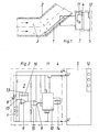
- Fig. 1 shows a piezoelectric dust sensor (1), in particular in a flow path in the angled connecting piece (2) of the floor nozzle of a vacuum cleaner, not shown is arranged.
- the dust particles moving through the floor nozzle (3) meet in the area of the pipe bend of the connection piece (2) on the one attached there piezoelectric dust sensor (1).
- the kinetic energy or the change in momentum of the The sensor converts dust particles (3) into a corresponding electrical signal.
- This so-called Charge signal (L) is fed via a line branch (4) to a signal evaluation circuit (5), whose operating voltage (battery voltage U of a battery 6) via an upstream Power supply circuit (7) is applied.
- the power supply circuit (7) with the dust sensor (1) is constantly connected to the battery, sh. also Fig. 2.
- Fig. 2 shows a simple block diagram of the signal evaluation circuit (5), which after Formation and function of a measuring circuit shown in EP 0 759 157 A1 corresponds.
- the known circuit is also battery-powered.
- Power supply circuit (7) with the dust sensor (1) for the signal evaluation circuit (5) is designed as a power switch and switches the signal evaluation circuit (5) in the case of dust particle sensing on the battery voltage (U) and in the de-energized Standby mode if no dust particles (3) are sensed.
- the power supply is switched off causes.
- the power supply is switched on and off from the amplitude values the charge signals (L) of the dust sensor (1) controlled depending on what threshold values or Sensitivity settings of the following amplifiers can be adjusted.
- Switching on and off the battery voltage (U) to the signal evaluation circuit (5) is a function of time or occurrence of the successive charge signals (L) of the piezoelectric dust sensor (1) dependent.
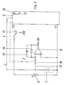
- These charge or trigger signals (L) are both the signal evaluation circuit (5), and separately via a feed line (17) that shown in Fig. 2 Power supply circuit (7) supplied.
- the dust sensor (1) is constantly on battery voltage (U) arranged power supply circuit (7) arranged, the power supply circuit (7) a charge signal amplifier (8) with a downstream comparator (9) for the preparation of the dust sensor via the line branch (4) or the feed line (17) (1) coming charge signals (L) includes.
- the processed charge signals (L) are fed to a monostable multivibrator (10), the output of which is the battery voltage (U) on the signal evaluation circuit (5) applying transistor (11) on and off.
- the charge signals (L) coming via the line branch (4) are also the Signal evaluation circuit (5) supplied, which ultimately via an associated display (12) informs the operator of the suction result when vacuuming.
- the operator display (12) can provide information on the respective dust particle level acoustically or optically.
- the charge signal amplifier (8) detects depending on the sensitivity - adjustable by a transverse capacitance (13) and a transverse resistor (16) - the operating noise of the vacuum cleaner and impinging dust particles (3).
- the comparator (9) forms the noisy output signal of the Charge signal amplifier (8) in rectangular signal blocks, whereupon this the monostable multivibrator (10) trigger.
- the monostable multivibrator (10) switches for via its resistor / capacitor combination (14) set time (e.g. about 1 second) the transistor (11), whereupon the battery voltage (U) is switched through to the signal evaluation circuit (5) becomes. As long as the dust sensor (1) delivers signals, the flip-flop (10) is always on triggered so that the operating time starts all over again.
- the voltage to the signal evaluation circuit (5) is preferably within about 1 second interrupted.
- the reset time of the monostable multivibrator (10) of the power supply circuit (7) can be changed by changing the resistance / capacitor values from (14) can be varied.
- Via a voltage divider (15) connected to the battery voltage (U) is the sensitivity (switching threshold) of the amplified charge signals (L) (or trigger signals) adjustable.
- the charge signal amplifier (8) leading supply line (17) branching off from the line branch (4) also a decoupling switch (18) can be placed by the electronics of the vacuum cleaner is operated.
- This switch (18) could be a transistor or a relay contact. In standby mode the switch (18) is closed. If dust signals are received, the Comparator (9) the monoflop and thus the display (12) for the first time for approx. 1 to 2 seconds switched on.
- the switch (18) opens and the sensor signals (L) are decoupled from the charge amplifier (8). After the expiration of the "Single phase” switches the monoflop (10) the battery-supplied signal evaluation circuit (5) again out. The switch (18) closes again and the triggering starts again.
- the switch in the line branch (4) or both Lines (4, 17) to be provided with switches (18).
- a quiescent current consumption determined in the experiment with the circuit arrangement according to the invention gave a current value of approx. 70 microamps at 6 volt battery voltage.
- the charge signal amplifier of the power supply circuit was advantageous as a multiple operational amplifier (e.g. dual amplifier).
- four 1.5 V Mignon cells with a capacity of approx. 2 Ah and an effective suction time with the vacuum cleaner of 50 hours / year, with an average current consumption of 30 mA depending on the number the indicator lamps of the switched-on display device of the signal evaluation circuit battery life is around 1.5 years.
- the low power consumption of the power supply circuit (7) of about 70 microamps results from the use of low or micro power semiconductors in the circuit.
- the invention enables the implementation of inexpensive electronics which save space and also possibly location-independent in a vacuum cleaner or its floor nozzle, e.g. B. also in Handle to be installed. Due to the "power switch function" of the Power supply circuit (7) for the signal evaluation circuit (5) is a long battery life possible in standby mode. Instead of a piezoelectric dust sensor (1) could also be a photoelectric or optoelectronic dust sensor if the circuit is adapted be used. In addition, the invention can of course also be applied other battery operated electronic circuits with sensors that apply signals generated that can be used for triggering.
Landscapes
- Engineering & Computer Science (AREA)
- Chemical & Material Sciences (AREA)
- Chemical Kinetics & Catalysis (AREA)
- Electrochemistry (AREA)
- General Chemical & Material Sciences (AREA)
- Mechanical Engineering (AREA)
- Microelectronics & Electronic Packaging (AREA)
- Manufacturing & Machinery (AREA)
- Electric Vacuum Cleaner (AREA)
- Charge And Discharge Circuits For Batteries Or The Like (AREA)
Applications Claiming Priority (2)
| Application Number | Priority Date | Filing Date | Title |
|---|---|---|---|
| DE10204070A DE10204070A1 (de) | 2002-02-01 | 2002-02-01 | Verfahren und Schaltungsanordnung zur Vermeidung der Standby-Entladung einer batterieversorgten Signal-Auswerteschaltung für einen Sensor |
| DE10204070 | 2002-02-01 |
Publications (2)
| Publication Number | Publication Date |
|---|---|
| EP1333555A2 true EP1333555A2 (fr) | 2003-08-06 |
| EP1333555A3 EP1333555A3 (fr) | 2006-07-12 |
Family
ID=7713524
Family Applications (1)
| Application Number | Title | Priority Date | Filing Date |
|---|---|---|---|
| EP02027108A Withdrawn EP1333555A3 (fr) | 2002-02-01 | 2002-12-04 | Procédé et circuit pour éviter la discharge en mode de veille d'un circuit d'évaluation de signal alimenté par batterie |
Country Status (3)
| Country | Link |
|---|---|
| US (1) | US6801015B2 (fr) |
| EP (1) | EP1333555A3 (fr) |
| DE (1) | DE10204070A1 (fr) |
Cited By (1)
| Publication number | Priority date | Publication date | Assignee | Title |
|---|---|---|---|---|
| EP3482667A1 (fr) * | 2017-11-13 | 2019-05-15 | LG Electronics Inc. | Module de capteur de poussière et son procédé de fonctionnement |
Families Citing this family (5)
| Publication number | Priority date | Publication date | Assignee | Title |
|---|---|---|---|---|
| US6956348B2 (en) | 2004-01-28 | 2005-10-18 | Irobot Corporation | Debris sensor for cleaning apparatus |
| US20020106308A1 (en) * | 2001-02-02 | 2002-08-08 | Zweifel Ronald A. | Microdrop dispensing apparatus |
| DE102004007677B4 (de) * | 2004-02-16 | 2011-11-17 | Miele & Cie. Kg | Saugdüse für einen Staubsauger mit einer Staubfluss-Anzeigevorrichtung |
| EP2659260B1 (fr) | 2010-12-30 | 2019-11-20 | iRobot Corporation | Surveillance de détritus |
| KR102945800B1 (ko) | 2020-02-04 | 2026-03-27 | 엘지전자 주식회사 | 청소기 |
Family Cites Families (9)
| Publication number | Priority date | Publication date | Assignee | Title |
|---|---|---|---|---|
| US4782241A (en) * | 1987-08-11 | 1988-11-01 | Liebert Corporation | Uninterruptible power supply apparatus and power path transfer method |
| DE4425291A1 (de) * | 1994-05-10 | 1995-11-16 | Heinrich Dr Ing Iglseder | Verfahren zum Nachweis von Partikeln in einer 2-Phasen-Strömung, Staubsauger sowie Verfahren zum Steuern oder Regeln eines Staubsaugers |
| HUT75482A (en) | 1994-05-10 | 1997-05-28 | Iglseder | Method of detecting particles in a two-phase stream, vacuum cleaner and a method of controlling or adjusting a vacuum cleaner |
| JP3351637B2 (ja) * | 1994-10-07 | 2002-12-03 | アイワ株式会社 | 電力増幅回路 |
| JPH09135127A (ja) * | 1995-11-07 | 1997-05-20 | Nec Corp | 電力増幅器 |
| EP0845237B1 (fr) * | 1996-11-29 | 2000-04-05 | YASHIMA ELECTRIC CO., Ltd. | Aspirateur |
| EP1032964A2 (fr) * | 1997-11-17 | 2000-09-06 | Lifestyle Technologies | Systeme d'alimentation polyvalent |
| DE19846103A1 (de) | 1998-10-07 | 2000-04-20 | Vorwerk Co Interholding | Staubsauger |
| US6340879B1 (en) * | 1999-02-03 | 2002-01-22 | Nokia Mobile Phones Ltd. | Device for reactivating an electric battery |
-
2002
- 2002-02-01 DE DE10204070A patent/DE10204070A1/de not_active Ceased
- 2002-12-04 EP EP02027108A patent/EP1333555A3/fr not_active Withdrawn
-
2003
- 2003-01-16 US US10/345,687 patent/US6801015B2/en not_active Expired - Fee Related
Cited By (2)
| Publication number | Priority date | Publication date | Assignee | Title |
|---|---|---|---|---|
| EP3482667A1 (fr) * | 2017-11-13 | 2019-05-15 | LG Electronics Inc. | Module de capteur de poussière et son procédé de fonctionnement |
| KR20190054326A (ko) * | 2017-11-13 | 2019-05-22 | 엘지전자 주식회사 | 먼지 센서 모듈 및 그의 동작 방법 |
Also Published As
| Publication number | Publication date |
|---|---|
| US20030146739A1 (en) | 2003-08-07 |
| DE10204070A1 (de) | 2003-08-14 |
| EP1333555A3 (fr) | 2006-07-12 |
| US6801015B2 (en) | 2004-10-05 |
Similar Documents
| Publication | Publication Date | Title |
|---|---|---|
| EP3119260A1 (fr) | Procédé pour nettoyer un filtre d'un appareil d'aspiration des poussières, et appareil d'aspiration des poussières | |
| EP2672870B1 (fr) | Méthode pour nettoyer un filtre d'un aspirateur et l'aspirateur pour la mise en pratique de la méthode. | |
| EP1519673B8 (fr) | Procede pour faire fonctionner un systeme de nettoyage de sol, et systeme de nettoyage de sol fonctionnant selon ce procede | |
| WO2012031925A1 (fr) | Dispositif et procédé pour détecter un changement d'état de fonctionnement d'un outil électrique ainsi qu'un aspirateur | |
| EP1148805A1 (fr) | Systeme de mesure pour controler la poussiere residuelle pour aspirateurs de securite | |
| EP3127461B1 (fr) | Procede de fonctionnement d'un appareil d'aspiration pour surfaces dures et appareil d'aspiration pour surfaces dures destine a executer le procede | |
| DE2642633A1 (de) | Feststellvorrichtung | |
| EP1333555A2 (fr) | Procédé et circuit pour éviter la discharge en mode de veille d'un circuit d'évaluation de signal alimenté par batterie | |
| DE102012107994A1 (de) | Verfahren zum Betreiben eines tragbaren Hartflächenabsauggeräts und Hartflächenabsauggerät zur Durchführung des Verfahrens | |
| EP2595522B1 (fr) | Procédé et dispositif de commande de performance d'un moteur de soufflerie pour un aspirateur | |
| DE102010038577B4 (de) | Vorrichtung und Verfahren zum Betreiben eines Staubsaugers | |
| EP2091764B1 (fr) | Système de détection du mouvement d'une roue | |
| DE19603553C1 (de) | Vorrichtung zum Betreiben eines Scheibenwischers | |
| EP1877740A2 (fr) | Procede et dispositif pour diagnostiquer des composantes mecaniques, electromecaniques ou fluidiques | |
| DE102011006539B4 (de) | Staubsauger und Verfahren zum betriebsdauerabhängigen Betreiben eines Staubsaugers | |
| EP1873511A2 (fr) | Arrangement d'un filtre de particules et un capteur pour la détermination des concentrations de particules conductrices dans des gaz | |
| EP2076635B1 (fr) | Procédé et dispositif pour détecter l'utilisation d'urinoirs et déclencher un rinçage automatique | |
| EP1339923B1 (fr) | Dispositif de chasse sans contact pour w.-c., et procede d'actionnement sans contact d'une chasse de w.-c. | |
| EP1359408B1 (fr) | Dispositif et méthode pour la détection de condensation sur une surface de mesure | |
| DE102021111734A1 (de) | Diagnosefähige Schaltungsanordnung und Verfahren zur Diagnose einer Schaltungsanordnung | |
| DE102014100580A1 (de) | Vorrichtung zum berührungslosen Betätigen einer Schiebetür eines Kraftfahrzeuges | |
| DE102009025396B4 (de) | Vorrichtung zum Erfassen und Übertragen eines Messwerts, Reihenschaltung, System zum Erfassen und Übertragen von Messwerten und Haushaltsgerät | |
| DE102018214450A1 (de) | Impedanzerkennung eines Verbrauchers an einer Ladestation | |
| DE102011079118B4 (de) | Staubsauger | |
| DE102007033152A1 (de) | Verfahren und Vorrichtung zur Diagnose einer Ausgangsgröße eines Gleichstrommotors |
Legal Events
| Date | Code | Title | Description |
|---|---|---|---|
| PUAI | Public reference made under article 153(3) epc to a published international application that has entered the european phase |
Free format text: ORIGINAL CODE: 0009012 |
|
| AK | Designated contracting states |
Designated state(s): AT BE BG CH CY CZ DE DK EE ES FI FR GB GR IE IT LI LU MC NL PT SE SI SK TR |
|
| AX | Request for extension of the european patent |
Extension state: AL LT LV MK RO |
|
| PUAL | Search report despatched |
Free format text: ORIGINAL CODE: 0009013 |
|
| AK | Designated contracting states |
Kind code of ref document: A3 Designated state(s): AT BE BG CH CY CZ DE DK EE ES FI FR GB GR IE IT LI LU MC NL PT SE SI SK TR |
|
| AX | Request for extension of the european patent |
Extension state: AL LT LV MK RO |
|
| RIC1 | Information provided on ipc code assigned before grant |
Ipc: A47L 9/28 20060101ALI20060608BHEP Ipc: H03F 1/02 20060101AFI20060608BHEP |
|
| AKX | Designation fees paid | ||
| STAA | Information on the status of an ep patent application or granted ep patent |
Free format text: STATUS: THE APPLICATION IS DEEMED TO BE WITHDRAWN |
|
| 18D | Application deemed to be withdrawn |
Effective date: 20070116 |
|
| REG | Reference to a national code |
Ref country code: DE Ref legal event code: 8566 |