EP1335354A2 - Méthode de transfert magnétique - Google Patents
Méthode de transfert magnétique Download PDFInfo
- Publication number
- EP1335354A2 EP1335354A2 EP03002683A EP03002683A EP1335354A2 EP 1335354 A2 EP1335354 A2 EP 1335354A2 EP 03002683 A EP03002683 A EP 03002683A EP 03002683 A EP03002683 A EP 03002683A EP 1335354 A2 EP1335354 A2 EP 1335354A2
- Authority
- EP
- European Patent Office
- Prior art keywords
- magnetic field
- slave medium
- magnetic
- transfer
- initial
- Prior art date
- Legal status (The legal status is an assumption and is not a legal conclusion. Google has not performed a legal analysis and makes no representation as to the accuracy of the status listed.)
- Pending
Links
- 238000000034 method Methods 0.000 title claims description 42
- 230000005415 magnetization Effects 0.000 description 17
- 230000000052 comparative effect Effects 0.000 description 16
- 239000000969 carrier Substances 0.000 description 10
- 230000000694 effects Effects 0.000 description 2
- 238000005516 engineering process Methods 0.000 description 1
- 230000004907 flux Effects 0.000 description 1
- 238000004804 winding Methods 0.000 description 1
Images

Classifications
-
- G—PHYSICS
- G11—INFORMATION STORAGE
- G11B—INFORMATION STORAGE BASED ON RELATIVE MOVEMENT BETWEEN RECORD CARRIER AND TRANSDUCER
- G11B5/00—Recording by magnetisation or demagnetisation of a record carrier; Reproducing by magnetic means; Record carriers therefor
- G11B5/86—Re-recording, i.e. transcribing information from one magnetisable record carrier on to one or more similar or dissimilar record carriers
-
- G—PHYSICS
- G11—INFORMATION STORAGE
- G11B—INFORMATION STORAGE BASED ON RELATIVE MOVEMENT BETWEEN RECORD CARRIER AND TRANSDUCER
- G11B5/00—Recording by magnetisation or demagnetisation of a record carrier; Reproducing by magnetic means; Record carriers therefor
- G11B5/86—Re-recording, i.e. transcribing information from one magnetisable record carrier on to one or more similar or dissimilar record carriers
- G11B5/865—Re-recording, i.e. transcribing information from one magnetisable record carrier on to one or more similar or dissimilar record carriers by contact "printing"
-
- G—PHYSICS
- G11—INFORMATION STORAGE
- G11B—INFORMATION STORAGE BASED ON RELATIVE MOVEMENT BETWEEN RECORD CARRIER AND TRANSDUCER
- G11B5/00—Recording by magnetisation or demagnetisation of a record carrier; Reproducing by magnetic means; Record carriers therefor
- G11B5/012—Recording on, or reproducing or erasing from, magnetic disks
Definitions
- This invention relates to a method of magnetic transfer for transferring information to a magnetic recording medium (slave medium) from a master information carrier carrying thereon a magnetic layer pattern representing the information to be transferred to the magnetic recording medium.
- a magnetic recording medium which is high in capacity, low in cost and preferably requires a short time to read out a necessary part of data (a magnetic recording medium which allows so-called high-speed access).
- a magnetic recording medium which allows so-called high-speed access.
- a high recording density magnetic medium such as a hard disc or a flexible disc.
- so-called servo tracking technology for causing a magnetic head to accurately trace narrow data tracks plays an important role.
- servo information (a servo tracking signal, an address information signal, a reproduction clock signal and the like) is recorded on the disc as so-called preformat.
- a master information carrier having thereon an irregularity pattern (a pattern of protruding portions and recessed portions) representing information (e.g., servo information) to be transferred to a slave medium (a magnetic recording medium such as a magnetic disc) and a magnetic layer formed at least on the protruding portions is brought into a close contact with the slave medium and a transfer magnetic field is applied to the master information carrier and the slave medium in a close contact with each other, whereby a magnetization pattern corresponding to the information represented by the irregularity pattern is magnetically transferred from the master information carrier to the slave medium.
- the information carried by the master information carrier can be statically recorded on the slave medium with the relative position between the master information carrier and the slave medium kept constant.
- the preformat recording can be performed accurately and the time required for the preformat recording is very short.
- the method using such a magnetic field applying apparatus gives rise to a problem that when rotation of the slave medium is stopped (to end the magnetic transfer) in the magnetic field applied, turbulence of the magnetization is generated due to leakage of the magnetic field in the area of the slave medium to which the magnetic field is applied upon stopping of rotation of the slave medium, which results in noise.
- the primary object of the present invention is to provide an improved method of magnetic transfer which suppresses the influence of the leakage magnetic field upon termination of magnetic transfer and enables to obtain a good reproduction signal high in CN ratio from a transferred slave medium.
- a method of magnetic transfer for magnetically transferring information represented by a pattern of magnetic layer formed on a master information carrier to a magnetic layer of a disc-like slave medium comprising the steps of applying an initial DC magnetic field to the slave medium to initially magnetize the magnetic layer of the slave medium in one direction of concentric recording tracks and applying a transfer magnetic field to the slave medium in the direction opposite to the direction of the initial-magnetization with the initially-magnetized magnetic layer of the slave medium held in close contact with the magnetic layer on the master information carrier, wherein the improvement comprises that at least one of applying the initial DC magnetic field and applying the transfer magnetic field is effected by applying the magnetic field while the slave medium is being rotated relatively to the magnetic field and stopping the rotation of the slave medium after the intensity of the magnetic field is gradually reduced to not stronger than a predetermined value.
- Concentric recording tracks means recording tracks to be formed on the slave medium by magnetic transfer.
- to transfer information means to pattern the arrangement of magnetization of the magnetic layer of the slave medium according to the information.
- the expression "the initially-magnetized magnetic layer of the slave medium held in close contact with the magnetic layer on the master information carrier" should be interpreted not only to mean a state where the former is in contact with the latter but also to mean a state where the former is held in the vicinity of the latter uniformly spaced from each other.
- the magnetic layer of the slave medium may be initially magnetized either in a state where the slave medium is in close contact with the master information carrier or in a state where the slave medium is held away from the master information carrier. In the latter case, the slave medium is brought into close contact with the master information carrier after initial magnetization.
- the intensity of the initial DC magnetic field is preferably not lower than the coercive force of the magnetic layer of the slave medium and more preferably not lower than 1.2 times the coercive force of the magnetic layer of the slave medium.
- the intensity of the transfer magnetic field is preferably not lower than about 0.6 times the coercive force of the magnetic layer of the slave medium and not higher than about 1.3 times the coercive force of the magnetic layer of the slave medium.
- the rotational speed of the slave medium is about several rpm to about several hundred rpm.
- the intensity of the magnetic field as mentioned here means that as measured on the surface of the slave medium.
- “to reduce the intensity of the magnetic field” means to reduce the intensity of the magnetic field as measured on the surface of the slave medium.
- the intensity of the magnetic field can be reduced either by reducing the magnetic field generated by the electromagnet or by moving the electromagnet away from the slave medium. When the electromagnet is moved away from the slave medium, the electromagnet should be moved in the direction in which the orientation of the magnetic flux on the surface of the slave medium is not changed.
- the "predetermined value” is such a value at which the magnetic field cannot affect magnetization of the slave medium, and may be, for instance, not higher than about 1/10 of the preferable range of the intensity of the magnetic field.
- the slave medium may be rotated relatively to the magnetic field either by rotating the slave medium or by rotating the magnetic field.
- turbulence of the magnetization is prevented from being generated due to leakage of the magnetic field from the electromagnet or the like upon stopping rotation of the slave medium in the applied magnetic field, whereby a good reproduction signal can be obtained from the slave medium after magnetic transfer.
- the procedure of applying the magnetic field while the slave medium is being rotated relatively to the magnetic field and stopping the rotation of the slave medium after the intensity of the magnetic field is gradually reduced to not stronger than a predetermined value may be effected when one of the initial DC magnetic field and the transfer magnetic field is applied to the slave medium, a better effect can be obtained when the procedure of applying the magnetic field while the slave medium is being rotated relatively to the magnetic field and stopping the rotation of the slave medium after the intensity of the magnetic field is gradually reduced to not stronger than a predetermined value is effected both when the initial DC magnetic field is applied to the slave medium and when the transfer magnetic field is applied to the slave medium.
- a method of magnetic transfer for magnetically transferring information represented by a pattern of magnetic layer formed on a master information carrier to a magnetic layer of a disc-like slave medium comprising the steps of applying an initial DC magnetic field to the slave medium to initially magnetize the magnetic layer of the slave medium in one direction of concentric recording tracks and applying a transfer magnetic field to the slave medium in the direction opposite to the direction of the initial-magnetization with the initially-magnetized magnetic layer of the slave medium held in close contact with the magnetic layer on the master information carrier, wherein the improvement comprises that at least one of applying the initial DC magnetic field and applying the transfer magnetic field is effected by applying a magnetic field to a part of the slave medium while the slave medium is being rotated relatively to the magnetic field and moving the slave medium relatively to the magnetic field so that the center of the slave medium is moved away from the magnetic field in a radial direction with the slave medium kept rotated.
- the intensity of the magnetic field be gradually reduced to not stronger than a predetermined value while moving the slave medium relatively to the magnetic field so that the center of the slave medium is moved away from the magnetic field in a radial direction in at least one of applying the initial DC magnetic field and applying the transfer magnetic field.
- Concentric recording tracks means recording tracks to be formed on the slave medium by magnetic transfer.
- to transfer information means to pattern the arrangement of magnetization of the magnetic layer of the slave medium according to the information.
- the expression "the initially-magnetized magnetic layer of the slave medium held in close contact with the magnetic layer on the master information carrier" should be interpreted not only to mean a state where the former is in contact with the latter but also to mean a state where the former is held in the vicinity of the latter uniformly spaced from each other.
- the magnetic layer of the slave medium may be initially magnetized either in a state where the slave medium is in close contact with the master information carrier or in a state where the slave medium is held away from the master information carrier. In the latter case, the slave medium is brought into close contact with the master information carrier after initial magnetization.
- the intensity of the initial DC magnetic field is preferably not lower than the coercive force of the magnetic layer of the slave medium and more preferably not lower than 1.2 times the coercive force of the magnetic layer of the slave medium.
- the intensity of the transfer magnetic field is preferably not lower than about 0.6 times the coercive force of the magnetic layer of the slave medium and not higher than about 1.3 times the coercive force of the magnetic layer of the slave medium.
- the rotational speed of the slave medium is about several rpm to about several hundred rpm.
- the slave medium may be moved relatively to the magnetic field either by moving one of the slave medium and the magnetic field or by moving both the slave medium and the magnetic field.
- the initial DC magnetic field and the transfer magnetic field may be generated either by an electromagnet unit or by a permanent magnet unit.
- turbulence of the magnetization is prevented from being generated due to leakage of the magnetic field from the electromagnet or the like upon stopping rotation of the slave medium in the applied magnetic field, whereby a good reproduction signal can be obtained from the slave medium after magnetic transfer.
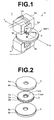
- a pair of pieces of information are transferred to opposite sides of a slave medium (magnetic recording medium) 2 by a method of magnetic transfer in accordance with an embodiment of the present invention from a pair of master information carriers 3 and 4.
- the magnetic transfer apparatus shown in Figure 1 comprises an electromagnet unit 5 having upper and lower electromagnets 5a and 5b, and a holder 8 which is disposed between the upper and lower electromagnets 5a and 5b and is rotated in the direction of arrow A by a drive means (not shown) .
- the holder 8 is like a disc in shape and comprises upper and lower discs.
- an initial DC magnetic field is applied to the slave medium 2
- the slave medium 2 is held between the upper and lower discs of the holder 8
- a transfer magnetic field is applied to the slave medium 2
- the slave medium 2 and the master information carriers 3 and 4 in close contact with the respective sides of the slave medium 2 are held between the upper and lower discs of the holder 8. Accordingly, to rotate the holder 8 is equivalent to rotate the slave medium 2 or to rotate the slave medium 2 and the master information carriers 3 and 4 in close contact with the slave medium 2.
- the slave medium 2 is a disc-like magnetic recording medium such as a hard disc, a flexible disc or the like.
- the slave medium 2 shown in Figure 2 is a double-sided magnetic recording medium comprising a disc-like base sheet 2a and magnetic layers 2b and 2c formed on opposite sides of the base sheet 2a.
- the master information carriers 3 and 4 are like a disc in shape and comprises base sheets 3a and 4a having on their one sides irregularity patterns representing information to be transferred to the magnetic layers 2b and 2c of the magnetic recording media (slave media) and soft magnetic layers 3b and 4b provided on the surface of the base sheets 3a and 4a.
- the irregularity patterns respectively carried by the master information carriers 3 and 4 represent information to be transferred to the lower magnetic layer 2b and the upper magnetic layer 2c.
- the magnetic layers 3b and 4b of the master information carriers 3 and 4 are brought into close contact with the lower and upper magnetic layers 2b and 2c with the other sides held by the lower and upper discs of the holder 8.
- the information carried by the master information carriers 3 and 4 may be transferred to opposite sides of the slave medium 2 either simultaneously or in sequence.
- Each of the upper and lower electromagnets 5a and 5b of the electromagnet unit 5 comprises a core 52 having a gap 51 which radially extends from a minimum radius track r min to a maximum radius track r max of the slave medium 2 and a winding 53 wound around the core 52, and the upper and lower electromagnets 5a and 5b generate magnetic fields having magnetic lines of force parallel to the direction of the tracks in the same directions on opposite sides of the slave medium 2. It is not necessary to provide an electromagnet on each side of the slave medium but an electromagnet may be provided only on one side of the slave medium 2.
- the magnetic field is applied to the entire area of the tracks while rotating the holder 8 holding the slave medium 2 or the slave medium 2 and the master information carrier 3 and/or 4 in close contact with the slave medium 2 relatively to the magnetic field.
- the gap 51 of each of the electromagnets 5a and 5b extends from the minimum radius track r min to the maximum radius track r max of the slave medium 2, a uniform magnetic field can be applied to the entire area of the tracks by once rotating the slave medium 2 about the electromagnets 5a and 5b.
- the slave medium 2 is moved radially moved relatively to the electromagnets 5a and 5b while rotated about the electromagnets 5a and 5b.
- the slave medium 2 is set between the upper and lower discs of the holder 8 and the holder 8 together with the slave medium 2 is positioned in place between the upper and lower electromagnets 5a and 5b of the electromagnet units 5 generating an initial DC magnetic field Hin in the direction of the arrow in Figure 3A, thereby magnetizing the magnetic layers 2b and 2c of the slave medium 2 in an initial DC magnetization as shown in Figure 3A.
- the holder 8 is positioned so that the longitudinal direction of the electromagnets 5a and 5b conforms to a radial direction of the holder 8. Thereafter, the holder 8 is caused to make one rotation relatively to the electromagnets 5a and 6b in the direction arrow A ( Figure 1).
- the intensity of the magnetic field generated by the electromagnets 5a and 5b is gradually reduced.
- rotation of the holder 8 is stopped and the holder 8 is removed from between the upper and lower electromagnets 5a and 5b.
- the intensity of the initial DC magnetic field is preferably not lower than the coercive force Hcs of the magnetic layer of the slave medium 2 and more preferably not lower than 1.2 times the coercive force Hcs of the magnetic layer of the slave medium 2.
- the "predetermined value" is, for instance, not higher than about 1/10 of the intensity of the initial DC magnetic field but may be any value so long as the initial DC magnetic field cannot affect magnetization of the slave medium 2.
- the magnetic layer 3b of the lower master information carrier 3 and the magnetic layer 4b of the upper master information carrier 4 are brought into close contact with the lower and upper magnetic layers 2b of the slave medium 2 by the holder 8 .
- the holder 8 together with the slave medium 2 and the master information carriers 3 and 4 in close contact with opposite sides of the slave medium 2 is positioned in place between the upper and lower electromagnets 5a and 5b of the electromagnet units 5 generating a transfer magnetic field Hdu in a direction opposite to the initial DC magnetic field as shown in Figure 3B.
- the holder 8 is positioned so that the longitudinal direction of the electromagnets 5a and 5b conforms to a radial direction of the holder 8.
- the holder 8 is caused to make one rotation relatively to the electromagnets 5a and 6b in the direction arrow A ( Figure 1), thereby effecting magnetic transfer.
- the intensity of the magnetic field generated by the electromagnets 5a and 5b is gradually reduced.
- rotation of the holder 8 is stopped and the holder 8 is removed from between the upper and lower electromagnets 5a and 5b.
- the intensity of the transfer magnetic field Hdu is preferably 0.6 times to 1.3 times the coercive force Hcs of the magnetic layer of the slave medium 2, more preferably 0.8 to 1.2 times the coercive force Hcs of the magnetic layer of the slave medium 2, and most preferably 1 to 1.1 times the coercive force Hcs of the magnetic layer of the slave medium 2.
- the "predetermined value" is, for instance, not higher than about 1/10 of the intensity of the transfer magnetic field but may be any value so long as the transfer magnetic field cannot affect magnetization of the slave medium 2.
- the intensity of the magnetic field applied to the slave medium 2 may be reduced by moving the electromagnets 5a and 5b away from the surface of the slave medium 2 in perpendicular to the surface of the slave medium 2 so that the magnetic field is moved away from the surface of the slave medium 2.
- permanent magnets can be employed in place of the electromagnets 5a and 5b.
- the information can be magnetically transferred to the slave medium 2 by reversing the directions of the initial DC magnetic field Hin and the transfer magnetic field Hdu.
- the slave medium was 278.8kA/m (3500Oe) in coercive force
- the intensity of the initial DC magnetic field Hin was 557.2kA/m (7000Oe)
- the distance between the tip of the magnetic pole and the surface of the slave medium when applying the initial DC magnetic field was 2.5mm
- the intensity of the transfer magnetic field Hdu was 278.8kA/m (3500Oe)
- the distance between the tip of the magnetic pole and the surface of the slave medium when applying the transfer magnetic field was 10mm
- the contact pressure between the slave medium and the master information carrier was 2Kg/cm 2 .
- the holder was inserted into the magnetic field, rotated, stopped after rotated by an amount equal to or more than one rotation, and then drawn out from the magnetic field both when the initial DC magnetic field was applied and when the transfer magnetic field was applied.
- the initial DC magnetic field was applied by inserting the holder into the magnetic field, rotating the holder at 60rpm, gradually reducing the intensity of the magnetic field at a rate of 8.0kA/Sec (100Oe/Sec) with the holder kept rotated at 60rpm after rotated by an amount equal to or more than one rotation, stopping rotation of the holder when the intensity of the magnetic field was reduced to 0, and then removing the holder.
- the transfer magnetic field was applied in the same manner as in the comparative example.
- the initial DC magnetic field was applied by inserting the holder into the magnetic field, rotating the holder at 600rpm, gradually reducing the intensity of the magnetic field at a rate of 39.8kA/Sec (500Oe/Sec) with the holder kept rotated at 600rpm after rotated by an amount equal to or more than one rotation, stopping rotation of the holder when the intensity of the magnetic field was reduced to 0, and then removing the holder.
- the transfer magnetic field was applied in the same manner as in the comparative example.
- the initial DC magnetic field was applied in the same manner as in the comparative example.
- the transfer magnetic field was applied by inserting the holder into the magnetic field, rotating the holder at 60rpm, gradually reducing the intensity of the magnetic field at a rate of 8.0kA/Sec (100Oe/Sec) with the holder kept rotated at 60rpm after rotated by an amount equal to or more than one rotation, stopping rotation of the holder when the intensity of the magnetic field was reduced to 0, and then removing the holder.
- the initial DC magnetic field was applied in the same manner as in the comparative example.
- the transfer magnetic field was applied by inserting the holder into the magnetic field, rotating the holder at 600rpm, gradually reducing the intensity of the magnetic field at a rate of 39.8kA/Sec (500Oe/Sec) with the holder kept rotated at 600rpm after rotated by an amount equal to or more than one rotation, stopping rotation of the holder when the intensity of the magnetic field was reduced to 0, and then removing the holder.
- the initial DC magnetic field the transfer magnetic field were applied by inserting the holder into the magnetic field, rotating the holder at 60rpm, gradually reducing the intensity of the magnetic field at a rate of 8.0kA/Sec (1000e/Sec) with the holder kept rotated at 60rpm after rotated by an amount equal to or more than one rotation, stopping rotation of the holder when the intensity of the magnetic field was reduced to 0, and then removing the holder.
- the initial DC magnetic field the transfer magnetic field were applied by inserting the holder into the magnetic field, rotating the holder at 600rpm, gradually reducing the intensity of the magnetic field at a rate of 39.8kA/Sec (5000e/Sec) with the holder kept rotated at 600rpm after rotated by an amount equal to or more than one rotation, stopping rotation of the holder when the intensity of the magnetic field was reduced to 0, and then removing the holder.
- the procedure of applying the magnetic field while the slave medium is being rotated relatively to the magnetic field and stopping the rotation of the slave medium after the intensity of the magnetic field is gradually reduced to not stronger than a predetermined value is more effective when executed upon application of the initial DC magnetic field than when executed upon application of the transfer magnetic field.
- the fifth and sixth embodiments indicate that a better result can be obtained when the procedure of applying the magnetic field while the slave medium is being rotated relatively to the magnetic field and stopping the rotation of the slave medium after the intensity of the magnetic field is gradually reduced to not stronger than a predetermined value is effected both when the initial DC magnetic field is applied to the slave medium and when the transfer magnetic field is applied to the slave medium.
- the slave medium 2 is set between the upper and lower discs of the holder 8 and the holder 8 together with the slave medium 2 is positioned in place between the upper and lower electromagnets 5a and 5b of the electromagnet units 5 generating an initial DC magnetic field Hin in the direction of the arrow in Figure 3A, thereby magnetizing the magnetic layers 2b and 2c of the slave medium 2 in an initial DC magnetization as shown in Figure 3A.
- the holder 8 is positioned so that the longitudinal direction of the electromagnets 5a and 5b conforms to a radial direction of the holder 8. Thereafter, the holder 8 is caused to make one rotation relatively to the electromagnets 5a and 6b in the direction arrow A ( Figure 1).
- the slave medium is moved relatively to the magnetic field in the direction of arrow X ( Figure 1) so that the center M of the holder 8 (i.e., the center of the slave medium 2) is moved away from the magnetic field in a radial direction with the holder 8 kept rotated.
- the holder 8 is moved to a position where the influence of the magnetic field on magnetization of the slave medium 2 is sufficiently small, rotation of the holder 8 is stopped.
- the intensity of the initial DC magnetic field Hin is preferably not lower than the coercive force Hcs of the magnetic layer of the slave medium 2 and more preferably not lower than 1.2 times the coercive force Hcs of the magnetic layer of the slave medium 2.
- the magnetic layer 3b of the lower master information carrier 3 and the magnetic layer 4b of the upper master information carrier 4 are brought into close contact with the lower and upper magnetic layers 2b of the slave medium 2 by the holder 8.
- the holder 8 together with the slave medium 2 and the master information carriers 3 and 4 in close contact with opposite sides of the slave medium 2 is positioned in place between the upper and lower electromagnets 5a and 5b of the electromagnet units 5 generating a transfer magnetic field Hdu in a direction opposite to the initial DC magnetic field as shown in Figure 3B.
- the holder 8 is positioned so that the longitudinal direction of the electromagnets 5a and 5b conforms to a radial direction of the holder 8.
- the holder 8 is caused to make one rotation relatively to the electromagnets 5a and 6b in the direction arrow A ( Figure 1), thereby effecting magnetic transfer.
- the slave medium After the holder 8 makes one rotation, the slave medium is moved relatively to the magnetic field in the direction of arrow X so that the center M of the holder 8 (i.e., the center of the slave medium 2) is moved away from the magnetic field in a radial direction with the holder 8 kept rotated. After the holder 8 is moved to a position where the influence of the magnetic field on magnetization of the slave medium 2 is sufficiently small, rotation of the holder 8 is stopped.
- the intensity of the transfer magnetic field Hdu is preferably 0.6 to 1.3 times the coercive force Hcs of the magnetic layer of the slave medium 2, more preferably 0.8 to 1.2 times the coercive force Hcs of the magnetic layer of the slave medium 2, and most preferably 1 to 1.1 times the coercive force Hcs of the magnetic layer of the slave medium 2.
- the slave medium is moved relatively to the magnetic field in the direction of arrow X after the holder 8 makes one rotation to move the center M of the holder 8 (i.e., the center of the slave medium 2) away from the magnetic field, instead the upper and lower magnets 5a and 5b may be moved in the direction of arrow Y ( Figure 1).
- the information can be magnetically transferred to the slave medium 2 by reversing the directions of the initial DC magnetic field Hin and the transfer magnetic field Hdu.
- the intensity of the magnetic field generated by the electromagnet units 5 is gradually reduced to not stronger than a predetermined value while moving the holder 8 relatively to the magnetic field in the radial direction X or moving the electromagnet units 5 in direction of arrow Y with the holder 8 kept rotated after the holder 8 is rotated once or more in the initial DC magnetic field and/or the transfer magnetic field.
- the "predetermined value” is such a value at which the magnetic field cannot affect magnetization of the slave medium 2, and may be, for instance, not higher than about 1/10 of the preferable range of the intensity of the initial DC magnetic field Hin or the transfer magnetic field Hdu.
- the slave medium was 278.8kA/m (3500Oe) in coercive force
- the intensity of the initial DC magnetic field Hin was 557.2kA/m (7000Oe)
- the distance between the tip of the magnetic pole and the surface of the slave medium when applying the initial DC magnetic field was 2.5mm
- the intensity of the transfer magnetic field Hdu was 278.8kA/m (3500Oe)
- the distance between the tip of the magnetic pole and the surface of the slave medium when applying the transfer magnetic field was 10mm
- the contact pressure between the slave medium and the master information carrier was 2Kg/cm 2 .
- the holder was inserted into the magnetic field, rotated, stopped after rotated by an amount equal to or more than one rotation, and then drawn out from the magnetic field both when the initial DC magnetic field was applied and when the transfer magnetic field was applied.
- the initial DC magnetic field was applied by inserting the holder into the magnetic field, rotating the holder at 60rpm, radially moving the holder to move away from the magnetic filed at a speed of 1mm/Sec with the holder kept rotated at 60rpm after rotated by an amount equal to or more than one rotation, and stopping rotation of the holder at a distance of 20cm from the magnetic field.
- the transfer magnetic field was applied in the same manner as in the comparative example.
- the initial DC magnetic field was applied by inserting the holder into the magnetic field, rotating the holder at 600rpm, radially moving the holder to move away from the magnetic filed at a speed of 10mm/Sec with the holder kept rotated at 600rpm after rotated by an amount equal to or more than one rotation, and stopping rotation of the holder at a distance of 20cm from the magnetic field.
- the transfer magnetic field was applied in the same manner as in the comparative example.
- the initial DC magnetic field was applied in the same manner as in the comparative example.
- the transfer magnetic field was applied by inserting the holder into the magnetic field, rotating the holder at 60rpm, radially moving the holder to move away from the magnetic filed at a speed of 1mm/Sec with the holder kept rotated at 60rpm after rotated by an amount equal to or more than one rotation, and stopping rotation of the holder at a distance of 20cm from the magnetic field.
- the initial DC magnetic field was applied in the same manner as in the comparative example.
- the transfer magnetic field was applied by inserting the holder into the magnetic field, rotating the holder at 600rpm, radially moving the holder to move away from the magnetic filed at a speed of 10mm/Sec with the holder kept rotated at 600rpm after rotated by an amount equal to or more than one rotation, and stopping rotation of the holder at a distance of 20cm from the magnetic field.
- the initial DC magnetic field the transfer magnetic field were applied by inserting the holder into the magnetic field, rotating the holder at 60rpm, radially moving the holder to move away from the magnetic filed at a speed of 1mm/Sec with the holder kept rotated at 60rpm after rotated by an amount equal to or more than one rotation, and stopping rotation of the holder at a distance of 20cm from the magnetic field.
- the initial DC magnetic field and the transfer magnetic field were applied by inserting the holder into the magnetic field, rotating the holder at 600rpm, radially moving the holder to move away from the magnetic filed at a speed of 10mm/Sec with the holder kept rotated at 600rpm after rotated by an amount equal to or more than one rotation, and stopping rotation of the holder at a distance of 20cm from the magnetic field.
- the initial DC magnetic field and the transfer magnetic field were applied by inserting the holder into the magnetic field, rotating the holder at 600rpm, radially moving the holder to move away from the magnetic filed at a speed of 10mm/Sec with the holder kept rotated at 600rpm while reducing the intensity of the magnetic field at a rate of 39.8kA/m/sec (500Oe/sec) after rotated by an amount equal to or more than one rotation, and stopping rotation of the holder at a distance of 20cm from the magnetic field.
- the procedure of applying the magnetic field while the slave medium is being rotated relatively to the magnetic field and moving the slave medium relatively to the magnetic field so that the center of the slave medium is moved away from the magnetic field in a radial direction with the slave medium kept rotated is more effective when executed upon application of the initial DC magnetic field than when executed upon application of the transfer magnetic field.
- the eleventh and twelfth embodiments indicate that a better result can be obtained when the procedure of applying the magnetic field while the slave medium is being rotated relatively to the magnetic field and moving the slave medium relatively to the magnetic field so that the center of the slave medium is moved away from the magnetic field in a radial direction with the slave medium kept rotated is effected both when the initial DC magnetic field is applied to the slave medium and when the transfer magnetic field is applied to the slave medium.
Landscapes
- Magnetic Record Carriers (AREA)
- Manufacturing Of Magnetic Record Carriers (AREA)
- Recording Or Reproducing By Magnetic Means (AREA)
Applications Claiming Priority (4)
| Application Number | Priority Date | Filing Date | Title |
|---|---|---|---|
| JP2002034108A JP2003242635A (ja) | 2002-02-12 | 2002-02-12 | 磁気転写方法 |
| JP2002034108 | 2002-02-12 | ||
| JP2002034107A JP2003242634A (ja) | 2002-02-12 | 2002-02-12 | 磁気転写方法 |
| JP2002034107 | 2002-02-12 |
Publications (1)
| Publication Number | Publication Date |
|---|---|
| EP1335354A2 true EP1335354A2 (fr) | 2003-08-13 |
Family
ID=27615754
Family Applications (1)
| Application Number | Title | Priority Date | Filing Date |
|---|---|---|---|
| EP03002683A Pending EP1335354A2 (fr) | 2002-02-12 | 2003-02-12 | Méthode de transfert magnétique |
Country Status (4)
| Country | Link |
|---|---|
| US (2) | US7038868B2 (fr) |
| EP (1) | EP1335354A2 (fr) |
| KR (1) | KR20030068432A (fr) |
| CN (1) | CN1260709C (fr) |
Families Citing this family (5)
| Publication number | Priority date | Publication date | Assignee | Title |
|---|---|---|---|---|
| JP2003248922A (ja) * | 2002-02-25 | 2003-09-05 | Fuji Photo Film Co Ltd | 磁気転写方法 |
| JP2006147060A (ja) * | 2004-11-19 | 2006-06-08 | Fuji Photo Film Co Ltd | 磁気転写装置 |
| JP2007335001A (ja) * | 2006-06-15 | 2007-12-27 | Fujifilm Corp | 磁気転写方法、磁気転写装置、磁気記録媒体、磁気記録再生装置 |
| JP2010086606A (ja) * | 2008-09-30 | 2010-04-15 | Fujifilm Corp | 磁気転写方法及び磁気記録媒体 |
| JP2011023061A (ja) * | 2009-07-15 | 2011-02-03 | Fuji Electric Device Technology Co Ltd | 磁気転写装置および磁気転写方法 |
Family Cites Families (12)
| Publication number | Priority date | Publication date | Assignee | Title |
|---|---|---|---|---|
| JPS63183623A (ja) | 1987-01-23 | 1988-07-29 | Sony Corp | 可撓性デイスクへの接触磁界転写方法 |
| US5075801A (en) | 1991-08-12 | 1991-12-24 | Eastman Kodak Company | Electromagnetic drive circuitry for anhysteretic duplication of a flexible magnetic disk |
| TW342495B (en) | 1996-07-22 | 1998-10-11 | Matsushita Electric Industrial Co Ltd | Master information carrier, method of producing the same, and method for recording master information signal on magnetic recording medium |
| US5991104A (en) * | 1996-11-27 | 1999-11-23 | Seagate Technology, Inc. | Using servowriter medium for quickly written servo-patterns on magnetic media |
| JP2001014667A (ja) | 1999-04-26 | 2001-01-19 | Fuji Photo Film Co Ltd | 磁気転写方法および磁気転写装置 |
| US6636371B1 (en) * | 1999-04-26 | 2003-10-21 | Fuji Photo Film Co., Ltd. | Magnetic transfer method and system |
| JP2001067663A (ja) | 1999-06-23 | 2001-03-16 | Fuji Photo Film Co Ltd | 磁気転写方法および磁気転写装置 |
| SG92760A1 (en) | 2000-03-29 | 2002-11-19 | Fuji Photo Film Co Ltd | Magnetic transfer method and system |
| WO2001075869A1 (fr) * | 2000-03-31 | 2001-10-11 | Matsushita Electric Industrial Co., Ltd. | Support d'informations original et procede de production de support d'enregistrement magnetique mettant en oeuvre ledit support |
| JP4333018B2 (ja) * | 2000-10-23 | 2009-09-16 | 富士電機デバイステクノロジー株式会社 | 磁気記録媒体の磁気記録制御方法、および、磁気記録制御装置 |
| US6785070B2 (en) * | 2000-12-05 | 2004-08-31 | Matsushita Electric Industrial Co., Ltd. | Magnetic transcription device |
| US6798590B2 (en) * | 2002-01-22 | 2004-09-28 | Hitachi Global Storage Technologies Netherlands B.V. | Method for contact magnetic transfer of servo pattern to hard magnetic recording disk |
-
2003
- 2003-02-09 CN CNB031025366A patent/CN1260709C/zh not_active Expired - Fee Related
- 2003-02-12 EP EP03002683A patent/EP1335354A2/fr active Pending
- 2003-02-12 KR KR10-2003-0008679A patent/KR20030068432A/ko not_active Withdrawn
- 2003-02-12 US US10/364,353 patent/US7038868B2/en not_active Expired - Fee Related
-
2006
- 2006-02-08 US US11/349,181 patent/US7502184B2/en not_active Expired - Fee Related
Also Published As
| Publication number | Publication date |
|---|---|
| CN1260709C (zh) | 2006-06-21 |
| US7038868B2 (en) | 2006-05-02 |
| US20030184895A1 (en) | 2003-10-02 |
| US7502184B2 (en) | 2009-03-10 |
| KR20030068432A (ko) | 2003-08-21 |
| US20060126202A1 (en) | 2006-06-15 |
| CN1438629A (zh) | 2003-08-27 |
Similar Documents
| Publication | Publication Date | Title |
|---|---|---|
| JP3343326B2 (ja) | マスター情報担体 | |
| US20020101684A1 (en) | Method for controlling magnetic recording in magnetic recording medium and control device for magnetic recording | |
| US6636371B1 (en) | Magnetic transfer method and system | |
| US7038868B2 (en) | Method of magnetic transfer and stopping slave medium rotation | |
| US6906876B2 (en) | Magnetic transfer method and apparatus | |
| JP3330927B2 (ja) | 磁気記録媒体への記録方法 | |
| US6867935B2 (en) | Magnetic transfer apparatus | |
| EP1143422A2 (fr) | Méthode et système de transfert magnétique | |
| US6972915B2 (en) | Method of magnetic transfer using a side-supported slave medium directly opposed to the magnetic field generator | |
| JP3424075B2 (ja) | 磁気記録媒体製造方法、磁気記録媒体製造用の着磁用ヘッドおよび磁気転写装置 | |
| JP2003242635A (ja) | 磁気転写方法 | |
| JP3441444B2 (ja) | 着磁用ヘッド | |
| US7440207B2 (en) | Magnetic-transfer method, magnetic recording medium, and magnetic recording device | |
| JP2003242634A (ja) | 磁気転写方法 | |
| KR20030065352A (ko) | 자기기록매체 | |
| JP3424076B2 (ja) | 磁気記録媒体製造方法、磁気記録媒体製造用の着磁用ヘッドおよび磁気転写装置 | |
| JPH01169725A (ja) | 磁気記録媒体の製造方法 | |
| JP2003296917A (ja) | 磁気記録媒体 | |
| US20060114586A1 (en) | Magnetic transfer apparatus | |
| JPH01264629A (ja) | 磁気記録媒体の製造方法 | |
| JPH08339501A (ja) | データ記録装置及びデータ記録方法 | |
| JP2000331340A (ja) | 磁気記録媒体 | |
| JP2006147059A (ja) | 磁気転写装置及び磁気転写方法 | |
| JP2006244602A (ja) | 磁気記録再生装置およびその製造方法 | |
| JPH01169724A (ja) | 磁気記録媒体の製造方法 |
Legal Events
| Date | Code | Title | Description |
|---|---|---|---|
| PUAI | Public reference made under article 153(3) epc to a published international application that has entered the european phase |
Free format text: ORIGINAL CODE: 0009012 |
|
| STAA | Information on the status of an ep patent application or granted ep patent |
Free format text: STATUS: THE APPLICATION HAS BEEN PUBLISHED |
|
| AK | Designated contracting states |
Designated state(s): AT BE BG CH CY CZ DE DK EE ES FI FR GB GR HU IE IT LI LU MC NL PT SE SI SK TR |
|
| AX | Request for extension of the european patent |
Extension state: AL LT LV MK RO |
|
| RAP1 | Party data changed (applicant data changed or rights of an application transferred) |
Owner name: FUJIFILM CORPORATION |