EP1335634A2 - Mikrowellenofen - Google Patents
Mikrowellenofen Download PDFInfo
- Publication number
- EP1335634A2 EP1335634A2 EP02255453A EP02255453A EP1335634A2 EP 1335634 A2 EP1335634 A2 EP 1335634A2 EP 02255453 A EP02255453 A EP 02255453A EP 02255453 A EP02255453 A EP 02255453A EP 1335634 A2 EP1335634 A2 EP 1335634A2
- Authority
- EP
- European Patent Office
- Prior art keywords
- time
- cooking
- output power
- magnetron
- cook
- Prior art date
- Legal status (The legal status is an assumption and is not a legal conclusion. Google has not performed a legal analysis and makes no representation as to the accuracy of the status listed.)
- Withdrawn
Links
Images


Classifications
-
- H—ELECTRICITY
- H05—ELECTRIC TECHNIQUES NOT OTHERWISE PROVIDED FOR
- H05B—ELECTRIC HEATING; ELECTRIC LIGHT SOURCES NOT OTHERWISE PROVIDED FOR; CIRCUIT ARRANGEMENTS FOR ELECTRIC LIGHT SOURCES, IN GENERAL
- H05B6/00—Heating by electric, magnetic or electromagnetic fields
- H05B6/64—Heating using microwaves
- H05B6/66—Circuits
- H05B6/68—Circuits for monitoring or control
-
- H—ELECTRICITY
- H05—ELECTRIC TECHNIQUES NOT OTHERWISE PROVIDED FOR
- H05B—ELECTRIC HEATING; ELECTRIC LIGHT SOURCES NOT OTHERWISE PROVIDED FOR; CIRCUIT ARRANGEMENTS FOR ELECTRIC LIGHT SOURCES, IN GENERAL
- H05B6/00—Heating by electric, magnetic or electromagnetic fields
- H05B6/64—Heating using microwaves
- H05B6/647—Aspects related to microwave heating combined with other heating techniques
- H05B6/6473—Aspects related to microwave heating combined with other heating techniques combined with convection heating
Definitions
- the present invention relates to microwave oven and a method of operating a microwave oven.
- microwave ovens are equipped with a humidity sensor which allows the microwave ovens to automatically cook food by sensing a water vapour evolving from the food during cooking.
- a conventional microwave oven may also have a cooking function specifically for cooking rice.
- a rice cooking function of the conventional microwave oven is limited to cooking amounts of rice suitable for two to four people but not for one person. Therefore, if a user cooks rice for one person using a conventional microwave oven, water contained with the rice in a container overflows and boils over the container prior to steam boiling the rice. The result is an ineffective cooking operation and rice that is insufficiently cooked or steamed. Additionally, it takes an excessively long time to cook a small amount of rice because the output power of the microwave oven cannot be controlled to steam boil the rice for one person.
- it is an aim of the present invention is to provide a method of controlling a microwave oven, which can quickly cook rice for one person and steam boil the rice in a bowl while preventing water from boiling to overflow.
- a method of controlling a microwave oven having a cooking chamber for containing food therein, a cooling which circulates air, a magnetron which generates microwaves and a humidity sensor which senses humidity of the cooking chamber comprising setting a cooking instruction, performing a first cooking while preventing water from boiling to overflow by controlling an output power of the magnetron according to the cooking instruction ; setting a later cook time according to a time required to perform the first cooking, and performing a second cooking for the later cook time while controlling the output power of the magnetron to rapidly cook and reduce the later cook time.
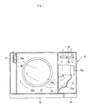
- a microwave oven comprises a body 10, housing a cooking chamber 12 and a electrical component compartment 11 partitioned from the cooking chamber 12, a door 13 connected to the body 10 by a hinge (not shown) to provide access to the cooking chamber 12, a control panel 14 installed on the front of the body 10 and provided with a plurality of functional buttons thereon (not shown), and a humidity sensor 17 which senses humidity of the cooking chamber 12.
- a turntable 12a is installed at the bottom of the cooking chamber 12 and a motor (not shown) is installed under the turntable 12 to rotate it.
- An inlet 15a providing an air flow path from the electrical component compartment 11 to the cooking chamber 12, is formed towards the front of one sidewall 15 of the cooking chamber 12.
- An outlet 16a is formed towards the back of the opposite sidewall 16 of the cooking chamber 12 to enable air in the cooking chamber 12 to be discharged to the outside.
- the electrical component compartment 11 includes a magnetron 11a which generates microwaves, a cooling fan 11b which sucks external air to cool the electrical component compartment 11 and a guide duct 11c which guides air in the electrical component compartment 11 to the inlet 15a.
- the cooling fan 11b is disposed between the magnetron 11a and a back wall of the electrical component compartment 11.
- a plurality of suction holes 11d are formed in the back wall of the electrical component compartment 11 so that external air can be drawn into the electrical component compartment 11.
- the humidity sensor 17 is mounted on the other sidewall 16 of the cooking chamber 12 adjacent to the outlet 16a to be disposed in an air discharging path from the cooking chamber 12. Therefore, the humidity sensor 17 senses the humidity of the air being discharged from the cooking chamber 12 through the outlet 16a.
- the humidity sensor 17 is electrically connected to a control unit formed in the control panel 14, as will be described later.
- the microwave oven further comprises a control unit 30 which controls the entire operations of the microwave oven.
- the control unit 30 is connected to an input unit 14a which is arranged in the control panel 14 and receives operation commands from a user.
- the control unit 30 is connected to the humidity sensor 17 which senses humidity, a weight sensor 12c installed under the turntable 12 which senses the weight of food thereon, and a temperature sensor 18 which detects the temperature of the food or the cooking chamber 12.
- a storage unit 20 is electrically connected to the control unit 30 and stores data.
- control unit 30 is electrically connected to a magnetron driving unit 41 which drives the magnetron 11a, a fan driving unit 42 which drives the cooling fan 11b, a motor driving unit 43 which drives a motor 12b for rotating the turntable 12, and a display driving unit 44 which drives a display unit 14b arranged in the control panel 14 to display information.
- the storage unit 20 stores various factors, preset according to the kind and the amount of food, and various data generated during a cooking operation.
- the microwave oven cooks the food by radiating the microwaves, generated by the magnetron 11a into the cooking chamber 12, to cook food put on the turntable 12 by a user in dependence on instructions input using the input unit 14a of the control panel 14.
- the control unit 30 drives the magnetron 11a, the motor 12b and the cooling fan 11b to automatically cook the food based on the electrical signals (including output signals from the weight sensor 12c and the temperature sensor 18 and received from the humidity sensor 17.
- the microwave oven cooks food using the maximum output power of the magnetron for a predetermined period of time. After the predetermined period of time has elapsed, the microwave oven cooks the food with the magnetron operating at a reduced power level, until the water boils. At this time, a first cooking time T1 is set as the "elapsed time prior to boiling of the water". A second cooking time T2 is calculated based on the first cooking time T1 and a preset factor.
- the second cooking time T2 is a period of time for steam boiling the food.
- the magnetron 11a operates at a lower power required to steam boil the food for a steam boil time ⁇ T3 within the second cooking time T2. After the steam boil time ⁇ T3 has elapsed, the output power of the magnetron is increased to cook the food rapidly. When the second cooking time T2 has elapsed, the cooking is finished.
- FIGS 4 to 7 show flowcharts of the method of controlling the microwave oven to cook food according to the present invention. A method of controlling the microwave oven will now be described, with reference to Figures 1-3a.
- a user puts food on the cooking tray 12a of the cooking chamber 12. Then, the user manipulates the functional buttons of the input unit 14a on the control panel 14 to set a cooking instruction, after the door 13 has been shut, in operation 100.
- control unit 30 determines whether a current set instruction is for cooking rice in a bowl, according to information input through the input unit 14a in operation 200. Where the current set instruction is for cooking the rice in a bowl in the operation 200, the control unit 30 determines whether a cooking start instruction has been input through the input unit 14a in operation 300.
- the control unit 30 When the cooking start instruction has been input in the operation 300, the control unit 30 performs an initializing operation in operation 400. In order to perform the initializing operation, the control unit 30 controls the fan driving unit 42 to operate the cooling fan 11b for an initialization time ⁇ TR. At this point, the control unit 30 does not operate the magnetron 11a.
- the control unit 30 After the initializing operation, the control unit 30 performs a first cooking operation in operation 500. After the first cooking operation, the control unit 30 sets the second cooking time T2 based on the time T1 required to perform the first cooking operation and a factor which is preset according to the kind of food and stored in the storage unit 20. Then, the control unit 30 performs the second cooking operation for the second cooking time T2 in operation 600. After the second cooking operation is completed, the control unit 30 controls the magnetron driving unit 41 to stop the operation of the magnetron 11a, and controls the fan driving unit 42 to stop the operation of the cooling fan 11b, thus completing the cooking operation in operation 700.
- the control unit 30 determines whether a reference time has elapsed after power is supplied in operation 410. If the reference time has elapsed, the control unit 30 executes a first initializing operation to drive only the cooling fan 11b for a preset first initializing time in operation 420. However, if the reference time did not elapse in the operation 410, the control unit 30 executes a second initializing operation to perform an initializing operation for a time which is longer than the preset first initializing time in operation 430.
- the control unit 30 sets the output power of the magnetron 11a to its maximum in operation 510. Then, the control unit 30 controls the magnetron driving unit 41 to operate the magnetron 11a at its maximum output power.
- the magnetron 11a radiates the microwaves to the cooking chamber 12, and the food irradiated by the microwaves is cooked thereby. While the cooling fan 11b is being driven, external air is sucked into the electrical component compartment 11 through the suction holes 11d, cooling the magnetron 11a and a high voltage transformer (not shown), and is provided to the cooking chamber 12 through the guide duct 11c and the inlet 15a. Then, the air provided to the cooking chamber 12 is discharged to the outside through the outlet 16a together with vapour generated during the cooking operation.
- the control unit 30 determines whether the water has boiled by means of the humidity sensor 17 in operation 520. Where the water does not boil at that point, the control unit 30 determines whether an instruction set at the setting operation 100 of Figure 4 is for cooking of a soaked rice in operation 530. Where the set instruction is for cooking of the soaked rice, the control unit 30 determines whether a preset first reference time A has elapsed in operation 540. Where the preset first reference time A has elapsed in the operation 540, the control unit 30 controls the magnetron driving unit 41 to decrease the output power of the magnetron 11a so as to prevent the water from overflowing in operation 550.
- the control unit 30 determines whether a preset second reference time B has elapsed in operation 530a. Where the preset second reference time B has elapsed in the operation 530a, the control unit 30 controls the magnetron driving unit 41 to decrease the output power of the magnetron 11a so as to prevent the water from overflowing in the operation 550.
- the preset first and second reference times A and B correspond to the ⁇ T1 shown in Figure 3A.
- ⁇ T1 is the time required to operate the magnetron 11a at the maximum output power to heat the food until it boils.
- the control unit 30 determines whether the water has boiled by means of the humidity sensor 17 in operation 560. Where the water has boiled in the operation 560, the control unit 30 sets an elapsed time before the water boils as the first cooking time T1 in operation 570. The control unit 30 sets the second cooking time T2 based on the set first cooking time T1 in operation 580. That is, the control unit 30 sets the second cooking time T2 by adding the first cooking time T1 to a determined period of time or by multiplying the first cooking time T1 by the preset factor according to the kind of food being cooked.
- the control unit 30 determines whether the elapsed time before the water boils exceeds a preset reference cooking time in operation 520a. Where the elapsed time does not exceed the present reference cooking time in operation 520a, the control unit 30 sets the second cooking time T2 to a preset minimum time in operation 520b, and returns to an initial operation of the second cooking operation 600 of Figure 4. Where the elapsed time exceeds the preset reference cooking time in the operation 520a, the control unit 30 proceeds to operation 570.
- the second cooking operation 600 is an operation to steam boil the food.
- the control unit 30 controls the magnetron driving unit 41 to set a current output power of the magnetron 11a to an output power preset for steam boiling the food in operation 610.
- the control unit 30 determines whether the steam boil time ( ⁇ T3 of Figure 3) preset for steam boiling t he food has elapsed in operation 620. Where the steam boil time ( ⁇ T3) has elapsed in operation 620, the control unit 30 controls the magnetron driving unit 41 to increase the output power of the magnetron 11a so as to perform rapid cooking in operation 630, and reduce the entire cooking time of the food.
- the control unit 30 determines whether the second cooking time T2 has elapsed while cooking the food, after increasing the output power of the magnetron 11a in operation 640. A length of time, which has elapsed since the output power of the magnetron 11a was increased, is obtained by subtracting the steam boil time ⁇ T3 from the second cooking time T2.
- the present invention provides a method of controlling a microwave oven, which can prevent water from boiling off/to overflow by decreasing the output power of the microwave oven before the water boils while cooking rice in a bowl.
- the present method also performs a rapid cooking by increasing the output power of the microwave oven in response to elapse of the steam boil time. Accordingly, the overall cook time and the power consumption of the microwave oven are reduced.
- the present method allows rice, whether an amount for one person or for several people, to be evenly cooked throughout. That is, with the application of the present method, a single serving of rice in a container, submerged in water, can be steam boiled evenly as the cooking time and the output of the magnetron is controlled so as not to allow the water to boil to overflow off the container. It is understood that the present invention can be applied to cook a single or multiple servings of soup, coffee, and other food items with or without the container.
- a system which uses the present invention also includes permanent or removable storage, such as magnetic and optical discs, RAM, ROM, etc., on which the process and data structures of the present invention can be stored and distributed.
- the operations can also be distributed via, for example, downloading over a network such as the Internet.
Landscapes
- Physics & Mathematics (AREA)
- Electromagnetism (AREA)
- Electric Ovens (AREA)
- Control Of High-Frequency Heating Circuits (AREA)
Applications Claiming Priority (2)
| Application Number | Priority Date | Filing Date | Title |
|---|---|---|---|
| KR10-2002-0006696A KR100453245B1 (ko) | 2002-02-06 | 2002-02-06 | 전자레인지의 제어방법 |
| KR2002006696 | 2002-02-06 |
Publications (2)
| Publication Number | Publication Date |
|---|---|
| EP1335634A2 true EP1335634A2 (de) | 2003-08-13 |
| EP1335634A3 EP1335634A3 (de) | 2005-10-19 |
Family
ID=27607074
Family Applications (1)
| Application Number | Title | Priority Date | Filing Date |
|---|---|---|---|
| EP02255453A Withdrawn EP1335634A3 (de) | 2002-02-06 | 2002-08-05 | Mikrowellenofen |
Country Status (5)
| Country | Link |
|---|---|
| US (1) | US6878912B2 (de) |
| EP (1) | EP1335634A3 (de) |
| JP (1) | JP3977196B2 (de) |
| KR (1) | KR100453245B1 (de) |
| CN (1) | CN100412447C (de) |
Families Citing this family (10)
| Publication number | Priority date | Publication date | Assignee | Title |
|---|---|---|---|---|
| EP2902711B1 (de) | 2007-03-23 | 2017-08-16 | Electrolux Home Products Corporation N.V. | Verfahren zur Zubereitung eines Gerichts in einem Backofen |
| JP4772068B2 (ja) * | 2008-01-30 | 2011-09-14 | シャープ株式会社 | 業務用の加熱調理器 |
| JP5482496B2 (ja) * | 2010-06-21 | 2014-05-07 | パナソニック株式会社 | 高周波加熱装置 |
| CN102589018B (zh) * | 2011-11-16 | 2014-10-08 | 美的集团股份有限公司 | 一种电磁炉的溢锅检测方法 |
| US10682014B2 (en) * | 2013-07-09 | 2020-06-16 | Strix Limited | Apparatus for heating food |
| KR101622038B1 (ko) * | 2014-09-23 | 2016-05-17 | 동부대우전자 주식회사 | 전자레인지 및 그 제어방법 |
| US20160116171A1 (en) * | 2014-10-22 | 2016-04-28 | General Electric Company | Oven airflow control |
| CN107676828B (zh) * | 2017-10-20 | 2019-05-07 | 浙江绍兴苏泊尔生活电器有限公司 | 电磁加热炊具及其控制方法、控制装置 |
| CN108834246B (zh) * | 2018-04-28 | 2021-09-10 | 广东美的厨房电器制造有限公司 | 半导体微波烹饪器具、烹饪控制方法及系统 |
| CN112545296B (zh) * | 2019-09-25 | 2023-08-01 | 浙江苏泊尔家电制造有限公司 | 烹饪方法、烹饪器具及计算机存储介质 |
Family Cites Families (15)
| Publication number | Priority date | Publication date | Assignee | Title |
|---|---|---|---|---|
| JPS6026939B2 (ja) * | 1977-05-06 | 1985-06-26 | 松下電器産業株式会社 | 調理器 |
| JPS61143630A (ja) * | 1984-12-14 | 1986-07-01 | Sharp Corp | 加熱器 |
| US4864088A (en) * | 1987-07-03 | 1989-09-05 | Sanyo Electric Co., Ltd. | Electronically controlled cooking apparatus for controlling heating of food using a humidity sensor |
| US4791263A (en) * | 1987-12-28 | 1988-12-13 | Whirlpool Corporation | Microwave simmering method and apparatus |
| JPH0655115B2 (ja) * | 1989-09-22 | 1994-07-27 | 三洋電機株式会社 | 電子レンジの調理制御方法 |
| KR930006906B1 (ko) * | 1990-10-31 | 1993-07-24 | 주식회사 금성사 | 전자레인지의 밥짓기 제어방법 |
| KR930010264B1 (ko) * | 1991-04-19 | 1993-10-16 | 주식회사 금성사 | 전자레인지의 밥짓기 제어방법 |
| JPH05223256A (ja) * | 1992-02-17 | 1993-08-31 | Sharp Corp | 電子レンジの調理制御方法 |
| EP0673182B1 (de) * | 1994-03-18 | 2000-03-29 | Lg Electronics Inc. | Verfahren zur automatischen Steuerung eines Mikrowellenofens |
| KR0146126B1 (ko) * | 1994-12-16 | 1998-08-17 | 구자홍 | 전자레인지의 가열시간 제어장치 및 방법 |
| JPH08322716A (ja) * | 1995-06-05 | 1996-12-10 | Sharp Corp | 誘導加熱調理器 |
| KR0154638B1 (ko) * | 1995-09-26 | 1998-11-16 | 배순훈 | 전자렌지의 밥짓기 제어방법 |
| JP3258958B2 (ja) * | 1997-04-28 | 2002-02-18 | 三洋電機株式会社 | 電子レンジ |
| SE514526C2 (sv) * | 1999-06-24 | 2001-03-05 | Whirlpool Co | Förfarande för styrning av ett kokningsförlopp i en mikrovågsugn samt mikrovågsugn härför |
| GB2366075B (en) | 2000-08-15 | 2002-10-09 | Front Direction Ind Ltd | Cooking appliance |
-
2002
- 2002-02-06 KR KR10-2002-0006696A patent/KR100453245B1/ko not_active Expired - Fee Related
- 2002-07-08 US US10/189,588 patent/US6878912B2/en not_active Expired - Fee Related
- 2002-08-02 CN CNB021282099A patent/CN100412447C/zh not_active Expired - Fee Related
- 2002-08-05 EP EP02255453A patent/EP1335634A3/de not_active Withdrawn
- 2002-08-15 JP JP2002237139A patent/JP3977196B2/ja not_active Expired - Fee Related
Also Published As
| Publication number | Publication date |
|---|---|
| US20030146209A1 (en) | 2003-08-07 |
| KR20030066933A (ko) | 2003-08-14 |
| CN100412447C (zh) | 2008-08-20 |
| CN1436966A (zh) | 2003-08-20 |
| JP3977196B2 (ja) | 2007-09-19 |
| EP1335634A3 (de) | 2005-10-19 |
| JP2003232524A (ja) | 2003-08-22 |
| US6878912B2 (en) | 2005-04-12 |
| KR100453245B1 (ko) | 2004-10-15 |
Similar Documents
| Publication | Publication Date | Title |
|---|---|---|
| EP1603366A1 (de) | Hochfrequenzheizvorrichtung und Steuerungsverfahren derselben. | |
| KR101002541B1 (ko) | 가열조리기 | |
| EP1335635A2 (de) | Mikrowellenofen | |
| EP1514503A1 (de) | Vorrichtung und Verfahrung zum Vakuumkochen | |
| EP1335634A2 (de) | Mikrowellenofen | |
| EP1335633B1 (de) | Mikrowellenofen mit Reis Kochfunktion | |
| JP2023016049A (ja) | 加熱調理器 | |
| US6867403B2 (en) | Apparatus and method for automatic cooking | |
| US5859413A (en) | Method for controlling a microwave oven to prevent overcooking of small food portions | |
| US6806449B2 (en) | Apparatus and method of controlling a microwave oven | |
| US7267833B2 (en) | Apparatus and method of automatic cooking of buckwheat | |
| KR101365880B1 (ko) | 가열조리기기 및 그 조리방법 |
Legal Events
| Date | Code | Title | Description |
|---|---|---|---|
| PUAI | Public reference made under article 153(3) epc to a published international application that has entered the european phase |
Free format text: ORIGINAL CODE: 0009012 |
|
| AK | Designated contracting states |
Designated state(s): AT BE BG CH CY CZ DE DK EE ES FI FR GB GR IE IT LI LU MC NL PT SE SK TR |
|
| AX | Request for extension of the european patent |
Extension state: AL LT LV MK RO SI |
|
| 17P | Request for examination filed |
Effective date: 20040122 |
|
| RAP1 | Party data changed (applicant data changed or rights of an application transferred) |
Owner name: SAMSUNG ELECTRONICS CO., LTD. |
|
| PUAL | Search report despatched |
Free format text: ORIGINAL CODE: 0009013 |
|
| AK | Designated contracting states |
Kind code of ref document: A3 Designated state(s): AT BE BG CH CY CZ DE DK EE ES FI FR GB GR IE IT LI LU MC NL PT SE SK TR |
|
| AX | Request for extension of the european patent |
Extension state: AL LT LV MK RO SI |
|
| AKX | Designation fees paid |
Designated state(s): DE ES FR GB IT |
|
| GRAP | Despatch of communication of intention to grant a patent |
Free format text: ORIGINAL CODE: EPIDOSNIGR1 |
|
| RIN1 | Information on inventor provided before grant (corrected) |
Inventor name: KIM, TAE-SOO Inventor name: CHO, YOUNG-WON Inventor name: KIM, CHUL Inventor name: LEE, SUNG-HO |
|
| STAA | Information on the status of an ep patent application or granted ep patent |
Free format text: STATUS: THE APPLICATION IS DEEMED TO BE WITHDRAWN |
|
| 18D | Application deemed to be withdrawn |
Effective date: 20100918 |