EP1336367A1 - Küchenmixer mit verstärktem Quirlgehäuse - Google Patents
Küchenmixer mit verstärktem Quirlgehäuse Download PDFInfo
- Publication number
- EP1336367A1 EP1336367A1 EP03290382A EP03290382A EP1336367A1 EP 1336367 A1 EP1336367 A1 EP 1336367A1 EP 03290382 A EP03290382 A EP 03290382A EP 03290382 A EP03290382 A EP 03290382A EP 1336367 A1 EP1336367 A1 EP 1336367A1
- Authority
- EP
- European Patent Office
- Prior art keywords
- whisk
- box
- insert
- support
- face
- Prior art date
- Legal status (The legal status is an assumption and is not a legal conclusion. Google has not performed a legal analysis and makes no representation as to the accuracy of the status listed.)
- Granted
Links
Images



Classifications
-
- A—HUMAN NECESSITIES
- A47—FURNITURE; DOMESTIC ARTICLES OR APPLIANCES; COFFEE MILLS; SPICE MILLS; SUCTION CLEANERS IN GENERAL
- A47J—KITCHEN EQUIPMENT; COFFEE MILLS; SPICE MILLS; APPARATUS FOR MAKING BEVERAGES
- A47J43/00—Implements for preparing or holding food, not provided for in other groups of this subclass
- A47J43/04—Machines for domestic use not covered elsewhere, e.g. for grinding, mixing, stirring, kneading, emulsifying, whipping or beating foodstuffs, e.g. power-driven
- A47J43/07—Parts or details, e.g. mixing tools, whipping tools
- A47J43/0705—Parts or details, e.g. mixing tools, whipping tools for machines with tools driven from the upper side
-
- A—HUMAN NECESSITIES
- A47—FURNITURE; DOMESTIC ARTICLES OR APPLIANCES; COFFEE MILLS; SPICE MILLS; SUCTION CLEANERS IN GENERAL
- A47J—KITCHEN EQUIPMENT; COFFEE MILLS; SPICE MILLS; APPARATUS FOR MAKING BEVERAGES
- A47J43/00—Implements for preparing or holding food, not provided for in other groups of this subclass
- A47J43/04—Machines for domestic use not covered elsewhere, e.g. for grinding, mixing, stirring, kneading, emulsifying, whipping or beating foodstuffs, e.g. power-driven
- A47J43/07—Parts or details, e.g. mixing tools, whipping tools
- A47J43/08—Driving mechanisms
- A47J43/082—Driving mechanisms for machines with tools driven from the upper side
Definitions
- the invention generally relates to mixers plunging.
- the invention relates to a mixer diving including a whisk box, a tree drive entering the whip box through a first side of this box, at least one support whip mounted fixed in translation but free in rotation compared to the whip box, and a device drive transmitting the rotational movement of the whip support drive shaft, this device drive being housed in the whip box.
- Mixers of this type are known in the art prior. They generally include two supports for whips and two whips, and are used to beat, mix or homogenize sparse preparations, like for example egg whites or mosses.
- the training devices of the prior art have the failure to transmit the reaction forces parallel to the tree which can lead to the displacement of certain bearings for guiding the device in rotation drive.
- the object of the invention is to remedy the above-mentioned faults.
- the invention is essentially characterized in that the whisk box includes a metal reinforcement insert allowing to transmit efforts to the whip support important without deformation of the whisk box.
- the metal insert surrounds the device drive.
- the whip support can be parallel to the drive shaft and enter the whisk box through a second side of this box opposite the first face, the drive device comprising a drive pinion integral in rotation with the drive shaft and having a first toothing right, a drive pinion secured to the support whip and having a second straight toothing toothing meshing with the second toothing so that the drive shaft rotates the whip holder.
- the metal insert can bring to the minus a first guide bearing in rotation of the pinion attack.
- the whisk box may include a first half-shell carrying the first crossed face by the drive shaft, and a second half-shell complementary carrying the second side crossed by the whisk holder, the metal insert comprising a half-insert upper crossed by the drive shaft and relatively closer to the first side, and a half insert lower crossed by the whip support and relatively closer to the second side, the half-insert upper being integrated in the first half-shell whip box.
- the upper half-insert can wear at least a third guide bearing in rotation of one end of the whip holder.
- the lower half-insert can carry at least a fifth rotation guide bearing of the whip holder.
- the lower half insert can include a bottom substantially perpendicular to the whip holder, one shoulder rising from bottom towards the second face and carrying the fifth bearing guide for the whip holder, and a raised rim around the bottom towards the first face, the half insert lower resting by the free end of this rim on a rib carried by the first half-shell.
- the lower half-insert can form with the first half-shell a case for the lubricant of the drive device, this housing following the shape of the drive device.
- the lower half insert can carry stiffening ribs.
- the metal insert can be in zamak, aluminum or steel.
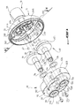
- the invention relates to a hand blender comprising in a known manner a casing (not shown), a motor electric (not shown), a whisk box 10 secured of the housing, a drive shaft 20 driven in rotation by the electric motor and entering the whip box 10 through a first face 11 of this box, at least one whip support 30 fixedly fixed in translation but free to rotate relative to the box whip 10, and a drive device 40 transmitting the rotational movement of the drive shaft 20 to whip holder 30.
- This drive device 40 is housed in the whisk box 10.
- Hand blenders generally include two whisk supports 30 parallel. Whips, no shown, are removably mounted on the whisk holders 30.
- the whip box 10 comprises a metal reinforcement insert 50 allowing transmit efforts to the whip holders 30 important without deformation of the whisk box 10.
- the metal insert 50 surrounds the device training 40.
- the whip supports 30 are parallel to the drive shaft 20 and enter the box whip 10 through a second face 12 of this box opposite the first side 11.
- These whip supports 30 each have a first part 31 cylindrical of relatively diameter smaller, extended by a second part 32 relatively larger diameter cylindrical and coaxial with the first.
- the first part 31 is located inside the whisk box 10 and the second part 32 protrudes from the second face 12.
- This second part 32 comprises a housing 34 in which a whip can be attached.
- the first face 11 is curved towards the outside of the whip box 10 and has a substantially contour oval when viewed parallel to the tree drive 20.
- This shaft 20 enters the box whip 10 by a chimney 111 located at the top of the face domed 11.
- the drive device 40 comprises a pinion attack 41, having a shape substantially cylindrical, integral in rotation with the shaft drive 20 by one end, and bringing to a opposite end a first straight toothing 411.
- This drive pinion 41 is rigidly linked to the shaft for example through a ankle 412.
- the drive device 40 also includes a drive pinion 42 secured to one of the two whip supports 30, having a disc shape, and with a second straight radial toothing 421.
- the pinion 42 is mounted coaxially on the first cylindrical part 31 of the whip support 30.
- the first teeth 411 mesh with the second toothing 421 so that the drive shaft 20 rotates the whip support 30 carrying the drive gear 42.
- the other whip support 30 is driven by two identical intermediate gears 46, each integral one of the whip supports 30, and meshing one with the other.
- These intermediate pinions 46 are mounted coaxially on the first cylindrical parts 31 of the two whip supports 30.
- the whisk box 10 includes a first half-shell 13 carrying the first face 11 crossed by the drive shaft 20, and a second half-shell complementary 14 carrying the second face 12 crossing by the whip support 30.
- the second half-shell 14 includes a bottom 141 constituting the second face 12, a rim 142 standing around the bottom 141 towards the first half-shell 13, and a protective skirt 143 with an outline closed standing up from the bottom 141 around the two whip holders 30 projecting from the second face 12.
- the second half-shell 14 is by example made of aluminum. It presents, next view the direction of the drive shaft 20, the same shape oval than the first half-shell 13.
- the bottom 141 has two holes 146 crossed by the supports whips 30.
- the first half-shell 13 forms the first face 11 and its chimney 111. It is for example made of rigid plastic. This first half-shell 13 has a free rim 132 facing the second half-shell 12 having a groove 133 forming mortise.
- the free end of the rim 142 of the second half-shell 14 has a rib 144 forming a tenon engaged in the groove 132.
- a seal 134 is arranged at the bottom of the throat 133.
- the first and second half-shells 13 and 14 are kept in the assembled state by screws 15 passing through holes 145 of the second half-shell 14 and engaged in 135 threaded holes of the first half-shell 13.
- the metal insert includes a half-insert upper 51 crossed by the drive shaft 20 and relatively closer to the first face 11, and a lower half-insert 52 through which the supports whips 30 and relatively closer to the second side 12.
- the upper half-insert 51 comprises a part substantially cylindrical coaxial with the shaft 20, flaring at one end to form a face 511 substantially perpendicular to this shaft 20.
- the central part of the first half-shell 13 of the whisk box 10 is overmolded on the upper half-insert 51, the chimney 111 surrounding the cylindrical part of the upper half-insert 51 so as to maintain the half-insert in position and stiffen the half-shell.
- the first half-shell 13 may not be molded onto the upper half-insert 51.
- One end of the drive shaft 20 is engaged in the non-flared end of the half-insert higher 51.
- the pinion gear 41 is engaged in the part cylindrical of the upper half-insert 51, and is guided in rotation by first and second guide bearings 43a and 43b secured to the upper half-insert 51 and housed in this cylindrical part.
- the upper half-insert 51 also carries third and fourth bearings 44a and 44b for guiding rotation of ends 33 of the first parts cylindrical 31 whip supports 30, these third and fourth bearings 44a and 44b being located in housings integrally with the upper half-insert 51. These housings also contain balls 47 of stop and guide in rotation of the ends 33 of whisk holders 30.
- the lower half-insert 52 carries fifths and sixth bearings 45a and 45b for guiding in rotation of the second cylindrical parts 32 of the whisk holders 30.
- the lower half-insert 52 includes a bottom 521 substantially perpendicular to the whip supports 30, two shoulders 522 rising from the bottom 521 towards the second face 12 and carrying the fifth and sixth bearings 45a and 45b for guiding the supports whips 30, and a ledge 523 rising around the bottom 521 to the first side 11.
- the shoulders 522 are substantially cylindrical and each drilled with a cylindrical orifice 526 in which is engaged the second cylindrical part 32 of one of the two whisk holders 30.
- Ribs 525 stiffen the half-insert lower 52. They extend for example between the two shoulders 522, as shown in Figure 3.
- the lower half insert 52 rests by a free end 524 of flange 523 on a rib 131 carried by the first half-shell 13.
- the upper and lower half-inserts 51 and 52 are kept in the assembled state by screws 53 passing through holes not shown carried by the half-insert lower 52 and engaged in threaded holes 512 of the upper half-insert 51.
- Wear washers 54 are interposed between the intermediate gears 46 and the fifth and sixth bearings 45a and 45b for guiding the rotation of the whips 30.
- the cylindrical holes 526 slightly flare at the free ends of the shoulders 522, thus forming spans receiving lip seals circular 55. These lip seals 55 ensure the seal between the whisk supports 30 and the shoulders 522 and serve to make up for the tolerances of manufacturing.
- O-rings 56 disposed at the outer periphery of the free ends of shoulders 522 seal between these shoulders and peripheral edges of holes 146 drilled in the bottom 141 of the second half-shell 14.
- a positioning device allows to position the two half-inserts lower and upper 52 and 51, one by compared to each other. It includes lugs carried by the lower half-insert 52, engaging in reliefs in complementary hollows in the half-insert higher 51. The shape of the reliefs allows the displacement of the pins in a given direction, so as to catch up with manufacturing tolerances.
- the metal insert 50 is preferably made of an aluminum and zinc alloy known as the name of zamak, which has the advantage of being particularly light while having good mechanical characteristics.
- the metal insert 10 can also be made in other metals, such as by example in aluminum or steel.
- the half-insert lower 52 forms with the first half-shell 13 a housing for the lubricant of the drive device 40.
- the lower half-insert 52 has a shape which closely matches the shape of the intermediate gables 46. This advantageous characteristic makes it possible to reduce the amount of lubricant required for lubrication of the drive device 40 and ensure better contact between the lubricant and the pinions.
- the immersion blender of the invention presents a whip structure box reinforced by the presence of the metal insert.
- the rotating guide bearings are all carried by the insert, which has good mechanical strength. As these are especially the parts supporting these bearings which are subjected to the constraints coming from reaction efforts of vegetables on whips, holding mechanics of the whole case is greatly improved compared to a purely housing plastic.
Landscapes
- Engineering & Computer Science (AREA)
- Mechanical Engineering (AREA)
- Food Science & Technology (AREA)
- Food-Manufacturing Devices (AREA)
- Mixers Of The Rotary Stirring Type (AREA)
- Manufacture Of Alloys Or Alloy Compounds (AREA)
Applications Claiming Priority (2)
| Application Number | Priority Date | Filing Date | Title |
|---|---|---|---|
| FR0202026A FR2836037B1 (fr) | 2002-02-18 | 2002-02-18 | Mixeur plongeant a boite fouet renforcee |
| FR0202026 | 2002-02-18 |
Publications (2)
| Publication Number | Publication Date |
|---|---|
| EP1336367A1 true EP1336367A1 (de) | 2003-08-20 |
| EP1336367B1 EP1336367B1 (de) | 2008-05-14 |
Family
ID=27620260
Family Applications (1)
| Application Number | Title | Priority Date | Filing Date |
|---|---|---|---|
| EP03290382A Expired - Lifetime EP1336367B1 (de) | 2002-02-18 | 2003-02-17 | Küchenmixer mit verstärktem Quirlgehäuse |
Country Status (5)
| Country | Link |
|---|---|
| EP (1) | EP1336367B1 (de) |
| AT (1) | ATE394981T1 (de) |
| DE (1) | DE60320877D1 (de) |
| ES (1) | ES2306844T3 (de) |
| FR (1) | FR2836037B1 (de) |
Citations (4)
| Publication number | Priority date | Publication date | Assignee | Title |
|---|---|---|---|---|
| DE1170120B (de) * | 1959-03-25 | 1964-05-14 | Expl Chimie Et Mecanique Mouli | Zerkleinerungs- und Mischgeraet |
| DE2835715A1 (de) * | 1978-08-16 | 1980-02-28 | Siemens Ag | Lageranordnung |
| DE4033020A1 (de) * | 1990-10-18 | 1992-04-23 | Krups Fa Robert | Mehrzweck-kuechenmaschine |
| EP1230883A2 (de) * | 2000-12-05 | 2002-08-14 | Sammic, S.A. | Verbesserte Küchenmaschine zum Zerkleinern und Mischen von Nahrungsmitteln |
-
2002
- 2002-02-18 FR FR0202026A patent/FR2836037B1/fr not_active Expired - Fee Related
-
2003
- 2003-02-17 DE DE60320877T patent/DE60320877D1/de not_active Expired - Lifetime
- 2003-02-17 ES ES03290382T patent/ES2306844T3/es not_active Expired - Lifetime
- 2003-02-17 AT AT03290382T patent/ATE394981T1/de active
- 2003-02-17 EP EP03290382A patent/EP1336367B1/de not_active Expired - Lifetime
Patent Citations (4)
| Publication number | Priority date | Publication date | Assignee | Title |
|---|---|---|---|---|
| DE1170120B (de) * | 1959-03-25 | 1964-05-14 | Expl Chimie Et Mecanique Mouli | Zerkleinerungs- und Mischgeraet |
| DE2835715A1 (de) * | 1978-08-16 | 1980-02-28 | Siemens Ag | Lageranordnung |
| DE4033020A1 (de) * | 1990-10-18 | 1992-04-23 | Krups Fa Robert | Mehrzweck-kuechenmaschine |
| EP1230883A2 (de) * | 2000-12-05 | 2002-08-14 | Sammic, S.A. | Verbesserte Küchenmaschine zum Zerkleinern und Mischen von Nahrungsmitteln |
Also Published As
| Publication number | Publication date |
|---|---|
| ES2306844T3 (es) | 2008-11-16 |
| FR2836037A1 (fr) | 2003-08-22 |
| ATE394981T1 (de) | 2008-05-15 |
| DE60320877D1 (de) | 2008-06-26 |
| FR2836037B1 (fr) | 2005-01-14 |
| EP1336367B1 (de) | 2008-05-14 |
Similar Documents
| Publication | Publication Date | Title |
|---|---|---|
| EP1023936B1 (de) | Rührwerk mit magnetischem Antrieb und Verfahren zur Drehmomenteinstellung für die Kraftübertragung eines derartigen Rührwerks | |
| EP0792779B1 (de) | Motorgetriebe zum Antrieb des Armes eines Kraftfahrzeugscheibenwischers | |
| EP0329578B1 (de) | Toilettensitz | |
| EP1464869A1 (de) | Flexible Verbindung zwischen dem Planetenträger und der festen Auflage eines Untersetzungsgetriebes | |
| FR2531763A1 (fr) | Appareil electrique rotatif de nettoyage | |
| EP0863331B1 (de) | Planetenuntersetzungsgetriebe mit entgegengesetzten Schrägverzahnungen | |
| FR2911361A1 (fr) | Actionneur electrique d'une portiere pivotante d'une automobile. | |
| EP1336367A1 (de) | Küchenmixer mit verstärktem Quirlgehäuse | |
| FR2812471A1 (fr) | Ensemble motoreducteur a porte-balais et joints integres | |
| FR2920406A3 (fr) | Appareil de propulsion actionne manuellement | |
| EP0686536A1 (de) | Getriebemotor mit einem Hohlen, mit einem Verschlussdeckel versehenen Gehäuse, insbesondere Scheibenwischer-Getriebemotor | |
| FR2675210A1 (fr) | Dispositif pour demarrer un moteur a combustion interne et pour fournir de l'energie electrique pendant le fonctionnement de ce moteur. | |
| EP0686537A1 (de) | Getriebemotor mit einem Hohlen, mit einem Verschlussdeckel versehenen Gehäuse, insbesondere Scheibenwischer-Getriebemotor | |
| EP0732518A2 (de) | Homokinetisches Gelenk mit Kugelgelenk | |
| EP1227747A1 (de) | Schüssel für küchenmaschine mit einer abgedichteten antriebswelle | |
| EP1850952A1 (de) | Mischer mit mischwerkzeugen, die durch die drehung des behälters angetrieben werden | |
| EP0737507B1 (de) | Mischer mit rotierendem Behälter | |
| EP1738094B1 (de) | In einer abtastvorrichtung verwendbarer antriebsmechanismus | |
| FR2877557A1 (fr) | Couvercle de fermeture d'un recipient de travail pour un appareil electromenager de preparation culinaire | |
| EP1740849A1 (de) | Mechanismus zur umwandlung einer linearen bewegung in eine bogenförmige bewegung, der bei einer erfassungsvorrichtung zum einsatz kommen kann | |
| FR2570670A1 (fr) | Dispositif d'entrainement d'un enrouleur de voile | |
| FR2751859A1 (fr) | Support de batteur electromenager | |
| FR2593257A1 (fr) | Renvoi d'angle pour transmissions mecaniques | |
| CH714171A2 (fr) | Dispositif pour remonter et/ou immobiliser un chronomètre de marine. | |
| FR2942123A1 (fr) | Boite de vitesse pour batteur melangeur |
Legal Events
| Date | Code | Title | Description |
|---|---|---|---|
| PUAI | Public reference made under article 153(3) epc to a published international application that has entered the european phase |
Free format text: ORIGINAL CODE: 0009012 |
|
| AK | Designated contracting states |
Designated state(s): AT BE BG CH CY CZ DE DK EE ES FI FR GB GR HU IE IT LI LU MC NL PT SE SI SK TR |
|
| AX | Request for extension of the european patent |
Extension state: AL LT LV MK RO |
|
| 17P | Request for examination filed |
Effective date: 20030702 |
|
| AKX | Designation fees paid |
Designated state(s): AT BE BG CH CY CZ DE DK EE ES FI FR GB GR HU IE IT LI LU MC NL PT SE SI SK TR |
|
| GRAP | Despatch of communication of intention to grant a patent |
Free format text: ORIGINAL CODE: EPIDOSNIGR1 |
|
| GRAS | Grant fee paid |
Free format text: ORIGINAL CODE: EPIDOSNIGR3 |
|
| GRAA | (expected) grant |
Free format text: ORIGINAL CODE: 0009210 |
|
| AK | Designated contracting states |
Kind code of ref document: B1 Designated state(s): AT BE BG CH CY CZ DE DK EE ES FI FR GB GR HU IE IT LI LU MC NL PT SE SI SK TR |
|
| REG | Reference to a national code |
Ref country code: GB Ref legal event code: FG4D Free format text: NOT ENGLISH |
|
| REG | Reference to a national code |
Ref country code: CH Ref legal event code: EP |
|
| REG | Reference to a national code |
Ref country code: IE Ref legal event code: FG4D |
|
| REF | Corresponds to: |
Ref document number: 60320877 Country of ref document: DE Date of ref document: 20080626 Kind code of ref document: P |
|
| REG | Reference to a national code |
Ref country code: SE Ref legal event code: TRGR |
|
| PG25 | Lapsed in a contracting state [announced via postgrant information from national office to epo] |
Ref country code: SI Free format text: LAPSE BECAUSE OF FAILURE TO SUBMIT A TRANSLATION OF THE DESCRIPTION OR TO PAY THE FEE WITHIN THE PRESCRIBED TIME-LIMIT Effective date: 20080514 |
|
| PG25 | Lapsed in a contracting state [announced via postgrant information from national office to epo] |
Ref country code: FI Free format text: LAPSE BECAUSE OF FAILURE TO SUBMIT A TRANSLATION OF THE DESCRIPTION OR TO PAY THE FEE WITHIN THE PRESCRIBED TIME-LIMIT Effective date: 20080514 |
|
| NLV1 | Nl: lapsed or annulled due to failure to fulfill the requirements of art. 29p and 29m of the patents act | ||
| REG | Reference to a national code |
Ref country code: ES Ref legal event code: FG2A Ref document number: 2306844 Country of ref document: ES Kind code of ref document: T3 |
|
| PG25 | Lapsed in a contracting state [announced via postgrant information from national office to epo] |
Ref country code: NL Free format text: LAPSE BECAUSE OF FAILURE TO SUBMIT A TRANSLATION OF THE DESCRIPTION OR TO PAY THE FEE WITHIN THE PRESCRIBED TIME-LIMIT Effective date: 20080514 |
|
| REG | Reference to a national code |
Ref country code: IE Ref legal event code: FD4D |
|
| PG25 | Lapsed in a contracting state [announced via postgrant information from national office to epo] |
Ref country code: IE Free format text: LAPSE BECAUSE OF FAILURE TO SUBMIT A TRANSLATION OF THE DESCRIPTION OR TO PAY THE FEE WITHIN THE PRESCRIBED TIME-LIMIT Effective date: 20080514 Ref country code: PT Free format text: LAPSE BECAUSE OF FAILURE TO SUBMIT A TRANSLATION OF THE DESCRIPTION OR TO PAY THE FEE WITHIN THE PRESCRIBED TIME-LIMIT Effective date: 20081014 Ref country code: DK Free format text: LAPSE BECAUSE OF FAILURE TO SUBMIT A TRANSLATION OF THE DESCRIPTION OR TO PAY THE FEE WITHIN THE PRESCRIBED TIME-LIMIT Effective date: 20080514 |
|
| PG25 | Lapsed in a contracting state [announced via postgrant information from national office to epo] |
Ref country code: SK Free format text: LAPSE BECAUSE OF FAILURE TO SUBMIT A TRANSLATION OF THE DESCRIPTION OR TO PAY THE FEE WITHIN THE PRESCRIBED TIME-LIMIT Effective date: 20080514 |
|
| PLBE | No opposition filed within time limit |
Free format text: ORIGINAL CODE: 0009261 |
|
| STAA | Information on the status of an ep patent application or granted ep patent |
Free format text: STATUS: NO OPPOSITION FILED WITHIN TIME LIMIT |
|
| 26N | No opposition filed |
Effective date: 20090217 |
|
| PG25 | Lapsed in a contracting state [announced via postgrant information from national office to epo] |
Ref country code: BG Free format text: LAPSE BECAUSE OF FAILURE TO SUBMIT A TRANSLATION OF THE DESCRIPTION OR TO PAY THE FEE WITHIN THE PRESCRIBED TIME-LIMIT Effective date: 20080814 Ref country code: EE Free format text: LAPSE BECAUSE OF FAILURE TO SUBMIT A TRANSLATION OF THE DESCRIPTION OR TO PAY THE FEE WITHIN THE PRESCRIBED TIME-LIMIT Effective date: 20080514 |
|
| BERE | Be: lapsed |
Owner name: ROBOT COUPE SNC Effective date: 20090228 |
|
| PG25 | Lapsed in a contracting state [announced via postgrant information from national office to epo] |
Ref country code: MC Free format text: LAPSE BECAUSE OF NON-PAYMENT OF DUE FEES Effective date: 20090228 |
|
| PG25 | Lapsed in a contracting state [announced via postgrant information from national office to epo] |
Ref country code: BE Free format text: LAPSE BECAUSE OF NON-PAYMENT OF DUE FEES Effective date: 20090228 |
|
| PG25 | Lapsed in a contracting state [announced via postgrant information from national office to epo] |
Ref country code: GR Free format text: LAPSE BECAUSE OF FAILURE TO SUBMIT A TRANSLATION OF THE DESCRIPTION OR TO PAY THE FEE WITHIN THE PRESCRIBED TIME-LIMIT Effective date: 20080815 |
|
| PG25 | Lapsed in a contracting state [announced via postgrant information from national office to epo] |
Ref country code: LU Free format text: LAPSE BECAUSE OF NON-PAYMENT OF DUE FEES Effective date: 20090217 |
|
| PG25 | Lapsed in a contracting state [announced via postgrant information from national office to epo] |
Ref country code: HU Free format text: LAPSE BECAUSE OF FAILURE TO SUBMIT A TRANSLATION OF THE DESCRIPTION OR TO PAY THE FEE WITHIN THE PRESCRIBED TIME-LIMIT Effective date: 20081115 |
|
| PG25 | Lapsed in a contracting state [announced via postgrant information from national office to epo] |
Ref country code: TR Free format text: LAPSE BECAUSE OF FAILURE TO SUBMIT A TRANSLATION OF THE DESCRIPTION OR TO PAY THE FEE WITHIN THE PRESCRIBED TIME-LIMIT Effective date: 20080514 |
|
| PG25 | Lapsed in a contracting state [announced via postgrant information from national office to epo] |
Ref country code: CY Free format text: LAPSE BECAUSE OF FAILURE TO SUBMIT A TRANSLATION OF THE DESCRIPTION OR TO PAY THE FEE WITHIN THE PRESCRIBED TIME-LIMIT Effective date: 20080514 |
|
| REG | Reference to a national code |
Ref country code: FR Ref legal event code: PLFP Year of fee payment: 14 |
|
| REG | Reference to a national code |
Ref country code: FR Ref legal event code: PLFP Year of fee payment: 15 |
|
| REG | Reference to a national code |
Ref country code: FR Ref legal event code: PLFP Year of fee payment: 16 |
|
| PG25 | Lapsed in a contracting state [announced via postgrant information from national office to epo] |
Ref country code: IT Free format text: LAPSE BECAUSE OF NON-PAYMENT OF DUE FEES Effective date: 20170217 |
|
| PG25 | Lapsed in a contracting state [announced via postgrant information from national office to epo] |
Ref country code: IT Free format text: LAPSE BECAUSE OF NON-PAYMENT OF DUE FEES Effective date: 20170217 |
|
| PGRI | Patent reinstated in contracting state [announced from national office to epo] |
Ref country code: IT Effective date: 20180314 |
|
| PGFP | Annual fee paid to national office [announced via postgrant information from national office to epo] |
Ref country code: CH Payment date: 20210303 Year of fee payment: 19 Ref country code: FR Payment date: 20210128 Year of fee payment: 19 Ref country code: CZ Payment date: 20210208 Year of fee payment: 19 Ref country code: IT Payment date: 20210219 Year of fee payment: 19 |
|
| PGFP | Annual fee paid to national office [announced via postgrant information from national office to epo] |
Ref country code: DE Payment date: 20210225 Year of fee payment: 19 Ref country code: SE Payment date: 20210225 Year of fee payment: 19 Ref country code: AT Payment date: 20210203 Year of fee payment: 19 Ref country code: GB Payment date: 20210225 Year of fee payment: 19 Ref country code: ES Payment date: 20210301 Year of fee payment: 19 |
|
| REG | Reference to a national code |
Ref country code: DE Ref legal event code: R119 Ref document number: 60320877 Country of ref document: DE |
|
| REG | Reference to a national code |
Ref country code: SE Ref legal event code: EUG |
|
| REG | Reference to a national code |
Ref country code: CH Ref legal event code: PL |
|
| REG | Reference to a national code |
Ref country code: AT Ref legal event code: MM01 Ref document number: 394981 Country of ref document: AT Kind code of ref document: T Effective date: 20220217 |
|
| GBPC | Gb: european patent ceased through non-payment of renewal fee |
Effective date: 20220217 |
|
| PG25 | Lapsed in a contracting state [announced via postgrant information from national office to epo] |
Ref country code: SE Free format text: LAPSE BECAUSE OF NON-PAYMENT OF DUE FEES Effective date: 20220218 Ref country code: CZ Free format text: LAPSE BECAUSE OF NON-PAYMENT OF DUE FEES Effective date: 20220217 Ref country code: AT Free format text: LAPSE BECAUSE OF NON-PAYMENT OF DUE FEES Effective date: 20220217 |
|
| PG25 | Lapsed in a contracting state [announced via postgrant information from national office to epo] |
Ref country code: FR Free format text: LAPSE BECAUSE OF NON-PAYMENT OF DUE FEES Effective date: 20220228 |
|
| PG25 | Lapsed in a contracting state [announced via postgrant information from national office to epo] |
Ref country code: LI Free format text: LAPSE BECAUSE OF NON-PAYMENT OF DUE FEES Effective date: 20220228 Ref country code: GB Free format text: LAPSE BECAUSE OF NON-PAYMENT OF DUE FEES Effective date: 20220217 Ref country code: DE Free format text: LAPSE BECAUSE OF NON-PAYMENT OF DUE FEES Effective date: 20220901 Ref country code: CH Free format text: LAPSE BECAUSE OF NON-PAYMENT OF DUE FEES Effective date: 20220228 |
|
| REG | Reference to a national code |
Ref country code: ES Ref legal event code: FD2A Effective date: 20230330 |
|
| PG25 | Lapsed in a contracting state [announced via postgrant information from national office to epo] |
Ref country code: ES Free format text: LAPSE BECAUSE OF NON-PAYMENT OF DUE FEES Effective date: 20220218 |
|
| PG25 | Lapsed in a contracting state [announced via postgrant information from national office to epo] |
Ref country code: IT Free format text: LAPSE BECAUSE OF NON-PAYMENT OF DUE FEES Effective date: 20220217 |