EP1336687B1 - Calandre de surface et un procédé pour calandrage de surface - Google Patents
Calandre de surface et un procédé pour calandrage de surface Download PDFInfo
- Publication number
- EP1336687B1 EP1336687B1 EP03002421A EP03002421A EP1336687B1 EP 1336687 B1 EP1336687 B1 EP 1336687B1 EP 03002421 A EP03002421 A EP 03002421A EP 03002421 A EP03002421 A EP 03002421A EP 1336687 B1 EP1336687 B1 EP 1336687B1
- Authority
- EP
- European Patent Office
- Prior art keywords
- roll
- carrier
- contact
- nip
- webs
- Prior art date
- Legal status (The legal status is an assumption and is not a legal conclusion. Google has not performed a legal analysis and makes no representation as to the accuracy of the status listed.)
- Expired - Lifetime
Links
- 238000000034 method Methods 0.000 title claims abstract description 37
- 238000003490 calendering Methods 0.000 title abstract description 46
- 239000000463 material Substances 0.000 claims description 42
- 238000010030 laminating Methods 0.000 claims description 35
- 238000003475 lamination Methods 0.000 claims description 26
- 238000000576 coating method Methods 0.000 claims description 25
- 239000011248 coating agent Substances 0.000 claims description 24
- 239000012530 fluid Substances 0.000 claims description 21
- 239000012876 carrier material Substances 0.000 claims description 8
- 239000012943 hotmelt Substances 0.000 claims description 8
- 239000000853 adhesive Substances 0.000 claims description 6
- -1 fleece Substances 0.000 claims description 4
- 239000004745 nonwoven fabric Substances 0.000 claims description 3
- 238000005516 engineering process Methods 0.000 claims description 2
- 239000006260 foam Substances 0.000 claims description 2
- 238000005507 spraying Methods 0.000 claims description 2
- 238000005253 cladding Methods 0.000 claims 4
- 238000001266 bandaging Methods 0.000 claims 2
- 230000003750 conditioning effect Effects 0.000 claims 2
- 239000010408 film Substances 0.000 claims 2
- 239000002759 woven fabric Substances 0.000 claims 2
- 230000008569 process Effects 0.000 description 23
- 230000035515 penetration Effects 0.000 description 9
- 238000005496 tempering Methods 0.000 description 8
- 239000000123 paper Substances 0.000 description 6
- 239000004744 fabric Substances 0.000 description 5
- 230000000694 effects Effects 0.000 description 4
- 239000000969 carrier Substances 0.000 description 3
- 239000002131 composite material Substances 0.000 description 3
- 239000000758 substrate Substances 0.000 description 3
- 230000009471 action Effects 0.000 description 2
- 238000004873 anchoring Methods 0.000 description 2
- 238000005266 casting Methods 0.000 description 2
- 238000003754 machining Methods 0.000 description 2
- 238000004519 manufacturing process Methods 0.000 description 2
- 229910052751 metal Inorganic materials 0.000 description 2
- 239000002184 metal Substances 0.000 description 2
- 239000000203 mixture Substances 0.000 description 2
- 238000003825 pressing Methods 0.000 description 2
- 238000005096 rolling process Methods 0.000 description 2
- 239000002390 adhesive tape Substances 0.000 description 1
- 229910052782 aluminium Inorganic materials 0.000 description 1
- XAGFODPZIPBFFR-UHFFFAOYSA-N aluminium Chemical compound [Al] XAGFODPZIPBFFR-UHFFFAOYSA-N 0.000 description 1
- 238000000418 atomic force spectrum Methods 0.000 description 1
- 230000009286 beneficial effect Effects 0.000 description 1
- 238000007664 blowing Methods 0.000 description 1
- 230000008859 change Effects 0.000 description 1
- 238000003776 cleavage reaction Methods 0.000 description 1
- 239000000470 constituent Substances 0.000 description 1
- 230000001419 dependent effect Effects 0.000 description 1
- 238000005485 electric heating Methods 0.000 description 1
- 230000009969 flowable effect Effects 0.000 description 1
- 238000010438 heat treatment Methods 0.000 description 1
- 239000002655 kraft paper Substances 0.000 description 1
- 238000007639 printing Methods 0.000 description 1
- 238000003672 processing method Methods 0.000 description 1
- 230000007017 scission Effects 0.000 description 1
- 239000007921 spray Substances 0.000 description 1
- 238000003892 spreading Methods 0.000 description 1
- 230000007480 spreading Effects 0.000 description 1
- 239000000126 substance Substances 0.000 description 1
- 239000004753 textile Substances 0.000 description 1
- 229920001187 thermosetting polymer Polymers 0.000 description 1
- XLYOFNOQVPJJNP-UHFFFAOYSA-N water Chemical compound O XLYOFNOQVPJJNP-UHFFFAOYSA-N 0.000 description 1
Images



Classifications
-
- B—PERFORMING OPERATIONS; TRANSPORTING
- B32—LAYERED PRODUCTS
- B32B—LAYERED PRODUCTS, i.e. PRODUCTS BUILT-UP OF STRATA OF FLAT OR NON-FLAT, e.g. CELLULAR OR HONEYCOMB, FORM
- B32B37/00—Methods or apparatus for laminating, e.g. by curing or by ultrasonic bonding
- B32B37/14—Methods or apparatus for laminating, e.g. by curing or by ultrasonic bonding characterised by the properties of the layers
- B32B37/16—Methods or apparatus for laminating, e.g. by curing or by ultrasonic bonding characterised by the properties of the layers with all layers existing as coherent layers before laminating
- B32B37/20—Methods or apparatus for laminating, e.g. by curing or by ultrasonic bonding characterised by the properties of the layers with all layers existing as coherent layers before laminating involving the assembly of continuous webs only
-
- B—PERFORMING OPERATIONS; TRANSPORTING
- B32—LAYERED PRODUCTS
- B32B—LAYERED PRODUCTS, i.e. PRODUCTS BUILT-UP OF STRATA OF FLAT OR NON-FLAT, e.g. CELLULAR OR HONEYCOMB, FORM
- B32B37/00—Methods or apparatus for laminating, e.g. by curing or by ultrasonic bonding
- B32B37/0046—Methods or apparatus for laminating, e.g. by curing or by ultrasonic bonding characterised by constructional aspects of the apparatus
- B32B37/0053—Constructional details of laminating machines comprising rollers; Constructional features of the rollers
-
- B—PERFORMING OPERATIONS; TRANSPORTING
- B32—LAYERED PRODUCTS
- B32B—LAYERED PRODUCTS, i.e. PRODUCTS BUILT-UP OF STRATA OF FLAT OR NON-FLAT, e.g. CELLULAR OR HONEYCOMB, FORM
- B32B2309/00—Parameters for the laminating or treatment process; Apparatus details
- B32B2309/06—Angles
-
- B—PERFORMING OPERATIONS; TRANSPORTING
- B32—LAYERED PRODUCTS
- B32B—LAYERED PRODUCTS, i.e. PRODUCTS BUILT-UP OF STRATA OF FLAT OR NON-FLAT, e.g. CELLULAR OR HONEYCOMB, FORM
- B32B2309/00—Parameters for the laminating or treatment process; Apparatus details
- B32B2309/16—Tension
Definitions
- the invention encompasses a surface calender and method for laminating or laminating support materials such as, for example, fabric, fleece or films, in particular for the production of dressings which are coated with hot-melt self-adhesive compositions.
- Calendering is a pressing and rolling treatment of support materials, such as paper, rubber or films, for finishing or finishing aftertreatment of fabrics, knitted fabrics, fleece or films.
- a calender can also be used for laminating or laminating materials. Between two rolls, a web-shaped material is introduced or several materials are brought together and treated or processed between the rolls. The web-shaped materials (carrier) can also be coated with other materials.
- a distinction is made between calendering, laminating, laminating and coating of carrier materials.
- Laminating is understood to mean the bonding of two support materials under the action of low to medium pressure. There is a hang up, covering the materials.
- Lamination is understood to mean the bonding of two carrier materials under the effect of generally higher pressure.
- Coating means the application / application of fluids, pastes and / or webs to a support in the form of spreading, casting, spraying, rolling, pressing or the like.
- laminating or laminating a basically identical technique can be used, so that is spoken by the calender, laminating or laminating.
- laminating or laminating which also includes the present invention, two substrates, one or both of which may be fluid coated, are laminated.
- Calendering is usually done by line contact between the rolls.
- Known simple calendering or laminating basically consist of two rolls.
- calendering also called calendering
- the product is passed in a defined path between the calender rolls.
- the gap or force between the roller pair tempering of the rollers, preheating of the laminate components or variation of the roller drive speeds, the calendering result is individually influenced. This leads u.a. on certain thickness, density or transparency values or surface effects of the calendered product.
- Figures 1 and 2 illustrate the principle of the two-roll calender ( illustration 1 ) and the multiple calender ( Figure 2 ) as known in the art.
- illustration 1 outlines a two-roll calender, with the two supports being passed between two rolls.
- Figure 2 shows a Mehrfachwalzenkalander, wherein the carriers are carried out by guide rollers one behind the other between two rollers.
- Figures 3, 4 and 5 The coating processes conventionally used in the paper, printing and textile industries in conjunction with calenders and calendering processes are outlined in Figures 3, 4 and 5.
- the illustrated calenders and calendering processes find application in the prior art even without a preceding coating. It is essential that all known devices and methods based on the principle of "line contact”. So shows Figure 3 a lamination / lamination process via engraving, screen or smooth roll against a calender roll.
- Figure 4 shows a lamination / lamination process via a coating roll against a calender roll.
- Figure 5 shows a lamination / lamination process via a roll applicator against a calender roll.
- DE 19547164 C1 describes a calender for the treatment of a paper web.
- the calender consists of several rolls, a top roll, a plurality of intermediate rolls and an end roll, which are arranged as a roll stack.
- deflection rollers By deflection rollers, the paper web passes through the respective nip of two rolls.
- the illustrated embodiments always give a line contact as a treatment zone between the rollers.
- the surface quality of the paper web can be determined by the roughness of the paper Roll surface, the temperature, the compressive stress in the nip and the gap width vary.
- WO 01/68019 A1 discloses an assembly for making stretchable closures.
- the stretchable material web is guided around a temperature-controlled roller and laminated in the nip with a second roller. Lamination over the circumference of the temperature-controlled roll does not take place.
- GB 2006109 describes the lamination of metal, primarily aluminum, by means of a calender, wherein also here the lamination between two rolls is in line contact.
- the pamphlets DE 10005306 C1 . DE 19945780 C1 . DE 10010772 C1 . DE 19820087 A1 and DE 19631056 A1 disclose calender arrangements in which the carrier webs to be laminated or also to be coated are processed by a line contact of two calender rolls.
- the machining parameters are, inter alia, always the nip and the roller pressure within the line contact gap.
- the profile adjustment on the calendering line gap is traditionally carried out by locally changing the diameter of the metal roll or the nip pressure and / or by using so-called deflection-adjustable rolls, by means of which the nip force profile can be set in the desired manner , which in turn leads to changes in the surface properties of the calendered carrier.
- the invention comprises a calendering process for surface laminating, laminating carrier webs.
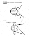
- the calender according to the invention thus consists in the simplest embodiment ( Figure 6 ) of three rolls and two carrier webs or materials to be calendered.
- the carrier webs (4, 5) are guided via the feed roller (1) through the nip (6) between the feed roller (1) and the contact roller (3).
- the carrier webs are now guided around the contact roller (3) through the nip (7) between the contact roller (3) and the discharge roller (2). They enclose the contact roller (3) in a certain circular segment (8), which is determined by the positioning of the rollers (1, 2, 3) to each other.
- the circular segment spans an angular range of the contact roller of> 180 °.
- the carrier webs thus experience in the first gap (6) and second gap (7) a Walzentinientitle and additionally on the spanned circular segment (8) (cylindrical surface segment) of the contact roller (3) a flat roller contact.
- the carrier webs are line-calendered / laminated between the rolls (1) and (3) and (2) and (3) and additionally surface calendered / laminated over the wrap-around sheet (8) of the contact roll.
- the finished product (12) can then be further processed.
- Figure 6, 7 and 8th illustrates the arrangement possibilities of the rollers (1, 2, 3) in order to produce different wrap segments, angular regions (8) of the contact roller surface looped with the carrier webs (4, 5). Circle segments with an angle range between 5 ° and 355 °, depending on the roll diameter, can be set. Preferred are contact surfaces, ie angle ranges between 90 ° and 270 °, in particular angle ranges over 180 ° and particularly preferred is an angle of 210 °.
- the gap between the feed roller (1) and the contact roller (3) and / or the gap between the Abzhouwalze (2) and the contact roller (3) can be varied as desired via the roller arrangement, so that in extreme cases no line contact in the nip (6) and / or (7).
- Figure 9 outlined this embodiment of the surface calender according to the invention by in the gap (6) no line contact and in the gap (7) line contact is made.
- the other influencing factors in the calender according to the invention are identical to those of a conventional calendering unit. That Cleavage or nip pressure setting, pre-tempering of the laminate components, roll surface etc.
- An additional decisive influencing factor in the calender according to the invention but caused by the web guide around the contact roller (3) in the laminate perpendicular to the web tension / tensile forces acting on the radial forces on the roller (3 ), which are determined in size by the web tension / tension in the laminate.
- the web tension produced in the carrier webs does not ensure, as in the conventional calenders and calendering processes, only the degree of stretching of the laminate during lamination and a wrinkle-free lamination, but also determines the surface pressure at the circle segment (8) during the lamination process.
- the tensile stress in the laminate produced at the contact roller (3) radial forces acting in the laminate perpendicular to the tensile forces and not linear but flat on the laminate. This creates a surface pressure as a function of the web tension and the cylindrical surface segment (8). Depending on the web speed, a casting time of calendering is created.
- the radial forces additionally generated by the web tension in the contact area determine the laminating, lamination process, which is only influenced by the forces (pressure, gap size) between two rolls during line contact. In line contact, the web tension can not generate radial forces.
- the penetration depth (penetration) of a fluid-coated open carrier such as paving materials, non-wovens, etc., control more secure. An undesired complete penetration of the fluid through the carrier can thus be avoided.
- the anchoring and the composite of the curing fluid with one or more carriers can be significantly influenced.
- the lamination, lamination is effected by the surface contact and thus produces a longer contact time of the materials to be treated, carrier webs.
- the tensile stress in the carrier, laminate is a factor of influence additionally generated by this technique for lamination, lamination.
- the tension creates radial forces to the contact roller which act throughout the laminating, laminating process.
- Open backings, such as paving or fabric materials, can thus be laminated more gently, laminated, and adhesive tape penetrations, such as those that can occur, in particular, during the production of patches, are avoided.
- the surface calender takes place a lower force or pressure on the wearer over a longer contact period.
- stretchable carrier materials stretching of the material by surface calendering is also possible.
- the desired stretching end state can be better stabilized, ie frozen, by the calender arrangement according to the invention.
- the surface contact also allows a better temperature control of the laminate over the rollers.
- tempering during the laminating process the desired state can be additionally stabilized before the laminate is released again.
- the tempering during lamination is thus a further additional influencing factor in comparison with the conventional line calenders and calendering methods.
- the tempering before, during and after laminating can also be carried out with common devices, IR heating, hot air blowing, various electric heating elements.
- the tempering devices for tempering can be attached to and / or in the contact roller (3).
- the calendering unit may additionally be equipped with deflecting rollers (11), as known from the known calenders of the prior art, as disclosed in US Pat Figure 10 is clarified.
- a calendering unit can consist of several surface calenders according to the invention and / or known line calenders.
- the feed (1) and / or removal rollers (2) may further be equipped with compensation cylinders, with / without piston lifting devices, so that a Spaltkraft- and / or gap size adjustment is possible, as for example DE 10010772 C1 is known.
- the possibility of variation of the influencing variables is purposefully increased by the calender according to the invention. It is possible to combine two line and one area contact calenders, one line and one area contact calender and / or only one area contact calender, thus generating individual calendering methods with specific processing parameters.
- thermosetting fluid as a laminate component, such as a hotmelt PSA
- the coating, surface laminating also on the fluid coating roll (3), as in Figure 11 is clarified.
- the carrier webs (4, 5) are guided via the feed roller (1) to the contact roller (3), here also the coating roller.
- the coating material for example hot melt fluid
- the application of the fluid can be carried out by a coating head, for example a nozzle, or else from a fluid bath, via a roller applicator and by spray technology (10).
- the coating and lamination takes place via the contact surface (8) of the contact roller (3) before the laminated product is removed via the discharge roller (2).
- the carrier is applied to the contact roller during coating. There is a coating against the contact roller (3). If the carrier is coated off roll, the coating head is adjusted below the center of the roll, so that there is a greater distance between the coating head and the contact roller and the coating material has alternative possibilities.
- the surface calender according to the invention and the calendering process ultimately also enables higher process speeds as a result of the illustrated combination possibilities and processing methods, and it is possible to greatly reduce the described advantages in terms of process energy and plant investment costs.
- the surface calender can be used for a wide variety of laminating processes / laminates.
- the laminate components can be web-shaped, network-shaped Carrier webs and / or be coated with reactive, thermal or pressure-curing fluids or coated.
- the fluids on a web-shaped structure can be applied over the entire surface or partially.
- a permanent deformation of the application by the surface calender can be achieved due to the tempering and exposure time, which is not possible with a line calendering unit.
- the carrier materials may be open carriers, fleece, fabrics, foams or so-called non-wovens.
- the materials must be tolerated by the skin, usually permeable to air and / or water vapor, as well as easy to model and to conform to.
- the surface calender according to the invention the user can set the desired machining properties specifically.
Landscapes
- Treatment Of Fiber Materials (AREA)
- Casting Or Compression Moulding Of Plastics Or The Like (AREA)
- Absorbent Articles And Supports Therefor (AREA)
- Polishing Bodies And Polishing Tools (AREA)
- Laminated Bodies (AREA)
Claims (17)
- Calandre de surface pour le traitement d'au moins deux bandes de support (4, 5), comprenant au moins un rouleau d'alimentation de bande de support (1) ; un rouleau d'évacuation de bande de support (2) et un rouleau de contact (3), les deux bandes de support (4, 5) étant guidées à travers une première fente (6) formée entre le rouleau d'alimentation de bande de support (1) et le rouleau de contact (3), autour du rouleau de contact (3) à travers une deuxième fente (7), formée entre le rouleau de contact (3) et le rouleau d'évacuation de bande de support (2), caractérisée en ce que la première fente (6) et/ou la deuxième fente (7) peuvent être modifiées par le biais de la position de rouleau du rouleau d'alimentation de bande de support (1) et/ou du rouleau d'évacuation de bande de support (2) de telle sorte qu'il se produise un contact linéaire dans la première fente (6) et/ou dans la deuxième fente (7), ou qu'il ne se produise aucun contact linéaire des bandes de support à traiter, et le rouleau d'alimentation de bande de support (1) et/ou le rouleau d'évacuation de bande de support (2) sont disposés de telle sorte qu'il en résulte un contact plan des bandes de support (4, 5) avec le rouleau de contact (3).
- Calandre de surface selon la revendication 1, caractérisée en ce que le rouleau d'alimentation de bande de support (1), le rouleau d'évacuation de bande de support (2) et le rouleau de contact (3) sont disposés de telle sorte que le segment de cercle (8) du rouleau de contact (3) couvert par les bandes de support (4, 5) couvre une plage angulaire de 5° à 355°.
- Calandre de surface selon la revendication 2, caractérisée en ce que la plage angulaire est comprise entre 90° et 270°, en particulier entre 180° et 355°, et vaut notamment 210°.
- Calandre de surface selon l'une quelconque des revendications précédentes, caractérisée en ce que le rouleau d'alimentation de bande de support (1), et/ou le rouleau d'évacuation de bande de support (2) présentent de cylindres de compensation avec ou sans dispositifs à course de piston pour l'ajustement de la force et/ou de la taille de la fente.
- Calandre de surface selon l'une quelconque des revendications précédentes, caractérisée en ce que des rouleaux de déflection (11) sont en outre disposés avant le rouleau d'alimentation de bande de support (1) et/ou après le rouleau d'évacuation de bande de support (2).
- Calandre de surface selon l'une quelconque des revendications précédentes, caractérisée en ce qu'il s'agit de bandes de support (4, 5) en forme de bande ou en forme de bande en filet et/ou de bandes de support enduites de fluides durcissant par réaction ou thermiquement ou par pression, les fluides étant appliqués complètement ou partiellement sur une structure en forme de bande.
- Calandre de surface selon l'une quelconque des revendications 1 à 5, caractérisée en ce qu'en outre le revêtement ou le laminage à plat d'une des bandes de support (4) s'effectue avec un fluide avant la première fente (6) sur le rouleau de contact (3).
- Calandre de surface selon la revendication 7, caractérisée en ce que l'application du fluide s'effectue par une tête de revêtement, une buse ou aussi à partir d'un bain de fluide, par le biais d'un dispositif d'enduction à rouleaux ou par une technique de pulvérisation (10).
- Calandre de surface selon l'une quelconque des revendications précédentes, caractérisée en ce que des dispositifs de mise en température sont montés pour la mise en température sur et/ou dans le rouleau de contact (3).
- Utilisation de la calandre de surface selon les revendications 1 à 9, pour le contrecollage et/ou le laminage de matériaux de support en forme de bande ou en forme de bande en filet.
- Utilisation de la calandre de surface selon les revendications 1 à 9, pour le contrecollage et/ou le laminage de matériaux de support ouverts, de tissus, de voiles, de feuilles, de non tissés ou de mousses.
- Utilisation de la calandre de surface selon la revendication 6 ou 7 pour le laminage de matières de bandage revêtues de compositions auto-adhésives thermofusibles.
- Utilisation de la calandre de surface selon la revendication 6 ou 7 pour le laminage de matières d'habillage revêtues de compositions auto-adhésives thermofusibles.
- Utilisation de la calandre de surface selon la revendication 13 pour la fabrication d'équipements internes de véhicules automobiles, de revêtements de sièges et/ou d'habillages de meubles.
- Procédé de calandrage de surface pour le traitement d'au moins deux bandes de support (4, 5), les deux bandes de support (4, 5) étant guidées à travers une première fente (6) formée entre le rouleau d'alimentation de bande de support (1) et le rouleau de contact (3), autour du rouleau de contact (3) à travers une deuxième fente (7), formée entre le rouleau de contact (3) et le rouleau d'évacuation de bande de support (2), caractérisé en ce que la première fente (6) et/ou la deuxième fente (7) peuvent être modifiées par le biais de la position de rouleau du rouleau d'alimentation de bande de support (1) et/ou du rouleau d'évacuation de bande de support (2) de telle sorte qu'il se produise un contact linéaire dans la première fente (6) et/ou dans la deuxième fente (7), ou qu'il ne se produise aucun contact linéaire des bandes de support à traiter, et le rouleau d'alimentation de bande de support (1) et/ou le rouleau d'évacuation de bande de support (2) sont disposés de telle sorte qu'il en résulte un contact plan des bandes de support (4, 5) avec le rouleau de contact (3), de sorte que le segment de cercle (8) du rouleau de contact (3) couvert par les bandes de support (4, 5) couvre une plage angulaire de 5° à 355°.
- Procédé de calandrage de surface selon la revendication 15, caractérisé en ce que des forces sont produites dans les bandes de support au niveau du rouleau de contact (3) par le biais de la tension de la bande ou de la tension de traction des bandes de support (4, 5, 12), afin d'influencer l'opération de contrecollage ou de laminage.
- Procédé selon la revendication 15 et la revendication 16, pour le laminage ou le contrecollage de surface de matériaux de support, de tissus, de voiles, de feuilles ou de matières de bandage et de matières d'habillage revêtues de compositions auto-adhésives thermofusibles.
Applications Claiming Priority (2)
| Application Number | Priority Date | Filing Date | Title |
|---|---|---|---|
| DE10206256 | 2002-02-13 | ||
| DE10206256A DE10206256B4 (de) | 2002-02-15 | 2002-02-15 | Flächenkalandar und Flächenkalandrierverfahren |
Publications (3)
| Publication Number | Publication Date |
|---|---|
| EP1336687A2 EP1336687A2 (fr) | 2003-08-20 |
| EP1336687A3 EP1336687A3 (fr) | 2004-06-16 |
| EP1336687B1 true EP1336687B1 (fr) | 2009-05-13 |
Family
ID=27618705
Family Applications (1)
| Application Number | Title | Priority Date | Filing Date |
|---|---|---|---|
| EP03002421A Expired - Lifetime EP1336687B1 (fr) | 2002-02-15 | 2003-02-05 | Calandre de surface et un procédé pour calandrage de surface |
Country Status (4)
| Country | Link |
|---|---|
| EP (1) | EP1336687B1 (fr) |
| AT (1) | ATE431459T1 (fr) |
| DE (2) | DE10206256B4 (fr) |
| ES (1) | ES2324211T3 (fr) |
Families Citing this family (3)
| Publication number | Priority date | Publication date | Assignee | Title |
|---|---|---|---|---|
| DE102004056154A1 (de) | 2004-11-05 | 2006-05-11 | Concert Gmbh | Walzenanordnung für die Vlies-Produktion |
| CN100545335C (zh) * | 2004-11-05 | 2009-09-30 | 康瑟特有限公司 | 用于生产纤维网的辊布置 |
| CN114770956B (zh) * | 2022-06-20 | 2022-09-30 | 苏州锐驰朗新材料有限公司 | 一种薄膜多层热压复合装置 |
Family Cites Families (13)
| Publication number | Priority date | Publication date | Assignee | Title |
|---|---|---|---|---|
| DE6602966U (de) * | 1963-10-29 | 1969-07-10 | Frans Mueller Maschinenfabrik | Vorrichtung zur veredelnden nachbehandlung von geweben und gewirken. |
| US4069081A (en) * | 1976-08-04 | 1978-01-17 | Sealtran Corporation | Method for protective film lamination with curl control |
| DE2747241C2 (de) * | 1977-10-21 | 1986-03-20 | Helmuth 2058 Lauenburg Schmoock | Verfahren zur Herstellung einer Schichtstoffkombination |
| EP0532455B1 (fr) * | 1991-09-12 | 1996-11-27 | Schaetti Ag | Installation pour calendrer et/ou laminer des matières textiles en bandes |
| DE19547164C1 (de) * | 1995-12-16 | 1997-02-06 | Voith Sulzer Finishing Gmbh | Kalander für die Behandlung einer Papierbahn und Anwendung dieses Kalanders |
| PT907509E (pt) * | 1996-05-29 | 2001-11-30 | Alusuisse Tech & Man Ag | Mecanismo de laminacao para produzir um composito laminado |
| DE19631056C2 (de) * | 1996-08-01 | 2000-08-17 | Voith Sulzer Finishing Gmbh | Kalander |
| JPH1067187A (ja) * | 1996-08-28 | 1998-03-10 | Fuji Photo Film Co Ltd | 感熱記録紙のラミネート方法及び装置 |
| DE19820087B4 (de) * | 1998-05-06 | 2005-06-23 | Eduard Küsters Maschinenfabrik GmbH & Co. KG | Kalander für die Behandlung einer Warenbahn |
| DE19945780C1 (de) * | 1999-09-24 | 2001-01-18 | Voith Paper Patent Gmbh | Kalander |
| DE10005306C1 (de) * | 2000-02-07 | 2001-06-13 | Kleinewefers Textilmaschinen G | Kalander, insbesondere für textile, Vlies- oder Kunststoff-Warenbahnen |
| DE10010772C1 (de) * | 2000-03-04 | 2001-05-10 | Voith Paper Patent Gmbh | Kalander |
| ES2307601T3 (es) * | 2000-03-14 | 2008-12-01 | Velcro Industries B.V. | Procedimiento de formacion de una fijacion extensible. |
-
2002
- 2002-02-15 DE DE10206256A patent/DE10206256B4/de not_active Expired - Fee Related
-
2003
- 2003-02-05 EP EP03002421A patent/EP1336687B1/fr not_active Expired - Lifetime
- 2003-02-05 AT AT03002421T patent/ATE431459T1/de not_active IP Right Cessation
- 2003-02-05 ES ES03002421T patent/ES2324211T3/es not_active Expired - Lifetime
- 2003-02-05 DE DE50311508T patent/DE50311508D1/de not_active Expired - Lifetime
Also Published As
| Publication number | Publication date |
|---|---|
| EP1336687A2 (fr) | 2003-08-20 |
| ATE431459T1 (de) | 2009-05-15 |
| DE10206256B4 (de) | 2006-09-21 |
| ES2324211T3 (es) | 2009-08-03 |
| DE10206256A1 (de) | 2003-09-04 |
| DE50311508D1 (de) | 2009-06-25 |
| EP1336687A3 (fr) | 2004-06-16 |
Similar Documents
| Publication | Publication Date | Title |
|---|---|---|
| DE69008375T2 (de) | Vorrichtung zur Steuerung der Querglättigkeit und Verfahren zu ihrer Anwendung. | |
| DE69919559T2 (de) | Verfahren und vorrichtung zum kalandern von papier und pappe vor und nach der beschichtung | |
| EP0451449B1 (fr) | Procédé de lissage d'une bande de papier ou carton enduite des deux côtés | |
| EP4178781A1 (fr) | Système de revêtement et procédé de revêtement | |
| EP2278067B1 (fr) | Calandre destinée au traitement d'une bande de matériau | |
| EP0453697B1 (fr) | Procédé et dispositif de fabrication d'une feuille stratifiée | |
| DE102007024581A1 (de) | Kalander und Verfahren zur Satinage von Papier- oder Kartonbahnen | |
| EP1336687B1 (fr) | Calandre de surface et un procédé pour calandrage de surface | |
| DE102016114968A1 (de) | Vorrichtung zur Behandlung von Faserbahnen | |
| DE69703610T2 (de) | Verfahren zum kalendrieren einer papierbahn und kalender zur durchführung des verfahrens | |
| EP2295632B1 (fr) | Calendre | |
| EP2275601B1 (fr) | Calandre pour lisser un papier ou une bande de carton | |
| EP1674615B1 (fr) | Procédé et arrangement pour calandrer une bande de matière fibreuse couchée sur ses deux faces | |
| AT506528B1 (de) | Verfahren und anordnung zur herstellung von mehrschichtig gestrichenem papier | |
| EP3124242A1 (fr) | Procédé et dispositif de fabrication d'une bande perméable à la vapeur d'eau | |
| EP0631012A1 (fr) | Procédé et dispositif pour le réglage de l'épaisseur, la brillance et/ou le lisse pendant le traitement de bandes fibreuses | |
| DE202016001759U1 (de) | Operationsunterlage | |
| EP1697125A1 (fr) | Procede de production de feuille de placage ignifugee et feuille de placage ignifugee correspondante | |
| DE102015113161B4 (de) | Verfahren zum Auftragen eines Mediums auf ein Substrat | |
| DE19732552A1 (de) | Verfahren zum Herstellen von Verschlußelementen bei saugfähigen Hygieneartikeln zum einmaligen Gebrauch | |
| EP2325387A2 (fr) | Calandre à plusieurs cylindres et procédé de rénovation d'une calandre à plusieurs cylindres | |
| AT410327B (de) | Verfahren und vorrichtung zur herstellung einer papierbahn | |
| DE102016201828B4 (de) | Vorrichtung und Verfahren zur Behandlung einer Faserstoffbahn | |
| EP2108737B1 (fr) | Procédé et dispositif destinés au traitement d'une bande de matière fibreuse | |
| DE10239907A1 (de) | Breitnipkalanderanordnung und Verfahren zum Satinieren einer Papier- oder Kartonbahn |
Legal Events
| Date | Code | Title | Description |
|---|---|---|---|
| PUAI | Public reference made under article 153(3) epc to a published international application that has entered the european phase |
Free format text: ORIGINAL CODE: 0009012 |
|
| AK | Designated contracting states |
Designated state(s): AT BE BG CH CY CZ DE DK EE ES FI FR GB GR HU IE IT LI LU MC NL PT SE SI SK TR |
|
| AX | Request for extension of the european patent |
Extension state: AL LT LV MK RO |
|
| PUAL | Search report despatched |
Free format text: ORIGINAL CODE: 0009013 |
|
| AK | Designated contracting states |
Kind code of ref document: A3 Designated state(s): AT BE BG CH CY CZ DE DK EE ES FI FR GB GR HU IE IT LI LU MC NL PT SE SI SK TR |
|
| AX | Request for extension of the european patent |
Extension state: AL LT LV MK RO |
|
| 17P | Request for examination filed |
Effective date: 20041216 |
|
| AKX | Designation fees paid |
Designated state(s): AT BE BG CH CY CZ DE DK EE ES FI FR GB GR HU IE IT LI LU MC NL PT SE SI SK TR |
|
| 17Q | First examination report despatched |
Effective date: 20061006 |
|
| GRAJ | Information related to disapproval of communication of intention to grant by the applicant or resumption of examination proceedings by the epo deleted |
Free format text: ORIGINAL CODE: EPIDOSDIGR1 |
|
| GRAP | Despatch of communication of intention to grant a patent |
Free format text: ORIGINAL CODE: EPIDOSNIGR1 |
|
| GRAP | Despatch of communication of intention to grant a patent |
Free format text: ORIGINAL CODE: EPIDOSNIGR1 |
|
| RIC1 | Information provided on ipc code assigned before grant |
Ipc: D21G 1/00 20060101AFI20081114BHEP Ipc: B32B 37/00 20060101ALI20081114BHEP |
|
| GRAS | Grant fee paid |
Free format text: ORIGINAL CODE: EPIDOSNIGR3 |
|
| GRAA | (expected) grant |
Free format text: ORIGINAL CODE: 0009210 |
|
| AK | Designated contracting states |
Kind code of ref document: B1 Designated state(s): AT BE BG CH CY CZ DE DK EE ES FI FR GB GR HU IE IT LI LU MC NL PT SE SI SK TR |
|
| REG | Reference to a national code |
Ref country code: GB Ref legal event code: FG4D Free format text: NOT ENGLISH |
|
| REG | Reference to a national code |
Ref country code: CH Ref legal event code: EP |
|
| REG | Reference to a national code |
Ref country code: IE Ref legal event code: FG4D |
|
| REF | Corresponds to: |
Ref document number: 50311508 Country of ref document: DE Date of ref document: 20090625 Kind code of ref document: P |
|
| REG | Reference to a national code |
Ref country code: ES Ref legal event code: FG2A Ref document number: 2324211 Country of ref document: ES Kind code of ref document: T3 |
|
| PG25 | Lapsed in a contracting state [announced via postgrant information from national office to epo] |
Ref country code: PT Free format text: LAPSE BECAUSE OF FAILURE TO SUBMIT A TRANSLATION OF THE DESCRIPTION OR TO PAY THE FEE WITHIN THE PRESCRIBED TIME-LIMIT Effective date: 20090913 Ref country code: FI Free format text: LAPSE BECAUSE OF FAILURE TO SUBMIT A TRANSLATION OF THE DESCRIPTION OR TO PAY THE FEE WITHIN THE PRESCRIBED TIME-LIMIT Effective date: 20090513 |
|
| NLV1 | Nl: lapsed or annulled due to failure to fulfill the requirements of art. 29p and 29m of the patents act | ||
| PG25 | Lapsed in a contracting state [announced via postgrant information from national office to epo] |
Ref country code: SI Free format text: LAPSE BECAUSE OF FAILURE TO SUBMIT A TRANSLATION OF THE DESCRIPTION OR TO PAY THE FEE WITHIN THE PRESCRIBED TIME-LIMIT Effective date: 20090513 Ref country code: SE Free format text: LAPSE BECAUSE OF FAILURE TO SUBMIT A TRANSLATION OF THE DESCRIPTION OR TO PAY THE FEE WITHIN THE PRESCRIBED TIME-LIMIT Effective date: 20090813 Ref country code: NL Free format text: LAPSE BECAUSE OF FAILURE TO SUBMIT A TRANSLATION OF THE DESCRIPTION OR TO PAY THE FEE WITHIN THE PRESCRIBED TIME-LIMIT Effective date: 20090513 |
|
| REG | Reference to a national code |
Ref country code: IE Ref legal event code: FD4D |
|
| PG25 | Lapsed in a contracting state [announced via postgrant information from national office to epo] |
Ref country code: EE Free format text: LAPSE BECAUSE OF FAILURE TO SUBMIT A TRANSLATION OF THE DESCRIPTION OR TO PAY THE FEE WITHIN THE PRESCRIBED TIME-LIMIT Effective date: 20090513 Ref country code: DK Free format text: LAPSE BECAUSE OF FAILURE TO SUBMIT A TRANSLATION OF THE DESCRIPTION OR TO PAY THE FEE WITHIN THE PRESCRIBED TIME-LIMIT Effective date: 20090513 Ref country code: IE Free format text: LAPSE BECAUSE OF FAILURE TO SUBMIT A TRANSLATION OF THE DESCRIPTION OR TO PAY THE FEE WITHIN THE PRESCRIBED TIME-LIMIT Effective date: 20090513 Ref country code: CZ Free format text: LAPSE BECAUSE OF FAILURE TO SUBMIT A TRANSLATION OF THE DESCRIPTION OR TO PAY THE FEE WITHIN THE PRESCRIBED TIME-LIMIT Effective date: 20090513 |
|
| PG25 | Lapsed in a contracting state [announced via postgrant information from national office to epo] |
Ref country code: SK Free format text: LAPSE BECAUSE OF FAILURE TO SUBMIT A TRANSLATION OF THE DESCRIPTION OR TO PAY THE FEE WITHIN THE PRESCRIBED TIME-LIMIT Effective date: 20090513 |
|
| PLBE | No opposition filed within time limit |
Free format text: ORIGINAL CODE: 0009261 |
|
| STAA | Information on the status of an ep patent application or granted ep patent |
Free format text: STATUS: NO OPPOSITION FILED WITHIN TIME LIMIT |
|
| PG25 | Lapsed in a contracting state [announced via postgrant information from national office to epo] |
Ref country code: BG Free format text: LAPSE BECAUSE OF FAILURE TO SUBMIT A TRANSLATION OF THE DESCRIPTION OR TO PAY THE FEE WITHIN THE PRESCRIBED TIME-LIMIT Effective date: 20090813 |
|
| 26N | No opposition filed |
Effective date: 20100216 |
|
| BERE | Be: lapsed |
Owner name: BEIERSDORF A.G. Effective date: 20100228 |
|
| REG | Reference to a national code |
Ref country code: CH Ref legal event code: PL |
|
| GBPC | Gb: european patent ceased through non-payment of renewal fee |
Effective date: 20100205 |
|
| PG25 | Lapsed in a contracting state [announced via postgrant information from national office to epo] |
Ref country code: MC Free format text: LAPSE BECAUSE OF NON-PAYMENT OF DUE FEES Effective date: 20100301 Ref country code: LI Free format text: LAPSE BECAUSE OF NON-PAYMENT OF DUE FEES Effective date: 20100228 Ref country code: CH Free format text: LAPSE BECAUSE OF NON-PAYMENT OF DUE FEES Effective date: 20100228 Ref country code: GR Free format text: LAPSE BECAUSE OF FAILURE TO SUBMIT A TRANSLATION OF THE DESCRIPTION OR TO PAY THE FEE WITHIN THE PRESCRIBED TIME-LIMIT Effective date: 20090814 |
|
| REG | Reference to a national code |
Ref country code: FR Ref legal event code: ST Effective date: 20101029 |
|
| PG25 | Lapsed in a contracting state [announced via postgrant information from national office to epo] |
Ref country code: FR Free format text: LAPSE BECAUSE OF NON-PAYMENT OF DUE FEES Effective date: 20100301 |
|
| PG25 | Lapsed in a contracting state [announced via postgrant information from national office to epo] |
Ref country code: BE Free format text: LAPSE BECAUSE OF NON-PAYMENT OF DUE FEES Effective date: 20100228 |
|
| PG25 | Lapsed in a contracting state [announced via postgrant information from national office to epo] |
Ref country code: GB Free format text: LAPSE BECAUSE OF NON-PAYMENT OF DUE FEES Effective date: 20100205 Ref country code: IT Free format text: LAPSE BECAUSE OF FAILURE TO SUBMIT A TRANSLATION OF THE DESCRIPTION OR TO PAY THE FEE WITHIN THE PRESCRIBED TIME-LIMIT Effective date: 20090513 |
|
| PG25 | Lapsed in a contracting state [announced via postgrant information from national office to epo] |
Ref country code: AT Free format text: LAPSE BECAUSE OF NON-PAYMENT OF DUE FEES Effective date: 20100205 |
|
| PG25 | Lapsed in a contracting state [announced via postgrant information from national office to epo] |
Ref country code: CY Free format text: LAPSE BECAUSE OF FAILURE TO SUBMIT A TRANSLATION OF THE DESCRIPTION OR TO PAY THE FEE WITHIN THE PRESCRIBED TIME-LIMIT Effective date: 20090513 |
|
| PG25 | Lapsed in a contracting state [announced via postgrant information from national office to epo] |
Ref country code: LU Free format text: LAPSE BECAUSE OF NON-PAYMENT OF DUE FEES Effective date: 20100205 Ref country code: HU Free format text: LAPSE BECAUSE OF FAILURE TO SUBMIT A TRANSLATION OF THE DESCRIPTION OR TO PAY THE FEE WITHIN THE PRESCRIBED TIME-LIMIT Effective date: 20091114 |
|
| PG25 | Lapsed in a contracting state [announced via postgrant information from national office to epo] |
Ref country code: TR Free format text: LAPSE BECAUSE OF FAILURE TO SUBMIT A TRANSLATION OF THE DESCRIPTION OR TO PAY THE FEE WITHIN THE PRESCRIBED TIME-LIMIT Effective date: 20090513 |
|
| PGFP | Annual fee paid to national office [announced via postgrant information from national office to epo] |
Ref country code: ES Payment date: 20160210 Year of fee payment: 14 Ref country code: DE Payment date: 20160229 Year of fee payment: 14 |
|
| REG | Reference to a national code |
Ref country code: DE Ref legal event code: R119 Ref document number: 50311508 Country of ref document: DE |
|
| PG25 | Lapsed in a contracting state [announced via postgrant information from national office to epo] |
Ref country code: DE Free format text: LAPSE BECAUSE OF NON-PAYMENT OF DUE FEES Effective date: 20170901 |
|
| REG | Reference to a national code |
Ref country code: ES Ref legal event code: FD2A Effective date: 20180706 |
|
| PG25 | Lapsed in a contracting state [announced via postgrant information from national office to epo] |
Ref country code: ES Free format text: LAPSE BECAUSE OF NON-PAYMENT OF DUE FEES Effective date: 20170206 |