EP1338449A1 - Système de climatisation de véhicule, en particulier système de climatisation à CO2 - Google Patents
Système de climatisation de véhicule, en particulier système de climatisation à CO2 Download PDFInfo
- Publication number
- EP1338449A1 EP1338449A1 EP03003752A EP03003752A EP1338449A1 EP 1338449 A1 EP1338449 A1 EP 1338449A1 EP 03003752 A EP03003752 A EP 03003752A EP 03003752 A EP03003752 A EP 03003752A EP 1338449 A1 EP1338449 A1 EP 1338449A1
- Authority
- EP
- European Patent Office
- Prior art keywords
- heat exchanger
- air conditioning
- refrigerant
- conditioning system
- valve
- Prior art date
- Legal status (The legal status is an assumption and is not a legal conclusion. Google has not performed a legal analysis and makes no representation as to the accuracy of the status listed.)
- Granted
Links
Images


Classifications
-
- B—PERFORMING OPERATIONS; TRANSPORTING
- B60—VEHICLES IN GENERAL
- B60H—ARRANGEMENTS OF HEATING, COOLING, VENTILATING OR OTHER AIR-TREATING DEVICES SPECIALLY ADAPTED FOR PASSENGER OR GOODS SPACES OF VEHICLES
- B60H1/00—Heating, cooling or ventilating devices
- B60H1/02—Heating, cooling or ventilating devices the heat being derived from the propulsion plant
- B60H1/04—Heating, cooling or ventilating devices the heat being derived from the propulsion plant from cooling liquid of the plant
- B60H1/08—Heating, cooling or ventilating devices the heat being derived from the propulsion plant from cooling liquid of the plant from other radiator than main radiator
-
- B—PERFORMING OPERATIONS; TRANSPORTING
- B60—VEHICLES IN GENERAL
- B60H—ARRANGEMENTS OF HEATING, COOLING, VENTILATING OR OTHER AIR-TREATING DEVICES SPECIALLY ADAPTED FOR PASSENGER OR GOODS SPACES OF VEHICLES
- B60H1/00—Heating, cooling or ventilating devices
- B60H1/32—Cooling devices
- B60H1/3204—Cooling devices using compression
-
- F—MECHANICAL ENGINEERING; LIGHTING; HEATING; WEAPONS; BLASTING
- F25—REFRIGERATION OR COOLING; COMBINED HEATING AND REFRIGERATION SYSTEMS; HEAT PUMP SYSTEMS; MANUFACTURE OR STORAGE OF ICE; LIQUEFACTION SOLIDIFICATION OF GASES
- F25B—REFRIGERATION MACHINES, PLANTS OR SYSTEMS; COMBINED HEATING AND REFRIGERATION SYSTEMS; HEAT PUMP SYSTEMS
- F25B2309/00—Gas cycle refrigeration machines
- F25B2309/06—Compression machines, plants or systems characterised by the refrigerant being carbon dioxide
- F25B2309/061—Compression machines, plants or systems characterised by the refrigerant being carbon dioxide with cycle highest pressure above the supercritical pressure
-
- F—MECHANICAL ENGINEERING; LIGHTING; HEATING; WEAPONS; BLASTING
- F25—REFRIGERATION OR COOLING; COMBINED HEATING AND REFRIGERATION SYSTEMS; HEAT PUMP SYSTEMS; MANUFACTURE OR STORAGE OF ICE; LIQUEFACTION SOLIDIFICATION OF GASES
- F25B—REFRIGERATION MACHINES, PLANTS OR SYSTEMS; COMBINED HEATING AND REFRIGERATION SYSTEMS; HEAT PUMP SYSTEMS
- F25B40/00—Subcoolers, desuperheaters or superheaters
-
- F—MECHANICAL ENGINEERING; LIGHTING; HEATING; WEAPONS; BLASTING
- F25—REFRIGERATION OR COOLING; COMBINED HEATING AND REFRIGERATION SYSTEMS; HEAT PUMP SYSTEMS; MANUFACTURE OR STORAGE OF ICE; LIQUEFACTION SOLIDIFICATION OF GASES
- F25B—REFRIGERATION MACHINES, PLANTS OR SYSTEMS; COMBINED HEATING AND REFRIGERATION SYSTEMS; HEAT PUMP SYSTEMS
- F25B41/00—Fluid-circulation arrangements
- F25B41/30—Expansion means; Dispositions thereof
- F25B41/39—Dispositions with two or more expansion means arranged in series, i.e. multi-stage expansion, on a refrigerant line leading to the same evaporator
-
- F—MECHANICAL ENGINEERING; LIGHTING; HEATING; WEAPONS; BLASTING
- F25—REFRIGERATION OR COOLING; COMBINED HEATING AND REFRIGERATION SYSTEMS; HEAT PUMP SYSTEMS; MANUFACTURE OR STORAGE OF ICE; LIQUEFACTION SOLIDIFICATION OF GASES
- F25B—REFRIGERATION MACHINES, PLANTS OR SYSTEMS; COMBINED HEATING AND REFRIGERATION SYSTEMS; HEAT PUMP SYSTEMS
- F25B6/00—Compression machines, plants or systems, with several condenser circuits
- F25B6/04—Compression machines, plants or systems, with several condenser circuits arranged in series
-
- F—MECHANICAL ENGINEERING; LIGHTING; HEATING; WEAPONS; BLASTING
- F25—REFRIGERATION OR COOLING; COMBINED HEATING AND REFRIGERATION SYSTEMS; HEAT PUMP SYSTEMS; MANUFACTURE OR STORAGE OF ICE; LIQUEFACTION SOLIDIFICATION OF GASES
- F25B—REFRIGERATION MACHINES, PLANTS OR SYSTEMS; COMBINED HEATING AND REFRIGERATION SYSTEMS; HEAT PUMP SYSTEMS
- F25B9/00—Compression machines, plants or systems, in which the refrigerant is air or other gas of low boiling point
- F25B9/002—Compression machines, plants or systems, in which the refrigerant is air or other gas of low boiling point characterised by the refrigerant
- F25B9/008—Compression machines, plants or systems, in which the refrigerant is air or other gas of low boiling point characterised by the refrigerant the refrigerant being carbon dioxide
Definitions
- Vehicle air conditioning systems of this type are generally known. You serve primarily for cooling the passenger compartment in summer. For the These air conditioning systems are not suitable for winter operation. There shows that modern vehicles with low-consumption engines have unsatisfactory heating output in winter. As a remedy are additional heaters, especially in these vehicles fitted as standard. In principle, air conditioning systems can also be used use as additional heating, i.e. in so-called heat pump circuit operate. Of course, this means a reversal of function conventional air conditioners, where as a refrigerant R 134a is used. Operation of conventional air conditioning systems in heat pump circuit has a relatively high circuit and Control effort. Furthermore, the heating power particularly unsatisfactory at very low outside temperatures, because the evaporation pressure depends on the temperature down to the vacuum range decreases. So that the suction density and implemented Performance correspondingly low.
- the starting point of the present invention is the conventional heating circuit of a vehicle on the one hand and the refrigerant circuit of a CO 2 air conditioning system on the other hand in accordance with FIG. 7.
- FIG. 7 shows a possible arrangement for the heating circuit of a motor vehicle and the system diagram or the refrigerant circuit of a CO 2 air conditioning system, which is designed solely for cooling operation.
- the heating circuit comprises a motor 1, a heat exchanger 2, a circulating pump 3, which is usually the main water pump of the motor 1, and a two-way valve 4.
- Essential components for the cooling circuit are an evaporator 5, a compressor 6, a refrigerant cooler 7, an inner heat exchanger 8 and an expansion valve 9.
- the heat exchanger 2 can be bridged by a by-pass line, the two-way valve 4 being arranged between this by-pass line and the heat exchanger 2, in particular the heat exchanger outlet. By appropriately switching this valve, the cooling water can either be passed through the heat exchanger 2 or past it.
- Heating operation is with the known air conditioning system according to FIG. 7 not possible.
- the object of the present invention is to create a vehicle air conditioning system, in particular a CO 2 air conditioning system, which can be easily switched from cooling operation to heating operation and can be switched in reverse.
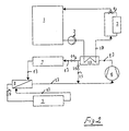
- the air conditioning system according to FIG. 1 is modified compared to the prior art according to FIG. 3 in such a way that heating operation is possible with the air conditioning system then operating as a heat pump.
- an additional heat exchanger 10 is provided, which is integrated to remove the gaseous refrigerant and to transfer the heat to a cooling water circuit.
- the cooling water circuit is marked with the reference number 17.
- the additional heat exchanger 10 there is therefore a heat exchange between the refrigerant circuit on the one hand and the engine-side cooling water circuit on the other.
- the refrigerant heated to high temperature, namely CO 2 comes from the compressor 6 connected upstream of the heat exchanger 10.
- the additional heat exchanger 10 is followed by an expansion valve 14, by means of which the refrigerant can be throttled to a lower pressure during heating operation.
- the expansion valve 14 is located in a by-pass line which branches off from the refrigerant line 13 between the additional heat exchanger 10 and the refrigerant cooler 7.
- This by-pass line is identified by reference number 15. It is connected in parallel to the coolant line mentioned, bypassing a shut-off valve 11 arranged therein.
- the shut-off valve 11 serves to shut off the free refrigerant passage between the additional heat exchanger 10 and the refrigerant cooler 7.
- the expansion valve 14 is effective, by which the pressure of the refrigerant is throttled so far that the heat exchanger serving as a refrigerant cooler in the climate case 7 absorbs ambient heat as an evaporator in heat pump operation.
- the operating mode in heating mode is as follows:
- the compressor 6 compresses the refrigerant, namely CO 2 , to a high final pressure of approximately 80-120 bar.
- the compression end temperatures are intentionally kept high, so that sufficient heat can be transferred to the engine-side heating water circuit 17 in the additional heat exchanger 10, which can then be transferred via the heat exchanger 2 is supplied to the passenger compartment.
- the refrigerant, ie CO 2 is throttled by the expansion valve 14 downstream of the additional heat exchanger 10 to a lower pressure of, for example, about 20 bar into the wet steam region and evaporates in the refrigerant cooler 7 at lower temperatures.
- the refrigerant absorbs environmental heat.
- the inner heat exchanger 8 and the evaporator 5 are flowed through without significant heat exchange.
- the valve 12 is flowed through practically without pressure loss and thus without pressure change.
- the refrigerant evaporates in the evaporator 5 and thus absorbs heat from the ambient air, which is supplied to the passenger compartment.
- the suction gas is overheated and fed to the compressor 6.
- the refrigerant is compressed to a pressure of 70-120 bar, for example, and reaches a compression end temperature of up to and above 150 ° C.
- the refrigerant is then heated in the additional heat exchanger 10 and flows through the open shut-off valve 11 into the downstream refrigerant cooler 7, energetically pre-cooled, so that only a partial cooling of the refrigerant has to take place in the refrigerant cooler 7.
- the refrigerant is then further subcooled in the inner heat exchanger and the expansion valve 9 is throttled to the evaporation pressure.
- the shut-off valve 12 in the by-pass line 18 is closed.
- Both the additional heat exchanger 10 and the refrigerant cooler 7 are available in an energetically advantageous manner for cooling the refrigerant or CO 2 gas. This makes the cooling operation more energy efficient than with a pure cooling circuit according to FIG. 3. This side effect can be used to use a cheaper refrigerant cooler or to improve the energy efficiency of the overall system.
- the heat which is transferred from the additional heat exchanger 10 to the cooling water circuit 17 can be fed directly to the engine 1 in the bypass around the heating heat exchanger 2. In the course of training, at low loads and during warm-up, this heat is used to keep the engine at an energetically favorable operating temperature and thus save fuel. If the engine is warm, the heat is dissipated via the engine cooler (not shown here).
- Such a heat exchanger downstream of the compressor and subjected to cooling water is thus also advantageous for a CO 2 air conditioning system without a heating function.
- the heat exchanger which is used as a desuperheater, no additional valves are required. This version is considered and claimed as a variant according to the invention.
- the coolant cooler 7 becomes sufficiently good on the air side flows through, so that the compression end pressure is low enough and the final compression temperature is also low. In this case is from the additional heat exchanger 10 to the then anyway hot cooling water circuit no longer transfer heat, because the temperature difference is small or even negative. The The motor is then no longer subjected to additional thermal loads. The The engine cooler therefore does not need to be larger.
- Residual heat that is not transferred to the passenger compartment in heating mode is used when the engine is cold to additionally warm up and in an energetically favorable operating point bring.
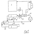
- the variant according to FIG. 2 is characterized in that the refrigerant line 13 between the additional heat exchanger 10 and refrigerant cooler 7 branches off a by-pass line 15, namely in front of one arranged in the mentioned refrigerant line 13 Shut-off valve 11.
- the by-pass line 15 is connected to the Input side of the compressor 6 immediately, i.e. under bridging of the rest of the coolant circuit fluid-connected.
- An expansion valve 16 is arranged in the by-pass line 15.
- the embodiment of Figure 2 is characterized by a hot gas by-pass circuit in heating mode through the direct connection between the refrigerant outlet of the additional heat exchanger 10 and the entrance of the Compressor 6.
- the output in the additional heat exchanger 10 Power corresponds to the power consumed by the compressor 6.
- a heat pump operation by absorbing additional environmental heat is not available.
- the expansion valve 16 must at normal cooling operation must be closed.
- the by-pass line 15 in the embodiment of Figure 2 as Execute capillary, which has a sufficient throttling effect. In this case, it would be sufficient for the valve 16 simple shut-off valve to use.
- valves can also be used in the circuits described specifically implement a dehumidification operation in which Evaporator 5 dehumidified and heating heat exchanger 2 reheated becomes.
- shut-off valves mentioned can of course also be in intermediate positions brought depending on the desired operating state.
Landscapes
- Engineering & Computer Science (AREA)
- Physics & Mathematics (AREA)
- Mechanical Engineering (AREA)
- Thermal Sciences (AREA)
- Chemical & Material Sciences (AREA)
- Combustion & Propulsion (AREA)
- General Engineering & Computer Science (AREA)
- Air-Conditioning For Vehicles (AREA)
Applications Claiming Priority (2)
| Application Number | Priority Date | Filing Date | Title |
|---|---|---|---|
| DE10207128A DE10207128A1 (de) | 2002-02-20 | 2002-02-20 | Fahrzeugklimaanlage, insbesondere CO2-Klimaanlage |
| DE10207128 | 2002-02-20 |
Publications (2)
| Publication Number | Publication Date |
|---|---|
| EP1338449A1 true EP1338449A1 (fr) | 2003-08-27 |
| EP1338449B1 EP1338449B1 (fr) | 2005-06-22 |
Family
ID=27618801
Family Applications (1)
| Application Number | Title | Priority Date | Filing Date |
|---|---|---|---|
| EP03003752A Expired - Lifetime EP1338449B1 (fr) | 2002-02-20 | 2003-02-19 | Système de climatisation de véhicule, en particulier système de climatisation à CO2 |
Country Status (3)
| Country | Link |
|---|---|
| US (1) | US6913067B2 (fr) |
| EP (1) | EP1338449B1 (fr) |
| DE (2) | DE10207128A1 (fr) |
Cited By (6)
| Publication number | Priority date | Publication date | Assignee | Title |
|---|---|---|---|---|
| DE102004024255A1 (de) * | 2004-05-15 | 2005-12-01 | Modine Manufacturing Co., Racine | Anordnung in einem Kältemittelkreislauf und Arbeitsverfahren |
| EP1813887A1 (fr) * | 2006-01-31 | 2007-08-01 | Sanyo Electric Co., Ltd. | Dispositif de climatisation |
| NL1032852C2 (nl) * | 2006-11-10 | 2008-05-14 | Antonie Bonte | Verbeterde warmtepomp. |
| WO2015091150A1 (fr) * | 2013-12-16 | 2015-06-25 | Valeo Klimasysteme Gmbh | Unité de climatisation de véhicule |
| FR3030700A1 (fr) * | 2014-12-18 | 2016-06-24 | Valeo Systemes Thermiques | Circuit de climatisation de vehicule automobile |
| WO2016185243A1 (fr) * | 2015-05-15 | 2016-11-24 | Carrier Corporation | Système d'expansion à étages |
Families Citing this family (31)
| Publication number | Priority date | Publication date | Assignee | Title |
|---|---|---|---|---|
| US7032119B2 (en) * | 2000-09-27 | 2006-04-18 | Amphus, Inc. | Dynamic power and workload management for multi-server system |
| JP3736847B2 (ja) * | 2002-12-06 | 2006-01-18 | 松下電器産業株式会社 | 空調装置及び空調方法 |
| ATE370853T1 (de) * | 2002-12-20 | 2007-09-15 | Behr Gmbh & Co Kg | Klimaanlage für ein fahrzeug und zugehöriges betriebsverfahren |
| JP2004217087A (ja) * | 2003-01-15 | 2004-08-05 | Calsonic Kansei Corp | 車両用空調装置 |
| JP2004268752A (ja) * | 2003-03-10 | 2004-09-30 | Denso Corp | 熱管理システム |
| JP2005263200A (ja) * | 2004-02-18 | 2005-09-29 | Denso Corp | 車両用空調装置 |
| DE102005001231A1 (de) * | 2005-01-11 | 2006-07-13 | Daimlerchrysler Ag | Klimaanlage für Kraftfahrzeuge |
| US7543456B2 (en) * | 2006-06-30 | 2009-06-09 | Airgenerate Llc | Heat pump liquid heater |
| US20090159259A1 (en) * | 2006-06-30 | 2009-06-25 | Sunil Kumar Sinha | Modular heat pump liquid heater system |
| US8517087B2 (en) * | 2007-02-20 | 2013-08-27 | Bergstrom, Inc. | Combined heating and air conditioning system for vehicles |
| JP4505510B2 (ja) * | 2007-02-20 | 2010-07-21 | カルソニックカンセイ株式会社 | 車両用空調システム |
| US8011598B2 (en) * | 2007-04-18 | 2011-09-06 | Delphi Technologies, Inc. | SOFC power system with A/C system and heat pump for stationary and transportation applications |
| DE102009042774A1 (de) * | 2009-09-25 | 2011-03-31 | Behr Gmbh & Co. Kg | System für ein Kraftfahrzeug zum Erwärmen und/oder Kühlen einer Batterie und eines Kraftfahrzeuginnenraumes |
| JP2011126491A (ja) * | 2009-12-21 | 2011-06-30 | Calsonic Kansei Corp | 車両用空調装置 |
| DE102009060860B4 (de) | 2009-12-30 | 2024-06-27 | Konvekta Aktiengesellschaft | Klimatisierungssystem für ein Fahrzeug sowie Verfahren zum Temperieren |
| DE102010000990B4 (de) * | 2010-01-19 | 2018-01-11 | Hanon Systems | Verfahren zum Betrieb eines Klimatisierungssystems |
| US9573437B2 (en) * | 2011-02-21 | 2017-02-21 | Hitachi, Ltd. | Vehicular air conditioning system |
| KR101416357B1 (ko) | 2012-09-07 | 2014-07-08 | 현대자동차 주식회사 | 차량용 히트펌프 시스템 및 그 제어방법 |
| DE102012215971A1 (de) * | 2012-09-10 | 2014-05-28 | Bayerische Motoren Werke Aktiengesellschaft | Verfahren zum thermischen Konditionieren eines Verbrennungsmotors und/oder eines Fahrgastraums eines Fahrzeugs sowie Fahrzeug |
| DE102012222594B4 (de) * | 2012-12-10 | 2018-05-17 | Bayerische Motoren Werke Aktiengesellschaft | Verfahren zum Betreiben eines Kältemittelkreislaufs als Wärmepumpe sowie als Wärmepumpe betreibbarer Kältemittelkreislauf |
| JP6011375B2 (ja) * | 2013-02-01 | 2016-10-19 | 株式会社デンソー | 冷凍サイクル装置 |
| KR101416416B1 (ko) * | 2013-06-03 | 2014-07-09 | 현대자동차 주식회사 | 전기 자동차용 난방 시스템 |
| US9630474B2 (en) * | 2013-10-29 | 2017-04-25 | Denso International America, Inc. | Thermostatic controlled heat pump water circuit |
| DE102014113526A1 (de) * | 2014-09-19 | 2016-03-24 | Halla Visteon Climate Control Corporation | Klimatisierungssystem für ein Kraftfahrzeug |
| FR3055249B1 (fr) * | 2016-08-30 | 2018-09-14 | Valeo Systemes Thermiques | Circuit de climatisation inversible indirect de vehicule automobile et procede de fonctionnement correspondant |
| FR3057211B1 (fr) * | 2016-10-12 | 2020-09-04 | Valeo Systemes Thermiques | Procede de regulation d'une boucle de chauffage, ventilation et/ou climatisation |
| CN108248331B (zh) * | 2016-12-29 | 2023-11-14 | 比亚迪股份有限公司 | 热泵空调系统及电动汽车 |
| KR102609407B1 (ko) * | 2017-08-21 | 2023-12-04 | 한온시스템 주식회사 | 차량용 공조장치 및 그 제어방법 |
| KR20190120936A (ko) * | 2018-04-17 | 2019-10-25 | 한온시스템 주식회사 | 차량의 열관리 시스템 |
| CN108725138B (zh) * | 2018-08-14 | 2023-09-22 | 协众国际热管理系统(江苏)股份有限公司 | 一种新能源汽车用二氧化碳热泵热管理系统及其工作方法 |
| CN116039336B (zh) * | 2023-02-03 | 2026-01-13 | 岚图汽车科技股份有限公司 | 一种换热装置、热泵系统和汽车 |
Citations (5)
| Publication number | Priority date | Publication date | Assignee | Title |
|---|---|---|---|---|
| DE19818649A1 (de) * | 1998-04-25 | 1999-10-28 | Behr Gmbh & Co | Fahrzeugklimaanlage und deren Verwendung |
| DE19850829C1 (de) * | 1998-11-04 | 2000-03-16 | Valeo Klimasysteme Gmbh | Kühl-Heiz-Kreis für ein Fahrzeug |
| JP2000211350A (ja) * | 1999-01-27 | 2000-08-02 | Japan Climate Systems Corp | 車両用空調装置 |
| DE10006513A1 (de) * | 2000-02-15 | 2001-08-16 | Behr Gmbh & Co | Klimaanlage für ein Kraftfahrzeug mit Wärmepumpen- und/oder Reheat-Betriebsart |
| DE10123830A1 (de) * | 2001-05-16 | 2002-11-28 | Bosch Gmbh Robert | Klimaanlage |
Family Cites Families (6)
| Publication number | Priority date | Publication date | Assignee | Title |
|---|---|---|---|---|
| US3446032A (en) * | 1967-03-10 | 1969-05-27 | Edward W Bottum | Heat exchanger |
| JPH06323637A (ja) * | 1993-05-18 | 1994-11-25 | Mitsubishi Heavy Ind Ltd | 冷凍サイクル |
| JPH1076841A (ja) * | 1996-09-06 | 1998-03-24 | Calsonic Corp | ヒートポンプ式自動車用空気調和装置 |
| JP3952545B2 (ja) * | 1997-07-24 | 2007-08-01 | 株式会社デンソー | 車両用空調装置 |
| DE10029934A1 (de) * | 2000-06-17 | 2002-01-03 | Behr Gmbh & Co | Klimaanlage mit Klimatisierungs- und Wärmepumpenmodus |
| US6386277B1 (en) * | 2001-04-24 | 2002-05-14 | Modine Manufacturing Company | Heat exchanger header construction |
-
2002
- 2002-02-20 DE DE10207128A patent/DE10207128A1/de not_active Withdrawn
-
2003
- 2003-02-19 EP EP03003752A patent/EP1338449B1/fr not_active Expired - Lifetime
- 2003-02-19 DE DE50300665T patent/DE50300665D1/de not_active Expired - Fee Related
- 2003-02-20 US US10/370,558 patent/US6913067B2/en not_active Expired - Lifetime
Patent Citations (5)
| Publication number | Priority date | Publication date | Assignee | Title |
|---|---|---|---|---|
| DE19818649A1 (de) * | 1998-04-25 | 1999-10-28 | Behr Gmbh & Co | Fahrzeugklimaanlage und deren Verwendung |
| DE19850829C1 (de) * | 1998-11-04 | 2000-03-16 | Valeo Klimasysteme Gmbh | Kühl-Heiz-Kreis für ein Fahrzeug |
| JP2000211350A (ja) * | 1999-01-27 | 2000-08-02 | Japan Climate Systems Corp | 車両用空調装置 |
| DE10006513A1 (de) * | 2000-02-15 | 2001-08-16 | Behr Gmbh & Co | Klimaanlage für ein Kraftfahrzeug mit Wärmepumpen- und/oder Reheat-Betriebsart |
| DE10123830A1 (de) * | 2001-05-16 | 2002-11-28 | Bosch Gmbh Robert | Klimaanlage |
Non-Patent Citations (1)
| Title |
|---|
| PATENT ABSTRACTS OF JAPAN vol. 2000, no. 11 3 January 2001 (2001-01-03) * |
Cited By (9)
| Publication number | Priority date | Publication date | Assignee | Title |
|---|---|---|---|---|
| DE102004024255A1 (de) * | 2004-05-15 | 2005-12-01 | Modine Manufacturing Co., Racine | Anordnung in einem Kältemittelkreislauf und Arbeitsverfahren |
| EP1813887A1 (fr) * | 2006-01-31 | 2007-08-01 | Sanyo Electric Co., Ltd. | Dispositif de climatisation |
| US7716934B2 (en) | 2006-01-31 | 2010-05-18 | Sanyo Electric Co., Ltd. | Air conditioning device |
| NL1032852C2 (nl) * | 2006-11-10 | 2008-05-14 | Antonie Bonte | Verbeterde warmtepomp. |
| WO2015091150A1 (fr) * | 2013-12-16 | 2015-06-25 | Valeo Klimasysteme Gmbh | Unité de climatisation de véhicule |
| FR3030700A1 (fr) * | 2014-12-18 | 2016-06-24 | Valeo Systemes Thermiques | Circuit de climatisation de vehicule automobile |
| WO2016185243A1 (fr) * | 2015-05-15 | 2016-11-24 | Carrier Corporation | Système d'expansion à étages |
| US10473369B2 (en) | 2015-05-15 | 2019-11-12 | Carrier Corporation | Staged expansion system and method |
| EP4528183A3 (fr) * | 2015-05-15 | 2025-05-14 | Carrier Corporation | Système et procédé d'expansion étagée |
Also Published As
| Publication number | Publication date |
|---|---|
| US20030177778A1 (en) | 2003-09-25 |
| US6913067B2 (en) | 2005-07-05 |
| EP1338449B1 (fr) | 2005-06-22 |
| DE50300665D1 (de) | 2005-07-28 |
| DE10207128A1 (de) | 2003-08-21 |
Similar Documents
| Publication | Publication Date | Title |
|---|---|---|
| EP1338449B1 (fr) | Système de climatisation de véhicule, en particulier système de climatisation à CO2 | |
| DE10253357B4 (de) | Kombinierte Kälteanlage/Wärmepumpe zum Einsatz in Kraftfahrzeugen zum Kühlen, Heizen und Entfeuchten des Fahrzeuginnenraumes | |
| EP1456046B1 (fr) | Fabrication et regulation d'une climatisation destinee a un vehicule | |
| EP1397265B1 (fr) | Installation de climatisation | |
| EP1164035B1 (fr) | Conditionneur d'air avec cycle de réfrigération et de pompe à chaleur | |
| EP2093083B1 (fr) | Installation de climatisation | |
| EP1467879B1 (fr) | Circuit de chauffage/refroidissement pour systeme de climatisation d'automobile, systeme de climatisation et procede pour le reguler | |
| EP1451031B1 (fr) | Installation de climatisation avec transmetteur de chaleur auxiliaire monte dans le circuit de refrigerant | |
| DE60128244T2 (de) | Verfahren und anordnung zum abtauen einer dampfverdichtungsanlage | |
| DE102006026359B4 (de) | Klimaanlage für Fahrzeuge | |
| EP1499511B1 (fr) | Installation de climatisation | |
| EP3041694B1 (fr) | Système de chauffage/ventilation de véhicules automobiles et procédé permettant de faire fonctionner un système de chauffage/ventilation de véhicules automobiles | |
| DE102017118425A1 (de) | Kreislaufsystem für ein Fahrzeug und Verfahren dazu | |
| DE102012111672A1 (de) | Kältemittelkreislauf einer Klimaanlage mit Wärmepumpen- und Nachheizfunktionalität | |
| DE112019006489T5 (de) | Fahrzeugluftkonditioniereinrichtung | |
| EP1472106B1 (fr) | Installation de climatisation ayant une fonction chauffage et son mode de fonctionnement | |
| EP1462281A2 (fr) | Appareil de climatisation avec plusieurs évaporateurs pour véhicule à moteur | |
| DE102005001231A1 (de) | Klimaanlage für Kraftfahrzeuge | |
| DE19725978A1 (de) | Kraftfahrzeugklimatisierung | |
| DE10316086B4 (de) | Fahrzeugklimaanlage, insbesondere CO2-Klimaanlage | |
| DE10239877A1 (de) | Klimaanlage für ein Fahrzeug mit einem flüssigkeitsgekühlten Antriebsaggregat, insbesondere Brennkraftmaschine | |
| DE102005005430A1 (de) | Verfahren zum Betreiben einer Klimaanlage | |
| DE602005001770T2 (de) | Klimaanlage | |
| DE3607854C2 (fr) | ||
| DE102024102082A1 (de) | Kälteanlage mit Kältemittelabschnitt zur wahlweisen Umkehr der Durchströmungsreihenfolge von Wärmeübertragern sowie Kraftfahrzeug mit einer solchen Kälteanlage |
Legal Events
| Date | Code | Title | Description |
|---|---|---|---|
| PUAI | Public reference made under article 153(3) epc to a published international application that has entered the european phase |
Free format text: ORIGINAL CODE: 0009012 |
|
| AK | Designated contracting states |
Designated state(s): AT BE BG CH CY CZ DE DK EE ES FI FR GB GR HU IE IT LI LU MC NL PT SE SI SK TR |
|
| AX | Request for extension of the european patent |
Extension state: AL LT LV MK RO |
|
| 17P | Request for examination filed |
Effective date: 20040227 |
|
| 17Q | First examination report despatched |
Effective date: 20040401 |
|
| AKX | Designation fees paid |
Designated state(s): CZ DE FR GB |
|
| RAP1 | Party data changed (applicant data changed or rights of an application transferred) |
Owner name: ZEXEL VALEO COMPRESSOR EUROPE GMBH |
|
| GRAP | Despatch of communication of intention to grant a patent |
Free format text: ORIGINAL CODE: EPIDOSNIGR1 |
|
| GRAS | Grant fee paid |
Free format text: ORIGINAL CODE: EPIDOSNIGR3 |
|
| GRAA | (expected) grant |
Free format text: ORIGINAL CODE: 0009210 |
|
| AK | Designated contracting states |
Kind code of ref document: B1 Designated state(s): CZ DE FR GB |
|
| REG | Reference to a national code |
Ref country code: GB Ref legal event code: FG4D Free format text: NOT ENGLISH |
|
| REF | Corresponds to: |
Ref document number: 50300665 Country of ref document: DE Date of ref document: 20050728 Kind code of ref document: P |
|
| GBT | Gb: translation of ep patent filed (gb section 77(6)(a)/1977) |
Effective date: 20051003 |
|
| ET | Fr: translation filed | ||
| PLBE | No opposition filed within time limit |
Free format text: ORIGINAL CODE: 0009261 |
|
| STAA | Information on the status of an ep patent application or granted ep patent |
Free format text: STATUS: NO OPPOSITION FILED WITHIN TIME LIMIT |
|
| 26N | No opposition filed |
Effective date: 20060323 |
|
| PGFP | Annual fee paid to national office [announced via postgrant information from national office to epo] |
Ref country code: CZ Payment date: 20090310 Year of fee payment: 7 |
|
| PGFP | Annual fee paid to national office [announced via postgrant information from national office to epo] |
Ref country code: GB Payment date: 20090302 Year of fee payment: 7 |
|
| PGFP | Annual fee paid to national office [announced via postgrant information from national office to epo] |
Ref country code: DE Payment date: 20090428 Year of fee payment: 7 |
|
| PGFP | Annual fee paid to national office [announced via postgrant information from national office to epo] |
Ref country code: FR Payment date: 20090227 Year of fee payment: 7 |
|
| GBPC | Gb: european patent ceased through non-payment of renewal fee |
Effective date: 20100219 |
|
| REG | Reference to a national code |
Ref country code: FR Ref legal event code: ST Effective date: 20101029 |
|
| PG25 | Lapsed in a contracting state [announced via postgrant information from national office to epo] |
Ref country code: CZ Free format text: LAPSE BECAUSE OF NON-PAYMENT OF DUE FEES Effective date: 20100219 |
|
| PG25 | Lapsed in a contracting state [announced via postgrant information from national office to epo] |
Ref country code: FR Free format text: LAPSE BECAUSE OF NON-PAYMENT OF DUE FEES Effective date: 20100301 |
|
| PG25 | Lapsed in a contracting state [announced via postgrant information from national office to epo] |
Ref country code: DE Free format text: LAPSE BECAUSE OF NON-PAYMENT OF DUE FEES Effective date: 20100901 |
|
| PG25 | Lapsed in a contracting state [announced via postgrant information from national office to epo] |
Ref country code: GB Free format text: LAPSE BECAUSE OF NON-PAYMENT OF DUE FEES Effective date: 20100219 |