EP1340618A2 - Dispositif de fixation d'une plaque d'impression flexible - Google Patents
Dispositif de fixation d'une plaque d'impression flexible Download PDFInfo
- Publication number
- EP1340618A2 EP1340618A2 EP03101548A EP03101548A EP1340618A2 EP 1340618 A2 EP1340618 A2 EP 1340618A2 EP 03101548 A EP03101548 A EP 03101548A EP 03101548 A EP03101548 A EP 03101548A EP 1340618 A2 EP1340618 A2 EP 1340618A2
- Authority
- EP
- European Patent Office
- Prior art keywords
- base body
- flap
- cylinder
- abutment
- fastening
- Prior art date
- Legal status (The legal status is an assumption and is not a legal conclusion. Google has not performed a legal analysis and makes no representation as to the accuracy of the status listed.)
- Granted
Links
- 230000001154 acute effect Effects 0.000 claims description 6
- 238000005096 rolling process Methods 0.000 claims description 4
- 239000000725 suspension Substances 0.000 claims description 3
- 230000004323 axial length Effects 0.000 description 9
- 238000004519 manufacturing process Methods 0.000 description 9
- 230000006835 compression Effects 0.000 description 3
- 238000007906 compression Methods 0.000 description 3
- 230000008878 coupling Effects 0.000 description 1
- 238000010168 coupling process Methods 0.000 description 1
- 238000005859 coupling reaction Methods 0.000 description 1
- 238000012423 maintenance Methods 0.000 description 1
Images


Classifications
-
- B—PERFORMING OPERATIONS; TRANSPORTING
- B41—PRINTING; LINING MACHINES; TYPEWRITERS; STAMPS
- B41F—PRINTING MACHINES OR PRESSES
- B41F27/00—Devices for attaching printing elements or formes to supports
- B41F27/12—Devices for attaching printing elements or formes to supports for attaching flexible printing formes
- B41F27/1218—Devices for attaching printing elements or formes to supports for attaching flexible printing formes comprising printing plate tensioning devices
- B41F27/1225—Devices for attaching printing elements or formes to supports for attaching flexible printing formes comprising printing plate tensioning devices moving in the printing plate end substantially rectilinearly
- B41F27/1243—Devices for attaching printing elements or formes to supports for attaching flexible printing formes comprising printing plate tensioning devices moving in the printing plate end substantially rectilinearly by pivotal or swivelling motion, e.g. by means of a rocking lever
-
- B—PERFORMING OPERATIONS; TRANSPORTING
- B41—PRINTING; LINING MACHINES; TYPEWRITERS; STAMPS
- B41F—PRINTING MACHINES OR PRESSES
- B41F27/00—Devices for attaching printing elements or formes to supports
- B41F27/12—Devices for attaching printing elements or formes to supports for attaching flexible printing formes
- B41F27/1262—Devices for attaching printing elements or formes to supports for attaching flexible printing formes without tensioning means
Definitions
- the invention relates to devices for fastening a flexible plate on a Cylinder of a rotary printing press according to the preamble of claim 1.
- DE 43 35 140 C1 is a device for attaching a flexible Printing plate on the forme cylinder of a rotary printing press with at least one in Axial cylinder pit known.
- a first or leading and acute angled hanging leg is on one Edge of the first pit wall of the cylinder pit of the forme cylinder hooked in.
- On the second or trailing suspension leg is along the approximately in the radial direction of the forme cylinder extending second pit wall of the cylinder pit.
- the cylinder pit receives a spindle that can be swiveled around its axis. Are on the spindle attached two leaf springs each distributed over the width of the pressure plate, which at Swiveling the spindle with the hanging legs in or out of engagement are.
- DE 196 36 412 C1 discloses a cylinder in which on a pivotable shaft Pressure cams for clamping both hanging legs of a pressure plate are arranged.
- the invention has for its object a device for attaching a to create a flexible plate on a cylinder of a rotary printing press.
- the advantages that can be achieved with the invention are in particular that a robust, simply constructed and inexpensive to manufacture device created has been.
- the device according to the invention is in only two without spindle rotation Positions adjustable.
- Another advantage of the device is that it is in their axial extent can consist of several short base bodies. Thereby it becomes possible to use the device e.g. B. piecewise for maintenance purposes from the side Remove the cylinder pit without removing the cylinder from the side frame to disassemble.
- the device also Reversal of the direction of rotation of the cylinder carrying the plates, e.g. B. at Satellite printing units, can be used. An automatic plate feed and removal using known devices is possible.
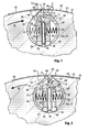
- a cylinder 01 e.g. B. a plate or blanket cylinder of a rotary printing press is for receiving flexible plates 02 with at least one in the axial direction provided 03 cylinder barrel.
- the cylinder pit 03 carries one in one Production direction A of the clockwise or clockwise direction Cylinder 01 facing front edge 04 a front or "leading" folded-in hanging leg 06 of the plate 02 with an opening angle alpha.
- the Plate 02 also has a rear or "trailing", beveled Hanging leg 07, which is the same on a second rear edge 08 Cylinder pit 03 is attached and has an approximately rectangular opening angle Beta has (Fig. 1).
- an acute opening angle Alpha is formed, e.g. B. up to 45 °.
- the second, Pit wall 13 extending approximately in the radial direction of cylinder 01 also has an acute opening angle alpha to the lateral surface 11. Both edges 04; 08 or vertices of the opening angle alpha are also through a fastening slot 09 Cut.
- the mounting slot 09 is formed in its internal width f such that next to each other at least two hanging legs 06; 07 find space in it, which in the Project cylinder pit 03.
- Printing plates also flexible carrier plates with rubber blankets arranged on them Fasten.
- the cylinder pit 03 can be approximately circular in cross section and is through the fastening slot 09 connected to the lateral surface 11.
- a base body 14 which is open in the direction of the fastening slot 09 arranged which z. B. a cross section of a longitudinally separated tube (trough-shaped) having.
- This base body 14 can be according to an embodiment shown in FIG. 1 in the axial direction from a plurality of shorter base bodies 16; 17; 18 exist - only three basic bodies are shown.
- Such a clutch can, for. B. act positively and by means of a double-sided toothing 19; 21 of the Base body 16; 17; 18 can be realized.
- the two outer teeth 19; 21 can each on the cylinder cheeks by means of an end coupling piece, not shown be locked.
- the channel-shaped base body 14 or 16 to 18 can be C-shaped, U-shaped in cross section, be oval or polygonal.
- the cross section of the cylinder pit 03 is each adapted to the cross section of the base body 14 or 16 to 18.
- the cross section shown in the drawing FIGS. 1 and 2 of the base body 14; 16 to 18 is C-shaped. An opening of the same points approximately in the direction Fastening slot 09. The following parts protrude through the opening mentioned can be brought into or out of operative connection with the hanging legs 6, 7 or 24, 26 are arranged.
- the first clamping and / or clamping elements C consist of one in the base body 14 or 16 to 18 pivotally mounted flap 27, the longitudinal axis of which axially parallel direction and its vertical axis in the radial direction to cylinder 01 extends.
- the lower side 28 of the flap 27 remote from the cylinder jacket engages in a slot 29 of the respective base body 14 or 16 to 18 and thus forms a pivot bearing.
- the flap 27 has an axial length I, which is approximately one third of the axial Total length of a base body corresponds to 16, 17 or 18 (Fig. 4).
- the Upper side 31 of the flap 27 near the cylinder jacket surface has a recess 32 which on both sides by an arm 33; 34 is limited.
- Each arm 33; 34 has an axial Length m with a clamping surface 36; 37 on.
- the axial length m corresponds approximately to one Quarter of the total axial length I of the flap 27.
- the clamping surface 36; 37 is with each a clamping surface of the abutment 38; 39 of the base body 14 or the respective Base body 16 to 18 in operative connection (Fig. 1 and 4).
- the clamping surfaces of the Abutment 38; 39 are located in the radial direction below the mounting slot 09.
- the arms 33; 34 of the flap 27 can, as in Fig. 2; 3 shown in the direction Abutment 38; 39 pointing, be bent approximately at right angles.
- the pivotable flap 27 is against the force of a spring 41 fixed to the base body, e.g. B. Compression spring, can be brought from a plate holding position into a plate removal position.
- a spring 41 fixed to the base body e.g. B. Compression spring
- the pivotable flap 27 is actuated by means of a valve which will be closer to it later descriptive inflatable air tube 42.
- a "leading" beveled hanging leg 06 of plate 02 consist of a flap 43 pivotably mounted in the base body 14 or 16 to 18, which is spaced apart by the air hose 42, runs parallel to the flap 27 (FIG. 1).
- a lower side 44 engages in a slot 46 of the respective base body 14 or 16 or 18 and forms a pivot bearing.
- the flap 43 has an axial length n. This corresponds approximately to the axial length of the Recess 32 and twice the axial length m.
- the upper side 47 of the flap 43 near the cylinder jacket is approximately at right angles in the direction bent first pit wall 12 and protrudes with its edge 49 in between the arms 33; 34 located recess 32 of the flap 27 (force application side).
- a rolling element e.g. B. held a pinch roller 48 which by means of the edge 49 Flap 43 and the force of a base-fixed spring 51, for. B. compression spring against the pressed against the first pit wall 12 "leading" hanging leg 06 becomes.
- the pivotable flap 43 is actuated by means of the between the two Flaps 27; 43 located inflatable air hose 42, which against the force of Springs 41; 51 both flaps 27; 43 pivot, d. H. can open.
- the third clamping and / or clamping elements E for one to the left in the direction of production B "leading" beveled hanging leg 24 of the plate 23 (Fig. 2 consist of a in the base body 14 or 16 to 18 pivotally mounted flap 52 with a axial length I. Parallel to the flap 52 and spaced by the air hose 42 runs a second flap 53 of equal length. Both flaps 52; 53 are each on theirs lower, d. H. Pages 54 remote from the cylinder jacket; 56 in a slot 57; 58 of each Base body 14 and 16 to 18 stored and against the force of springs 59; 61, e.g. B. Compression springs, actuable.
- An upper side 62 close to the cylinder jacket is by means of its extending in the axial direction Clamping surface or edge 63 indirectly, i. H. with the interposition of a pinch roller 64 with the second pit wall 13 or a "leading" Hanging leg 24 of the plate 23 in operative connection.
- the upper side 62 is with its edge 63 approximately at right angles, pointing in the direction of the second pit wall 13, bent.
- the pinch roller 64 is supported by an upper side surface 66 of the door 53 supported.
- the base body 14 or 16 to 18 has one in the area of the pinch roller 64 Recess 67 on.
- the clamping and / or come with each clamping of the plates 02 or 23 Clamping elements C for the "trailing" hanging leg 07 or 24 are used.
- the tensioning and / or clamping elements D for hanging legs 06 are also used.
- a plate 23 is used in the direction of rotation B of the cylinder 01, so take place the clamping and / or clamping elements D the clamping and / or clamping elements E for Commitment.
- the base body 14 or the shorter base bodies 16 to 18 are in the cylinder pit 03 preferably arranged non-rotatably.
- the inflatable air hose 42 extends in one piece over the entire length of the Cylinder pit 03.
- the air hose 42 is at one of its ends, for. B. with a valve provided and is connected via a line, not shown, to Cylinder pin and by means of a known rotary introduction with compressed air if necessary applied.
- the pressure force of each spring 51 and 59 is 61 each greater than the pressure force of the spring 41.
- the air hose 42 is initially with an air pressure of approximately three bar. This is one of the air hose 42 Exerted pressure force greater than the pressure force of the spring 41 and less than the pressure force the springs 41, 59 or 61.
- the flap 27 is pivoted and the clamping surfaces 36; 37 come out of engagement with the rear hanging leg 07 or 26.
- the "Trailing" end can be due to the internal stress of the plate 02 or 23 with its Snap the leg 07 or 26 out of the mounting slot 09 and are recorded below.
Landscapes
- Engineering & Computer Science (AREA)
- Mechanical Engineering (AREA)
- Supply, Installation And Extraction Of Printed Sheets Or Plates (AREA)
- Jigs For Machine Tools (AREA)
- Clamps And Clips (AREA)
- Dowels (AREA)
- Connection Of Plates (AREA)
- Actuator (AREA)
- Registering, Tensioning, Guiding Webs, And Rollers Therefor (AREA)
- Photoreceptors In Electrophotography (AREA)
- Insulation, Fastening Of Motor, Generator Windings (AREA)
Applications Claiming Priority (3)
| Application Number | Priority Date | Filing Date | Title |
|---|---|---|---|
| DE19924784 | 1999-05-29 | ||
| DE19924784A DE19924784C2 (de) | 1999-05-29 | 1999-05-29 | Vorrichtung zum Befestigen von biegsamen Platten auf einem Zylinder einer Rotationsdruckmaschine mit Drehrichtungsumkehr |
| EP00943646A EP1278635B1 (fr) | 1999-05-29 | 2000-05-25 | Dispositif pour fixer une plaque souple |
Related Parent Applications (1)
| Application Number | Title | Priority Date | Filing Date |
|---|---|---|---|
| EP00943646A Division EP1278635B1 (fr) | 1999-05-29 | 2000-05-25 | Dispositif pour fixer une plaque souple |
Publications (3)
| Publication Number | Publication Date |
|---|---|
| EP1340618A2 true EP1340618A2 (fr) | 2003-09-03 |
| EP1340618A3 EP1340618A3 (fr) | 2004-02-04 |
| EP1340618B1 EP1340618B1 (fr) | 2006-05-24 |
Family
ID=7909683
Family Applications (2)
| Application Number | Title | Priority Date | Filing Date |
|---|---|---|---|
| EP03101548A Expired - Lifetime EP1340618B1 (fr) | 1999-05-29 | 2000-05-25 | Dispositif de fixation d'une plaque d'impression flexible |
| EP00943646A Expired - Lifetime EP1278635B1 (fr) | 1999-05-29 | 2000-05-25 | Dispositif pour fixer une plaque souple |
Family Applications After (1)
| Application Number | Title | Priority Date | Filing Date |
|---|---|---|---|
| EP00943646A Expired - Lifetime EP1278635B1 (fr) | 1999-05-29 | 2000-05-25 | Dispositif pour fixer une plaque souple |
Country Status (6)
| Country | Link |
|---|---|
| US (2) | US6557469B1 (fr) |
| EP (2) | EP1340618B1 (fr) |
| JP (1) | JP2003522044A (fr) |
| AT (2) | ATE327100T1 (fr) |
| DE (3) | DE19924784C2 (fr) |
| WO (1) | WO2000073074A2 (fr) |
Families Citing this family (16)
| Publication number | Priority date | Publication date | Assignee | Title |
|---|---|---|---|---|
| DE10058996C1 (de) | 2000-11-28 | 2002-06-13 | Koenig & Bauer Ag | Vorrichtung zur Befestigung eines Aufzuges |
| DE10218474A1 (de) * | 2002-04-25 | 2003-11-20 | Koenig & Bauer Ag | Vorrichtungen zum Befestigen von mindestens einem Aufzug auf einem Zylinder einer Rotationsdruckmaschine und ein Druckwerk mit dieser Vorrichtung |
| DE10220546B4 (de) * | 2002-05-08 | 2004-05-27 | Koenig & Bauer Ag | Vorrichtung zum Befestigen von mindestens einem biegsamen Aufzug mit mindestens einem abgekanteten Schenkel auf einer Mantelfläche eines Zylinders einer Rotationsdruckmaschine |
| DE10220548B4 (de) | 2002-05-08 | 2004-05-27 | Koenig & Bauer Ag | Befestigung eines biegsamen Aufzugs auf einem Zylinder einer Rotationsdruckmaschine |
| DE10228971B4 (de) * | 2002-06-26 | 2009-12-31 | Koenig & Bauer Aktiengesellschaft | Biegsamer Aufzug zur Verwendung auf einem Zylinder einer Rotationsdruckmaschine |
| DE10250684B3 (de) * | 2002-10-31 | 2004-04-01 | Koenig & Bauer Ag | Verfahren zur Herstellung eines Rotationskörpers und Rotationskörper einer Druckmaschine |
| DE10360012A1 (de) * | 2003-12-19 | 2005-07-28 | Man Roland Druckmaschinen Ag | Gummituchplatte zum Aufspannen auf einen Zylinder |
| DE102004001397A1 (de) * | 2004-01-09 | 2005-08-04 | Koenig & Bauer Ag | Zylinder einer Druckmaschine mit mindestens einem Spannkanal und ein Verfahren zur Herstellung eines Zylinders |
| DE102004054997B4 (de) * | 2004-01-09 | 2008-01-17 | Koenig & Bauer Aktiengesellschaft | Zylinder einer Druckmaschine mit mindestens einem Spannkanal |
| DE102006032264A1 (de) * | 2006-07-12 | 2008-01-17 | Maschinenfabrik Wifag | Klemmvorrichtung mit kippbarem Klemmstück |
| US20080216691A1 (en) * | 2007-03-05 | 2008-09-11 | Stephens Ronald F | Printing plate lock mechanisms |
| DE102007047892B4 (de) * | 2007-11-29 | 2010-07-15 | Koenig & Bauer Aktiengesellschaft | Zylinder einer Druckmaschine mit mindestens einem unter dessen Mantelfläche in dessen Axialrichtung verlaufenden Kanal |
| DE102012207109B3 (de) | 2012-04-27 | 2013-05-02 | Koenig & Bauer Aktiengesellschaft | Verfahren zum Anordnen einer Druckform auf einen Plattenzylinder |
| DE102012207106B4 (de) | 2012-04-27 | 2015-04-02 | Koenig & Bauer Aktiengesellschaft | Plattenzylinder |
| DE102012207101B4 (de) * | 2012-04-27 | 2016-06-23 | Koenig & Bauer Ag | Plattenzylinder |
| DE102012214585B4 (de) | 2012-08-16 | 2014-09-04 | Koenig & Bauer Aktiengesellschaft | Verfahren zum registerhaltigen Anordnen jeweils zumindest einer Druckplatte auf zumindest zwei Plattenzylindern einer Druckmaschine und ein System zur Registerregelung |
Citations (2)
| Publication number | Priority date | Publication date | Assignee | Title |
|---|---|---|---|---|
| DE4335140C1 (de) | 1993-10-15 | 1995-02-02 | Roland Man Druckmasch | Vorrichtung zum Befestigen einer biegsamen Druckplatte |
| DE19636412C1 (de) | 1996-09-07 | 1998-01-08 | Koenig & Bauer Albert Ag | Zylinder |
Family Cites Families (12)
| Publication number | Priority date | Publication date | Assignee | Title |
|---|---|---|---|---|
| US2973818A (en) | 1956-07-26 | 1961-03-07 | George I N Marvin | Wheeled trailer for liquid fertilizer applying apparatus |
| US2973710A (en) * | 1958-03-14 | 1961-03-07 | Hantscho George | Printing press rollers |
| FR1499664A (fr) | 1966-11-09 | 1967-10-27 | Miehle Goss Dexter Inc | Mécanisme de blocage des clichés pour cylindre porte-plaques réversible de machine d'imprimerie |
| US3727551A (en) * | 1971-07-22 | 1973-04-17 | North American Rockwell | Reversible lockup for flexible printing plate |
| US4347788A (en) * | 1980-05-01 | 1982-09-07 | Harris Corporation | Plate lockup mechanism |
| GB8616952D0 (en) * | 1986-07-11 | 1986-08-20 | Hercules Inc | Printing plate |
| DD266233A3 (de) * | 1987-07-02 | 1989-03-29 | Polygraph Leipzig | Vorrichtung zum befestigen einer biegsamen druckplatte |
| DE3731779A1 (de) * | 1987-09-22 | 1989-03-30 | Koenig & Bauer Ag | Vorrichtung zum aufspannen von biegsamen druckplatten auf formzylinder von rotationsdruckmaschinen |
| US5010818A (en) * | 1988-02-29 | 1991-04-30 | Rockwell International Corporation | Tensionless plate lock-up |
| DE4244077C2 (de) * | 1992-12-24 | 1995-06-08 | Koenig & Bauer Ag | Vorrichtung zum Aufspannen von biegsamen Druckplatten auf einen Formzylinder einer Rotationsdruckmaschine |
| US5485784A (en) * | 1994-06-28 | 1996-01-23 | Walschlaeger, Sr.; Alan R. | Printing plate cylinder with universal lockup apparatus |
| DE10060984B4 (de) * | 2000-12-08 | 2006-10-26 | Man Roland Druckmaschinen Ag | Vorichtung zum Befestigen einer Bespannung auf einem Druckwerkzylinder |
-
1999
- 1999-05-29 DE DE19924784A patent/DE19924784C2/de not_active Expired - Fee Related
-
2000
- 2000-05-25 US US09/926,646 patent/US6557469B1/en not_active Expired - Fee Related
- 2000-05-25 DE DE50007026T patent/DE50007026D1/de not_active Expired - Fee Related
- 2000-05-25 JP JP2000621168A patent/JP2003522044A/ja active Pending
- 2000-05-25 AT AT03101548T patent/ATE327100T1/de not_active IP Right Cessation
- 2000-05-25 WO PCT/DE2000/001699 patent/WO2000073074A2/fr not_active Ceased
- 2000-05-25 EP EP03101548A patent/EP1340618B1/fr not_active Expired - Lifetime
- 2000-05-25 EP EP00943646A patent/EP1278635B1/fr not_active Expired - Lifetime
- 2000-05-25 DE DE50012834T patent/DE50012834D1/de not_active Expired - Lifetime
- 2000-05-25 AT AT00943646T patent/ATE270617T1/de not_active IP Right Cessation
-
2003
- 2003-03-26 US US10/396,497 patent/US6675708B2/en not_active Expired - Fee Related
Patent Citations (2)
| Publication number | Priority date | Publication date | Assignee | Title |
|---|---|---|---|---|
| DE4335140C1 (de) | 1993-10-15 | 1995-02-02 | Roland Man Druckmasch | Vorrichtung zum Befestigen einer biegsamen Druckplatte |
| DE19636412C1 (de) | 1996-09-07 | 1998-01-08 | Koenig & Bauer Albert Ag | Zylinder |
Also Published As
| Publication number | Publication date |
|---|---|
| EP1340618B1 (fr) | 2006-05-24 |
| US6557469B1 (en) | 2003-05-06 |
| DE19924784A1 (de) | 2000-12-07 |
| WO2000073074A3 (fr) | 2002-10-17 |
| EP1278635B1 (fr) | 2004-07-07 |
| DE50012834D1 (de) | 2006-06-29 |
| EP1278635A2 (fr) | 2003-01-29 |
| DE19924784C2 (de) | 2001-05-31 |
| EP1340618A3 (fr) | 2004-02-04 |
| ATE270617T1 (de) | 2004-07-15 |
| DE50007026D1 (de) | 2004-08-12 |
| JP2003522044A (ja) | 2003-07-22 |
| ATE327100T1 (de) | 2006-06-15 |
| WO2000073074A2 (fr) | 2000-12-07 |
| US6675708B2 (en) | 2004-01-13 |
| US20030159604A1 (en) | 2003-08-28 |
Similar Documents
| Publication | Publication Date | Title |
|---|---|---|
| EP1340617B1 (fr) | Dispositif de fixation d'une plaque d'impression flexible | |
| DE19924784C2 (de) | Vorrichtung zum Befestigen von biegsamen Platten auf einem Zylinder einer Rotationsdruckmaschine mit Drehrichtungsumkehr | |
| EP1350624B1 (fr) | Dispositif pour la fixation d'une plaque flexible | |
| DE2804556C2 (de) | Abnehmbare Kanalabdeckung von Zylinderkanälen bei Druckmaschinen | |
| EP0732203B1 (fr) | Dispositif tendeur | |
| EP1268210B1 (fr) | Dispositif pour serrer et/ou bloquer des plaques souples | |
| EP0755785B1 (fr) | Dispositif de fixation d'une plaque avec réduction de la zône sans pression | |
| DE3315488A1 (de) | Vorrichtung zum spannen von druckplatten | |
| EP0592856B1 (fr) | Dispositif de serrage pour fixer une forme d'impression flexible à la surface d'un cylindre | |
| DE69523303T2 (de) | Lastenträgerfussanordnung | |
| DE10003937A1 (de) | Vorrichtung zum Befestigen von biegsamen Druckformen | |
| DE60112010T2 (de) | Gummituchzylinder zur Erleichterung des Aufsetzens und Abnehmens eines Gummiztuches | |
| DE19509562C1 (de) | Vorrichtung zum Lösen von Platten von einem Zylinder | |
| DE10024087C2 (de) | Vorrichtung zum Befestigen einer Druckplatte auf einem Zylinder einer Rotationsdruckmaschine | |
| DD261764A1 (de) | Vorrichtung zum befestigen einer biegsamen druckplatte | |
| DE1178442B (de) | Vorrichtung zum Aufspannen von biegsamen Druckplatten auf Formzylinder von Druck-maschinen | |
| DE102006006331B3 (de) | Vorrichtung zum Befestigen eines Aufzugs auf einem Zylinder | |
| DD262191A1 (de) | Vorrichtung zum befestigen einer biegsamen druckplatte | |
| DE3421148A1 (de) | Vorrichtung zum halten des unteren aufzuges | |
| DE19841912A1 (de) | Vorrichtung zum Befestigen von biegsamen Druckformen | |
| DD261768A1 (de) | Vorrichtung zum befestigen einer biegsamen druckplatte | |
| DE2406209C3 (de) | Rollgabelschlüssel | |
| DD262192A1 (de) | Vorrichtung zum befestigen einer biegsamen druckplatte | |
| DD237815A1 (de) | Vorrichtung zur befestigung einer biegsamen druckplatte | |
| DE2406209B2 (de) | Rollgabelschlüssel |
Legal Events
| Date | Code | Title | Description |
|---|---|---|---|
| PUAI | Public reference made under article 153(3) epc to a published international application that has entered the european phase |
Free format text: ORIGINAL CODE: 0009012 |
|
| AC | Divisional application: reference to earlier application |
Ref document number: 1278635 Country of ref document: EP Kind code of ref document: P |
|
| AK | Designated contracting states |
Kind code of ref document: A2 Designated state(s): AT BE CH CY DE DK ES FI FR GB GR IE IT LI LU MC NL PT SE TR |
|
| PUAL | Search report despatched |
Free format text: ORIGINAL CODE: 0009013 |
|
| AK | Designated contracting states |
Kind code of ref document: A3 Designated state(s): AT BE CH CY DE DK ES FI FR GB GR IE IT LI LU MC NL PT SE TR |
|
| 17P | Request for examination filed |
Effective date: 20040109 |
|
| 17Q | First examination report despatched |
Effective date: 20040329 |
|
| AKX | Designation fees paid |
Designated state(s): AT BE CH CY DE DK ES FI FR GB GR IE IT LI LU MC NL PT SE |
|
| GRAP | Despatch of communication of intention to grant a patent |
Free format text: ORIGINAL CODE: EPIDOSNIGR1 |
|
| GRAS | Grant fee paid |
Free format text: ORIGINAL CODE: EPIDOSNIGR3 |
|
| GRAA | (expected) grant |
Free format text: ORIGINAL CODE: 0009210 |
|
| AC | Divisional application: reference to earlier application |
Ref document number: 1278635 Country of ref document: EP Kind code of ref document: P |
|
| AK | Designated contracting states |
Kind code of ref document: B1 Designated state(s): AT BE CH CY DE DK ES FI FR GB GR IE IT LI LU MC NL PT SE |
|
| PG25 | Lapsed in a contracting state [announced via postgrant information from national office to epo] |
Ref country code: FI Free format text: LAPSE BECAUSE OF FAILURE TO SUBMIT A TRANSLATION OF THE DESCRIPTION OR TO PAY THE FEE WITHIN THE PRESCRIBED TIME-LIMIT Effective date: 20060524 Ref country code: IE Free format text: LAPSE BECAUSE OF FAILURE TO SUBMIT A TRANSLATION OF THE DESCRIPTION OR TO PAY THE FEE WITHIN THE PRESCRIBED TIME-LIMIT Effective date: 20060524 Ref country code: NL Free format text: LAPSE BECAUSE OF FAILURE TO SUBMIT A TRANSLATION OF THE DESCRIPTION OR TO PAY THE FEE WITHIN THE PRESCRIBED TIME-LIMIT Effective date: 20060524 |
|
| REG | Reference to a national code |
Ref country code: GB Ref legal event code: FG4D Free format text: NOT ENGLISH |
|
| PG25 | Lapsed in a contracting state [announced via postgrant information from national office to epo] |
Ref country code: AT Free format text: LAPSE BECAUSE OF NON-PAYMENT OF DUE FEES Effective date: 20060525 |
|
| PG25 | Lapsed in a contracting state [announced via postgrant information from national office to epo] |
Ref country code: MC Free format text: LAPSE BECAUSE OF NON-PAYMENT OF DUE FEES Effective date: 20060531 Ref country code: BE Free format text: LAPSE BECAUSE OF NON-PAYMENT OF DUE FEES Effective date: 20060531 |
|
| REG | Reference to a national code |
Ref country code: CH Ref legal event code: EP |
|
| GBT | Gb: translation of ep patent filed (gb section 77(6)(a)/1977) |
Effective date: 20060530 |
|
| REG | Reference to a national code |
Ref country code: IE Ref legal event code: FG4D Free format text: LANGUAGE OF EP DOCUMENT: GERMAN |
|
| REF | Corresponds to: |
Ref document number: 50012834 Country of ref document: DE Date of ref document: 20060629 Kind code of ref document: P |
|
| PG25 | Lapsed in a contracting state [announced via postgrant information from national office to epo] |
Ref country code: SE Free format text: LAPSE BECAUSE OF FAILURE TO SUBMIT A TRANSLATION OF THE DESCRIPTION OR TO PAY THE FEE WITHIN THE PRESCRIBED TIME-LIMIT Effective date: 20060824 Ref country code: DK Free format text: LAPSE BECAUSE OF FAILURE TO SUBMIT A TRANSLATION OF THE DESCRIPTION OR TO PAY THE FEE WITHIN THE PRESCRIBED TIME-LIMIT Effective date: 20060824 |
|
| PG25 | Lapsed in a contracting state [announced via postgrant information from national office to epo] |
Ref country code: ES Free format text: LAPSE BECAUSE OF FAILURE TO SUBMIT A TRANSLATION OF THE DESCRIPTION OR TO PAY THE FEE WITHIN THE PRESCRIBED TIME-LIMIT Effective date: 20060904 |
|
| PG25 | Lapsed in a contracting state [announced via postgrant information from national office to epo] |
Ref country code: PT Free format text: LAPSE BECAUSE OF FAILURE TO SUBMIT A TRANSLATION OF THE DESCRIPTION OR TO PAY THE FEE WITHIN THE PRESCRIBED TIME-LIMIT Effective date: 20061024 |
|
| NLV1 | Nl: lapsed or annulled due to failure to fulfill the requirements of art. 29p and 29m of the patents act | ||
| ET | Fr: translation filed | ||
| REG | Reference to a national code |
Ref country code: IE Ref legal event code: FD4D |
|
| PLBE | No opposition filed within time limit |
Free format text: ORIGINAL CODE: 0009261 |
|
| STAA | Information on the status of an ep patent application or granted ep patent |
Free format text: STATUS: NO OPPOSITION FILED WITHIN TIME LIMIT |
|
| 26N | No opposition filed |
Effective date: 20070227 |
|
| BERE | Be: lapsed |
Owner name: KOENIG & BAUER A.G. Effective date: 20060531 |
|
| PG25 | Lapsed in a contracting state [announced via postgrant information from national office to epo] |
Ref country code: GR Free format text: LAPSE BECAUSE OF FAILURE TO SUBMIT A TRANSLATION OF THE DESCRIPTION OR TO PAY THE FEE WITHIN THE PRESCRIBED TIME-LIMIT Effective date: 20060825 |
|
| PG25 | Lapsed in a contracting state [announced via postgrant information from national office to epo] |
Ref country code: LU Free format text: LAPSE BECAUSE OF NON-PAYMENT OF DUE FEES Effective date: 20060525 |
|
| PG25 | Lapsed in a contracting state [announced via postgrant information from national office to epo] |
Ref country code: CY Free format text: LAPSE BECAUSE OF FAILURE TO SUBMIT A TRANSLATION OF THE DESCRIPTION OR TO PAY THE FEE WITHIN THE PRESCRIBED TIME-LIMIT Effective date: 20060524 |
|
| PGFP | Annual fee paid to national office [announced via postgrant information from national office to epo] |
Ref country code: CH Payment date: 20110531 Year of fee payment: 12 Ref country code: FR Payment date: 20110607 Year of fee payment: 12 |
|
| PGFP | Annual fee paid to national office [announced via postgrant information from national office to epo] |
Ref country code: GB Payment date: 20110525 Year of fee payment: 12 |
|
| PGFP | Annual fee paid to national office [announced via postgrant information from national office to epo] |
Ref country code: IT Payment date: 20110519 Year of fee payment: 12 |
|
| PGFP | Annual fee paid to national office [announced via postgrant information from national office to epo] |
Ref country code: DE Payment date: 20110623 Year of fee payment: 12 |
|
| REG | Reference to a national code |
Ref country code: CH Ref legal event code: PL |
|
| GBPC | Gb: european patent ceased through non-payment of renewal fee |
Effective date: 20120525 |
|
| PG25 | Lapsed in a contracting state [announced via postgrant information from national office to epo] |
Ref country code: LI Free format text: LAPSE BECAUSE OF NON-PAYMENT OF DUE FEES Effective date: 20120531 Ref country code: CH Free format text: LAPSE BECAUSE OF NON-PAYMENT OF DUE FEES Effective date: 20120531 |
|
| PG25 | Lapsed in a contracting state [announced via postgrant information from national office to epo] |
Ref country code: IT Free format text: LAPSE BECAUSE OF NON-PAYMENT OF DUE FEES Effective date: 20120525 |
|
| REG | Reference to a national code |
Ref country code: FR Ref legal event code: ST Effective date: 20130131 |
|
| REG | Reference to a national code |
Ref country code: DE Ref legal event code: R119 Ref document number: 50012834 Country of ref document: DE Effective date: 20121201 |
|
| PG25 | Lapsed in a contracting state [announced via postgrant information from national office to epo] |
Ref country code: GB Free format text: LAPSE BECAUSE OF NON-PAYMENT OF DUE FEES Effective date: 20120525 Ref country code: FR Free format text: LAPSE BECAUSE OF NON-PAYMENT OF DUE FEES Effective date: 20120531 |
|
| PG25 | Lapsed in a contracting state [announced via postgrant information from national office to epo] |
Ref country code: DE Free format text: LAPSE BECAUSE OF NON-PAYMENT OF DUE FEES Effective date: 20121201 |