EP1340629B1 - Verfahren und Vorrichtung zur Identifikation von entfernten Sendeeinheiten in einem Reifendrucküberwachungssystem von einem Fahrzeug mit Sekundärmodulation von der Radumdrehung - Google Patents
Verfahren und Vorrichtung zur Identifikation von entfernten Sendeeinheiten in einem Reifendrucküberwachungssystem von einem Fahrzeug mit Sekundärmodulation von der Radumdrehung Download PDFInfo
- Publication number
- EP1340629B1 EP1340629B1 EP02251436A EP02251436A EP1340629B1 EP 1340629 B1 EP1340629 B1 EP 1340629B1 EP 02251436 A EP02251436 A EP 02251436A EP 02251436 A EP02251436 A EP 02251436A EP 1340629 B1 EP1340629 B1 EP 1340629B1
- Authority
- EP
- European Patent Office
- Prior art keywords
- tire
- radio signals
- vehicle
- data
- monitoring system
- Prior art date
- Legal status (The legal status is an assumption and is not a legal conclusion. Google has not performed a legal analysis and makes no representation as to the accuracy of the status listed.)
- Expired - Lifetime
Links
- 238000000034 method Methods 0.000 title description 11
- 238000012544 monitoring process Methods 0.000 claims abstract description 24
- 230000033001 locomotion Effects 0.000 claims description 9
- 230000004075 alteration Effects 0.000 claims 1
- 229910052751 metal Inorganic materials 0.000 claims 1
- 238000011084 recovery Methods 0.000 description 14
- 230000005540 biological transmission Effects 0.000 description 8
- 238000010586 diagram Methods 0.000 description 7
- 230000006870 function Effects 0.000 description 6
- 238000006073 displacement reaction Methods 0.000 description 5
- 230000004044 response Effects 0.000 description 5
- 230000002238 attenuated effect Effects 0.000 description 3
- 238000001514 detection method Methods 0.000 description 3
- 238000013459 approach Methods 0.000 description 2
- 230000004048 modification Effects 0.000 description 2
- 238000012986 modification Methods 0.000 description 2
- 235000014676 Phragmites communis Nutrition 0.000 description 1
- 230000003213 activating effect Effects 0.000 description 1
- 230000004913 activation Effects 0.000 description 1
- 230000008901 benefit Effects 0.000 description 1
- 238000004891 communication Methods 0.000 description 1
- 239000000428 dust Substances 0.000 description 1
- 238000005516 engineering process Methods 0.000 description 1
- 239000004065 semiconductor Substances 0.000 description 1
- 230000008054 signal transmission Effects 0.000 description 1
Images


Classifications
-
- B—PERFORMING OPERATIONS; TRANSPORTING
- B60—VEHICLES IN GENERAL
- B60C—VEHICLE TYRES; TYRE INFLATION; TYRE CHANGING; CONNECTING VALVES TO INFLATABLE ELASTIC BODIES IN GENERAL; DEVICES OR ARRANGEMENTS RELATED TO TYRES
- B60C23/00—Devices for measuring, signalling, controlling, or distributing tyre pressure or temperature, specially adapted for mounting on vehicles; Arrangement of tyre inflating devices on vehicles, e.g. of pumps or of tanks; Tyre cooling arrangements
- B60C23/02—Signalling devices actuated by tyre pressure
- B60C23/04—Signalling devices actuated by tyre pressure mounted on the wheel or tyre
- B60C23/0408—Signalling devices actuated by tyre pressure mounted on the wheel or tyre transmitting the signals by non-mechanical means from the wheel or tyre to a vehicle body mounted receiver
- B60C23/0415—Automatically identifying wheel mounted units, e.g. after replacement or exchange of wheels
- B60C23/0416—Automatically identifying wheel mounted units, e.g. after replacement or exchange of wheels allocating a corresponding wheel position on vehicle, e.g. front/left or rear/right
-
- B—PERFORMING OPERATIONS; TRANSPORTING
- B60—VEHICLES IN GENERAL
- B60C—VEHICLE TYRES; TYRE INFLATION; TYRE CHANGING; CONNECTING VALVES TO INFLATABLE ELASTIC BODIES IN GENERAL; DEVICES OR ARRANGEMENTS RELATED TO TYRES
- B60C23/00—Devices for measuring, signalling, controlling, or distributing tyre pressure or temperature, specially adapted for mounting on vehicles; Arrangement of tyre inflating devices on vehicles, e.g. of pumps or of tanks; Tyre cooling arrangements
- B60C23/02—Signalling devices actuated by tyre pressure
- B60C23/04—Signalling devices actuated by tyre pressure mounted on the wheel or tyre
- B60C23/0408—Signalling devices actuated by tyre pressure mounted on the wheel or tyre transmitting the signals by non-mechanical means from the wheel or tyre to a vehicle body mounted receiver
- B60C23/0422—Signalling devices actuated by tyre pressure mounted on the wheel or tyre transmitting the signals by non-mechanical means from the wheel or tyre to a vehicle body mounted receiver characterised by the type of signal transmission means
- B60C23/0433—Radio signals
Definitions
- This invention relates to the programming of a central receiving unit in a remote tire monitoring system to identify sending units such as radio frequency tire pressure sending units associated with the vehicle.
- US-A-5,600,301 discloses a tire pressure monitoring system that includes sending units associated with each tire of a vehicle and a central receiving unit.
- Each of the sending units includes a respective radio frequency (RF) transmitter that transmits an RF signal.
- the RF signal includes both an identifier code and an indicator of tire pressure.
- each of the sending units includes a magnet sensor.
- RF radio frequency
- each of the sending units includes a magnet sensor.
- a remote tire pressure monitoring system includes a sending unit for each monitored tire.
- the sending units transmit RF signals including an identifier and a pressure indicator.
- a receiver operates in a learn mode in which the receiver associates specific identifiers either with the vehicle or with specific tires. During the learn mode, the vehicle is driven at a speed above a threshold speed and identifiers are associated with either the vehicle or the respective tires of the vehicle only if they persist for a selected number of signals or frames during the learning period.
- the tires are inflated with different pressures according to a predetermined pattern and the pressure indicators of the receiver signals are used to associate individual tire positions with the respective sending units.
- EP-A-0931,679 discloses a method of locating the position of the wheels on a vehicle comprising determining a signature of a detection signals emitted by a detection module provided on the wheel, and storing this signature and the corresponding position of the wheel in a processor element.
- the recognition of the position of a wheel is effected by analysing the signature of a detection signal and comparing this signature to stored signals.
- This invention provides a remote tire monitoring system including a plurality of tire monitors associated with wheels of a vehicle and configured to transmit radio signals conveying the tire data and a receiver configured to receive the radio signals, the receiver including a circuit which detects secondary variations in the radio signals due to movement of the plurality of tire monitors, the remote tire monitoring system wherein one or more modulation components are provided positionable near respective tire monitors at each wheel for, in conjunction with variations in signal characteristic due to vehicle components and structure, imposing the secondary variations on the radio signals.
- the apparatus of the invention identifies the position of tire monitors attached to a vehicle using a secondary modulation of the radio signals transmitted by each monitor.
- Each monitor imposes a primary modulation on signals it transmits using tire data related to tire pressure.
- other vehicle components such a metallic masses near the wheels impose secondary odulation on the radio signals transmitted by the tire monitor.
- the secondary modulation may be learned and decoded to identify the position associated with a signal received at the receiver.
- additional components may be attached bear the wheel to modify and control the secondary modulation for subsequent retrieval by the receiver.
- the invention also provides a remote tire monitoring system including tire monitor means positioned at respective wheels of a vehicle for transmitting radio signals modulated by tire data and receiving means for receiving the radio signals, the receiving means including demodulation means for recovering the tire data from the radio signals, the remote tire monitoring system wherein modulation means are provided positionable near the tire monitor means for, in conjunction with variations in signal characteristic due to vehicle components and structure, imposing a secondary modulation on the radio signals, and decoding means of the receiving means which is responsive to the secondary modulation for associating the tire data with respective wheel locations of the vehicle.
- FIG. 1 shows a schematic view of a vehicle V that includes in this example four tires.
- the vehicle V includes a remote tire pressure monitoring system 10 that in this example includes four sending units or tire monitors 12 and a receiving unit 14.
- Each of the plurality of sending units is associated with wheels positioned on the vehicle V.
- Each of the tire monitors 12 includes a battery powered radio frequency transmitter that periodically transmits radio frequency signals indicative of pressure in the associated tire.
- the tires are labeled T(1), T(2), T(3), T(4), and the associated tire pressures are identified as P(1), P(2), P(3), P(4).
- the receiving unit 14 receives radio frequency signals from the sending units 12 and provides a warning to the operator of the vehicle V when the indicated tire pressure of any of the tires is outside a predetermined range.
- This invention can be used with the widest variety of sending units or tire monitors 12 and receiving units 14. For this reason, these components will be described only briefly here.
- FIG. 2 is a block diagram of a sending unit or a tire monitor 12.
- the tire monitor 12 can include a pressure sensor 16, a magnet sensor 18, a signal processor 20, a radio frequency (RF) transmitter 22 and a motion switch or sensor 25.
- a battery 24 provides operational power for the tire monitor 12.
- the pressure sensor 16 from the sensor is configured to produce data representative of a tire characteristic.
- the pressure sensor 16 is a tire pressure sensor and the tire characteristic is pneumatic pressure of the tire.
- the detected tire characteristic may be tire temperature, number of tire rotations or other characteristics.
- the pressure sensor 16 produces sensor data or a sensor signal indicative of the tire characteristic for provision to the signal processor 20.
- the magnet sensor 18 provides a signal to the signal processor 20 in response to a magnetic actuation externally imposed on the tire monitor 12.
- the magnet sensor 18 may be a reed switch.
- the magnet sensor 18 may be actuated to place the tire monitor 12 and receiving unit 14 into a learn mode for initializing position of the tire monitors 12 on the vehicle V..
- the motion switch/sensor 25 provides a signal to the signal processor 20 when the tire monitor, mounted on the wheel of the vehicle, is in motion.
- the motion switch/sensor 25 may be adjusted or programmed to provide the signal to the signal processor 20 when the speed of the vehicle exits a certain threshold.
- the signal processor 20 controls operation of the tire monitor 12.
- the signal processor 20 comprises a microcontroller and a memory for storing data and instructions for operating the tire monitor 12.
- the signal processor 20 comprises an application specific integrated circuit (ASIC) implementing on a single semiconductor chip the circuitry necessary to perform the functions associated with the signal processor 20.
- ASIC application specific integrated circuit
- the signal processor 20 receives data or signals from the pressure sensor 16, the magnet sensor 18 and the motion switch/sensor 25 and formats this data as a message for transmission to a remote receiver.
- the message may also include identification information for the tire monitor 12.
- the message is provided to the transmitter 22 which, in conjunction with an antenna 23, transmits radio signals to the remote receiver.
- the transmitter 22 operates by modulating a carrier signal with data provided by the signal processor. Any suitable modulation technique, such as amplitude modulation or frequency modulation, may be used to transmit the data. This modulation is referred to herein as a primary modulation of the radio signals transmitted by the tire monitor 12.
- the tire monitors 12 thus form, individually and collectively, tire monitor means positioned at respective wheels of the vehicle V for transmitting radio signals modulated by tire data.
- Other tire monitor means may be embodied using only some of the components of the tire monitor 12 illustrated in FIG. 4 or may include additional components for performing other functions as well.
- the tire monitor means includes a data sensor such as a pressure sensor, temperature sensor, and the like, and a transmitting circuit which transmits radio signals to convey the data collected by the data sensor.
- the RF signal transmitted by the RF transmitter 22 can include tire data having the format shown in FIG. 3 .
- the tire data 26 includes two components.
- the tire data 26 includes an identifier 28 and a pressure indicator 30.
- the identifier 28 in this embodiment includes a digital variable D(i) that is set equal to an identification code assigned to the respective sending unit 12.
- Each of the tire monitors 12 of the vehicle V will therefore have a different identifier 28.
- the pressure indicator 30 provides an indication of tire pressure in the respective tire.
- the pressure indicator 30 takes the form of the digital variable P(i) equal to a measure of tire pressure, though other techniques are possible.
- each of the sending units 12 transmits eight frames of tire data 26 per block, and one block of frames is transmitted every minute while the vehicle is in motion. Further, by actuation of the magnet sensor 18, the respective sending unit transmits 40 frames within a short period of time. Other transmission formats and procedures may be selected.
- the receiving unit 14 includes an RF receiver 34, a signal processor 36, non-volatile memory 37, a learn mode switch 38 and a display 40.
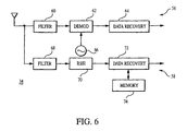
- the RF receiver 34 is operative to receive radio signals transmitted by the sending units or tire monitors 12. Structure and operation of the RF receiver 34 will be described below in greater detail in conjunction with FIG. 6 .
- Data conveyed on the RF signals and received by the RF receiver 34 is conveyed to the signal processor 36.
- the signal processor controls operation of the receiver 14 in response to data and instructions contained in memory such as the non-volatile memory 37.
- the signal processor controls the display 40 to provide an indication of conditions in the tire monitor system 10 ( FIG. 1 ).
- the signal processor 36 can automatically provide a display if the receive signals indicate tire pressure for one of the tires T(1)... T(4) is outside of a predetermined range.
- the learn mode switch 38 is used to place the receiving unit 14 in a learn mode, in which the receiving unit 14 automatically associates the identifiers of each of the sending units 12 associated with the vehicle V with respect to the tires. In learn mode, a particular learn signal or function code indicative of the learn mode is sent by the actuated tire monitor.
- the secondary modulation conveys information about the structure surrounding the wheel and tire monitor.
- FIG. 5 illustrates received signal strength at the RF receiver 34 as a function of circumferential wheel displacement for a vehicle wheel in the vicinity of a brake caliper.
- the receive signal strength is indicated as a relative displacement of the measured values from the center of the circle in FIG. 5 .
- a greater received signal strength is indicated by a point further from the center of the circle and, similarly, a lesser received signal strength is indicated by a point radially closer to the center of the circle.
- the data in FIG. 5 are experimentally obtained data for a left rear wheel on a vehicle with and without a brake caliper present, as indicated by the key in FIG. 5 .
- the characteristic pattern of FIG. 5 contains two nulls in received signal strength as the position of a tire monitor on the wheel progresses clockwise around the circumference of the wheel. Circumferential displacement of the tire monitor is indicated by the numbers on the perimeter of the circle. A first null 502 occurs at approximately 135 degrees angular displacement. A second null 504 indicates between 285 and 300 degrees angular displacement. These nulls represent dips or attenuations in received signal strength due to the presence of vehicle components such as metallic masses like brake calipers in the vicinity of the tire monitor mounted on the wheel as it rotates. In previous implementations of tire monitor systems, such variations in received signal strength have been considered to be noise or interference. However, the inventor has recognized that such patterns or variations may be associated with individual wheels to provide position location information for tire monitors on the vehicle.
- particular secondary variations unique to a particular tire monitor are associated with a particular wheel position.
- the position and identification information for the transmitting tire monitor can be associated with the transmitted tire data, such as tire pressure data.
- the secondary variations are unique to each wheel position on the vehicle and therefore uniquely identify the position of the tire with which the transmitted tire data is associated. Only the tire data need be transmitted, possibly with a mode signal or function code indicating learn mode or a normal mode of operation. This reduces the amount of data transmitted, reducing power consumption in the tire monitor and reducing noise in the radio environment of the system.
- the position of the transmitting tire monitor on the vehicle may be determined. If the currently received data correlates with a stored pattern of data, the position of the wheel on the vehicle matches the position associated with the stored data. If the correlation is poor, the position does not match.
- the position of the tire monitors 12 will have to be initialized in the receiving unit 14. This is accomplished by entering the learn mode, for example by magnetically actuating the magnet sensor 18 of the tire monitor 12. In other embodiments, this could be done by actuating a low-frequency (e.g., 150 kHz) transponder using radio frequency identification (RF ID) tag technology. In response to this actuation, the tire monitor sends a unique transmission indicating that it is in learn mode and that the receiving unit 14 may update position information stored for the actuated tire monitor.
- RF ID radio frequency identification
- unique components and structures may be placed at each wheel position to further control the signal transmission characteristic.
- a component may be positioned to create an additional null 506 in the received signal strength characteristic.
- yet another component may be placed to create another null 508 at another position in the received signal strength characteristic.
- the received signal strength will have a repeated pattern of variation due to motion of the transmitting tire monitor past the structures located in the vicinity of the wheel. These structures may reflect or redirect the transmitted signal power or they may absorb the transmit signal power, producing the nulls 502, 504, 506, 508 illustrated in FIG. 5 .
- unique structures are incorporated to modify the secondary modulation pattern at a wheel, preferably these unique structures are incorporated as features of existing components such as the brake caliper, the brake disk dust cover, etc.
- the added structure can be an additional component added to the wheel or strut assembly or any other structure within the vicinity of the wheel.
- the structure may be as simple as a piece of reflective tape positioned in the wheel well near the tire monitor.
- Such structures whether an inherent part of the vehicle such as the brake caliper or added to the vehicle to create a secondary variation, form modulation means positionable near the tire monitor 12 for imposing a secondary modulation on the radio signals transmitted by the tire monitor 12.
- FIG. 6 is a block diagram showing a proposed structure for the receiver 34 of FIG. 4 .
- the receiver 34 forms a receiving means for receiving radio signals transmitted by the tire monitors 12.
- the receiver 34 in the exemplary embodiment of FIG. 6 includes a first demodulation circuit 56 and a second demodulation circuit 58.
- the first demodulation circuit 56 includes a first filter 60, a demodulator 62 and a data recovery circuit 64 and a local oscillator 66.
- the second demodulation circuit 58 includes a second filter 68, a received signal strength indication circuit 70, a second data recovery circuit 72 and a memory 74.
- the first demodulation circuit 56 operates to receive the data signals transmitted by the tire monitors 12 at the wheels of the vehicle.
- the first demodulation circuit 56 demodulates the primary modulation of the radio signals.
- the filter 60 is typically a bandpass filter with a passband centered around the transmit frequency used by the tire monitors. Signals outside this passband are considered noise and are attenuated.
- the demodulator 62 in response to a carrier signal generated by the oscillator 66, demodulates the filtered signal produced by the filter 60. Any suitable modulation and demodulation scheme may be used in the tire monitor system 10.
- the demodulated data are provided by the demodulator 62 to the first data recovery circuit 64.
- the data recovery circuit 64 recovers the data including the digital variable ID(i) that contains the identification code assigned to the respective sending unit and the pressure variable P(i) which contains the measure of tire pressure transmitted by the tire monitor 12 ( FIG. 3 ).
- the demodulator 62 and the data recovery circuit 64 form a demodulation means for recovering the tire data from the radio signals.
- the identification code may not be transmitted and the secondary variations may be used by the receiver 34 to identify the tire data or to associate the tire data with a position on the vehicle. This recovered data is conveyed to the signal processor 36 of the receiving unit 14 containing the receiver 34.
- the second demodulation circuit 58 includes the filter 68, received signal strength indication (RSSI) circuit 70 and second data recovery circuit 72.
- This circuit 58 demodulates the secondary modulation data which defines position data for the transmitting time monitor 12.
- the filter 68 operates as a low pass filter to attenuate signals beyond the low frequency pass band suitable for detecting the secondary modulation information in the received signal. Since the frequency of modulation is related to wheel speed of the vehicle, this modulated information is received at a relatively low frequency.
- the RSSI circuit 70 detects the relative signal strength of the signal passed by the filter 68.
- This signal has a signal strength comparable to that illustrated in FIG. 5 .
- This signal has a relatively high amplitude values corresponding to portions of the circumferential travel of the tire monitor where its transmitted signal is not attenuated or reflected.
- this signal will have portions such as the nulls 502, 504, 506, 508 ( FIG. 5 ) where, during the circumferential travel of the tire monitor 12, its signal is attenuated, or absorbed or reflected, limiting reception by the receiver 34.
- Suitable received signal strength indication circuits are well known.
- the RSSI circuit 70 provides a received signal strength indication to the data recovery circuit 72.
- the data recovery circuit 72 detects a bit pattern or data pattern corresponding to position data for the transmitting time monitor 12 which originated the transmission.
- the data recover circuit 72 compares the received position data with stored position from the memory 74.
- the stored position data is previously learned and stored during a learn mode operation of the tire monitor system 10.
- the data recovery circuit 72 compares the received position data with the stored position data. If a match occurs, the receiver 14 has received tire data from a known tire monitor of the tire monitor system 10. If no match occurs, the received position data is noise or transmission from a tire monitor in another tire monitor system on an adjacent vehicle. Other techniques for data recovery may be used.
- the data recovery circuit 72 forms an identification circuit responsive to the secondary variations of the received carrier signal to identify a particular wheel location based on the secondary variations.
- the RSSI circuit 70 and the data recovery circuit 72 form a decoding means responsive to secondary modulation of the radio signals received by the receiver for associating the tire data with respective wheel locations of the vehicle V.
- the transmitted data will appear as a series of data bits having proportional characteristics.
- the duration of these data bits is a direct function of the wheel speed. That is, the duration is not an absolute value but will vary with time, being of shorter duration when the wheel and the vehicle are moving faster and of longer duration when the wheel and vehicle are moving more slowly.
- the data recovery circuit 72 preferably implements a ratiometric decoder which detects data based on the relative size or duration of received data bits to distinguish a logical one bit from a logical 0 bit.
- an improved tire monitor system for a vehicle such as an automobile
- transmits data from an automobile road wheel assembly via radio frequency communication Through the monitoring and control of secondary modulation of the transmitted signal, signal variations which had previously been treated as noise or interference are instead used to provide self association between the identity of the transmitting tire monitor and the physical wheel location on the vehicle. This is accomplished without modification to the existing sensor and transmitter of the time monitor. Since the tire monitor is necessarily a cost sensitive item, this is a significant advantage.
Landscapes
- Engineering & Computer Science (AREA)
- Mechanical Engineering (AREA)
- Measuring Fluid Pressure (AREA)
- Arrangements For Transmission Of Measured Signals (AREA)
Claims (11)
- Drahtloses Reifenüberwachungssystem (10), umfassend eine Vielzahl von Reifenmonitoren (12), die den Rädern (T(1), T(2), T(3), T(4)) eines Fahrzeugs (V) zugeordnet und so konfiguriert sind, dass sie Funksignale mit Reifendaten (26) übertragen, und einen Empfänger (14), der so konfiguriert ist, dass er die Funksignale empfängt, wobei der Empfänger einen Schaltkreis (58) umfasst, der sekundäre Änderungen in den Funksignalen, hervorgerufen durch die Bewegung der Vielzahl von Reifenmonitoren, detektiert, wobei das drahtlose Reifenüberwachungssystem dadurch gekennzeichnet ist, dass:eine oder mehrere Modulationskomponenten vorgesehen sind, positionierbar in der Nähe des entsprechenden Reifenmonitors bei jedem Rad, um in Verbindung mit Variationen in der Signalcharakteristik, hervorgerufen durch Fahrzeugkomponenten und -strukturen, den Funksignalen die sekundären Variationen aufzumodulieren.
- Drahtloses Reifenüberwachungssystem nach Anspruch 1, dadurch gekennzeichnet, dass die eine oder mehrere Komponenten metallische Elemente umfassen, die entlang der Umfangspfade der Reifenmonitoren auf den Rädern des Fahrzeugs positionierbar sind, um die vom Empfänger empfangenen Funksignale zu verändern.
- Drahtloses Reifenüberwachungssystem nach Anspruch 1, ferner dadurch gekennzeichnet, dass der Empfänger einen Identifizierungsschaltkreis (72) enthält, der auf die zweiten Variationen anspricht, um, basierend auf den zweiten Variationen, eine spezielle Radposition zu identifizieren.
- Drahtloses Reifenüberwachungssystem nach Anspruch 3, dadurch gekennzeichnet, dass der Empfänger ferner einen Decoder (70, 72) enthält, der die Positionsdaten in den zweiten Variationen detektiert.
- Drahtloses Reifenüberwachungssystem nach Anspruch 4, dadurch gekennzeichnet, dass der Decoder einen ratiometrischen Decoder enthält, der auf die relative Dauer von Bits der Dauerdaten anspricht, um die Positionsdaten zu decodieren.
- Drahtloses Reifenüberwachungssystem nach Anspruch 3, dadurch gekennzeichnet, dass der Empfänger ferner einen Demodulator (56) enthält, der die Funksignale demoduliert, um die Reifendaten zu empfangen.
- Drahtloses Reifenüberwachungssystem (10), umfassend Reifenüberwachungsmittel (12), die an den jeweiligen Rädern (T(1), T(2), T(3), T(4)) eines Fahrzeugs (V) positioniert und um mit den Reifendaten (26) modulierte Funksignale zu übertragen, und ein Empfangsmittel (14), um die Funksignale zu empfangen, wobei das Empfangsmittel ein Demodulationsmittel (56) umfasst, um aus den Funksignalen die Reifendaten zurückzugewinnen, wobei das drahtlose Reifenüberwachungssystem dadurch gekennzeichnet ist, dass:Modulationsmittel vorgesehen sind, die in der Nähe der Reifenüberwachungsmittel positionierbar sind, um in Verbindung mit Variationen in der Signalcharakteristik, hervorgerufen durch Fahrzeugkomponenten und -strukturen, den Funksignalen eine zweite Modulation aufzumodulieren, undein Decodierungsmittel (70, 72) der Empfangsmittel, das auf die sekundäre Modulation anspricht, um die Reifendaten mit den entsprechenden Radpositionen des Fahrzeugs zu assoziieren.
- Drahtloses Reifenüberwachungssystem nach Anspruch 7, dadurch gekennzeichnet, dass das Reifenüberwachungsmittel gekennzeichnet ist, durch eine Mehrzahl von drahtlosen Reifenmonitoren, die an den entsprechenden Rädern des Fahrzeugs montiert sind, um einen Reifenzustand zu überwachen und die Reifendaten zu erzeugen, wobei jeder drahtlose Reifenmonitor entsprechende Funksignale überträgt.
- Drahtloses Reifenüberwachungssystem nach Anspruch 8, dadurch gekennzeichnet, dass das Modulationsmittel Gruppierungen von einer oder mehreren Komponenten umfasst, die nahe dem Umfangspfad des entsprechenden Reifenmonitors montierbar sind, wobei jede Gruppierung eine einzigartige sekundäre Modulation auf den von dem entsprechenden Reifenmonitor ausgesendeten Funksignalen erzeugt.
- Drahtloses Reifenüberwachungssystem nach Anspruch 8, dadurch gekennzeichnet, dass das Modulationsmittel dadurch gekennzeichnet ist, dass Änderungsmittel vorgesehen sind, um die Funksignale selektiv zu absorbieren und zu reflektieren.
- Drahtloses Reifenüberwachungssystem nach Anspruch 7, dadurch gekennzeichnet, dass das Decodierungsmittel durch einen ratiometrischen Decoder charakterisiert ist, der auf die relative Dauer der sekundären Modulation anspricht, um die Positionsdaten zu decodieren, um das Reifenüberwachungsmittel mit den entsprechenden Rädern des Fahrzeugs zu assoziieren.
Priority Applications (4)
| Application Number | Priority Date | Filing Date | Title |
|---|---|---|---|
| EP02251436A EP1340629B1 (de) | 2002-02-28 | 2002-02-28 | Verfahren und Vorrichtung zur Identifikation von entfernten Sendeeinheiten in einem Reifendrucküberwachungssystem von einem Fahrzeug mit Sekundärmodulation von der Radumdrehung |
| ES02251436T ES2306749T3 (es) | 2002-02-28 | 2002-02-28 | Metodo y aparato para identificar las unidades de transmision remota en un sistema de monitorizacion de la presion de los neumaticos de un vehiculo usando la modulacion secundaria de la rotacion de la rueda. |
| DE60227045T DE60227045D1 (de) | 2002-02-28 | 2002-02-28 | Verfahren und Vorrichtung zur Identifikation von entfernten Sendeeinheiten in einem Reifendrucküberwachungssystem von einem Fahrzeug mit Sekundärmodulation von der Radumdrehung |
| AT02251436T ATE398031T1 (de) | 2002-02-28 | 2002-02-28 | Verfahren und vorrichtung zur identifikation von entfernten sendeeinheiten in einem reifendrucküberwachungssystem von einem fahrzeug mit sekundärmodulation von der radumdrehung |
Applications Claiming Priority (1)
| Application Number | Priority Date | Filing Date | Title |
|---|---|---|---|
| EP02251436A EP1340629B1 (de) | 2002-02-28 | 2002-02-28 | Verfahren und Vorrichtung zur Identifikation von entfernten Sendeeinheiten in einem Reifendrucküberwachungssystem von einem Fahrzeug mit Sekundärmodulation von der Radumdrehung |
Publications (2)
| Publication Number | Publication Date |
|---|---|
| EP1340629A1 EP1340629A1 (de) | 2003-09-03 |
| EP1340629B1 true EP1340629B1 (de) | 2008-06-11 |
Family
ID=27675755
Family Applications (1)
| Application Number | Title | Priority Date | Filing Date |
|---|---|---|---|
| EP02251436A Expired - Lifetime EP1340629B1 (de) | 2002-02-28 | 2002-02-28 | Verfahren und Vorrichtung zur Identifikation von entfernten Sendeeinheiten in einem Reifendrucküberwachungssystem von einem Fahrzeug mit Sekundärmodulation von der Radumdrehung |
Country Status (4)
| Country | Link |
|---|---|
| EP (1) | EP1340629B1 (de) |
| AT (1) | ATE398031T1 (de) |
| DE (1) | DE60227045D1 (de) |
| ES (1) | ES2306749T3 (de) |
Cited By (9)
| Publication number | Priority date | Publication date | Assignee | Title |
|---|---|---|---|---|
| US8502655B2 (en) | 2011-08-09 | 2013-08-06 | Continental Automotive Systems, Inc. | Protocol misinterpretation avoidance apparatus and method for a tire pressure monitoring system |
| US8576060B2 (en) | 2011-08-09 | 2013-11-05 | Continental Automotive Systems, Inc. | Protocol arrangement in a tire pressure monitoring system |
| US8692661B2 (en) | 2007-07-03 | 2014-04-08 | Continental Automotive Systems, Inc. | Universal tire pressure monitoring sensor |
| US8742914B2 (en) | 2011-08-09 | 2014-06-03 | Continental Automotive Systems, Inc. | Tire pressure monitoring apparatus and method |
| US8751092B2 (en) | 2011-01-13 | 2014-06-10 | Continental Automotive Systems, Inc. | Protocol protection |
| US9024743B2 (en) | 2011-08-09 | 2015-05-05 | Continental Automotive System, Inc. | Apparatus and method for activating a localization process for a tire pressure monitor |
| US9446636B2 (en) | 2014-02-26 | 2016-09-20 | Continental Automotive Systems, Inc. | Pressure check tool and method of operating the same |
| US9517664B2 (en) | 2015-02-20 | 2016-12-13 | Continental Automotive Systems, Inc. | RF transmission method and apparatus in a tire pressure monitoring system |
| US10220660B2 (en) | 2015-08-03 | 2019-03-05 | Continental Automotive Systems, Inc. | Apparatus, system and method for configuring a tire information sensor with a transmission protocol based on vehicle trigger characteristics |
Families Citing this family (5)
| Publication number | Priority date | Publication date | Assignee | Title |
|---|---|---|---|---|
| DE102004033732A1 (de) * | 2004-07-13 | 2006-02-16 | Adam Opel Ag | Verfahren und System zur Positionserkennung von Radmodulen an einem Kraftfahrzeug |
| US7817023B2 (en) * | 2004-12-15 | 2010-10-19 | The Yokohama Rubber Co., Ltd. | Wheel information acquiring system |
| FR2916564B1 (fr) * | 2007-05-25 | 2010-09-17 | Siemens Vdo Automotive | Procede et dispositif de localisation des roues d'un vehicule. |
| JP4412361B2 (ja) * | 2007-07-11 | 2010-02-10 | 株式会社デンソー | 車輪位置検出装置、それを備えたタイヤ空気圧検出装置および送受信機 |
| US9676238B2 (en) | 2011-08-09 | 2017-06-13 | Continental Automotive Systems, Inc. | Tire pressure monitor system apparatus and method |
Family Cites Families (5)
| Publication number | Priority date | Publication date | Assignee | Title |
|---|---|---|---|---|
| US5600301A (en) | 1993-03-11 | 1997-02-04 | Schrader Automotive Inc. | Remote tire pressure monitoring system employing coded tire identification and radio frequency transmission, and enabling recalibration upon tire rotation or replacement |
| US5483827A (en) | 1994-06-03 | 1996-01-16 | Computer Methods Corporation | Active integrated circuit transponder and sensor apparatus for sensing and transmitting vehicle tire parameter data |
| US5661651A (en) | 1995-03-31 | 1997-08-26 | Prince Corporation | Wireless vehicle parameter monitoring system |
| DE19652365C1 (de) * | 1996-12-17 | 1998-04-02 | Albert Thorp Gmbh | Verfahren zum Erkennen, an welcher Stelle eines mit einer Reifendruckkontrolleinrichtung ausgerüsteten Fahrzeuges sich ein bestimmtes Rad befindet |
| FR2774178B1 (fr) * | 1998-01-23 | 2000-02-25 | Sagem | Procede de localisation et de reconnaissance de la position des roues sur un vehicule |
-
2002
- 2002-02-28 DE DE60227045T patent/DE60227045D1/de not_active Expired - Lifetime
- 2002-02-28 EP EP02251436A patent/EP1340629B1/de not_active Expired - Lifetime
- 2002-02-28 ES ES02251436T patent/ES2306749T3/es not_active Expired - Lifetime
- 2002-02-28 AT AT02251436T patent/ATE398031T1/de not_active IP Right Cessation
Cited By (11)
| Publication number | Priority date | Publication date | Assignee | Title |
|---|---|---|---|---|
| US8692661B2 (en) | 2007-07-03 | 2014-04-08 | Continental Automotive Systems, Inc. | Universal tire pressure monitoring sensor |
| US8742913B2 (en) | 2007-07-03 | 2014-06-03 | Continental Automotive Systems, Inc. | Method of preparing a universal tire pressure monitoring sensor |
| US8751092B2 (en) | 2011-01-13 | 2014-06-10 | Continental Automotive Systems, Inc. | Protocol protection |
| US8502655B2 (en) | 2011-08-09 | 2013-08-06 | Continental Automotive Systems, Inc. | Protocol misinterpretation avoidance apparatus and method for a tire pressure monitoring system |
| US8576060B2 (en) | 2011-08-09 | 2013-11-05 | Continental Automotive Systems, Inc. | Protocol arrangement in a tire pressure monitoring system |
| US8742914B2 (en) | 2011-08-09 | 2014-06-03 | Continental Automotive Systems, Inc. | Tire pressure monitoring apparatus and method |
| US9024743B2 (en) | 2011-08-09 | 2015-05-05 | Continental Automotive System, Inc. | Apparatus and method for activating a localization process for a tire pressure monitor |
| US9259980B2 (en) | 2011-08-09 | 2016-02-16 | Continental Automotive Systems, Inc. | Apparatus and method for data transmissions in a tire pressure monitor |
| US9446636B2 (en) | 2014-02-26 | 2016-09-20 | Continental Automotive Systems, Inc. | Pressure check tool and method of operating the same |
| US9517664B2 (en) | 2015-02-20 | 2016-12-13 | Continental Automotive Systems, Inc. | RF transmission method and apparatus in a tire pressure monitoring system |
| US10220660B2 (en) | 2015-08-03 | 2019-03-05 | Continental Automotive Systems, Inc. | Apparatus, system and method for configuring a tire information sensor with a transmission protocol based on vehicle trigger characteristics |
Also Published As
| Publication number | Publication date |
|---|---|
| EP1340629A1 (de) | 2003-09-03 |
| ATE398031T1 (de) | 2008-07-15 |
| DE60227045D1 (de) | 2008-07-24 |
| ES2306749T3 (es) | 2008-11-16 |
Similar Documents
| Publication | Publication Date | Title |
|---|---|---|
| US6417766B1 (en) | Method and apparatus for identifying remote sending units in a tire pressure monitor system of a vehicle using secondary modulation of wheel rotation | |
| EP1340629A1 (de) | Verfahren und Vorrichtung zur Identifikation von entfernten Sendeeinheiten in einem Reifendrucküberwachungssystem von einem Fahrzeug mit Sekundärmodulation von der Radumdrehung | |
| EP2018980B1 (de) | Reifenlokalisierungssystem | |
| US6463798B2 (en) | Tire inflation pressure monitoring and location determining method and apparatus | |
| EP1494877B1 (de) | Bestimmung der rad-sensor-position mittels beschleunigungssignale | |
| CA2604706C (en) | Determination of wheel sensor position using a single radio frequency detector in an automotive remote tire monitor system | |
| US6788193B2 (en) | System and method for tire pressure monitoring providing automatic tire location recognition | |
| US7019628B2 (en) | Tire monitoring and keyless entry system | |
| US6018993A (en) | Method for monitoring tire pressure | |
| US6864785B2 (en) | Determination of wheel sensor position using radio frequency detectors in an automotive remote tire monitor system | |
| US7102498B2 (en) | Remote keyless entry system with two modes of demodulation | |
| GB2382147A (en) | Automatic tyre location recognition for a tyre pressure monitoring system | |
| WO1994006640A1 (en) | Tyre condition monitoring | |
| US7154414B2 (en) | System and method for remote tire pressure monitoring | |
| GB2385929A (en) | A system for identifying tyre location | |
| US6725712B1 (en) | System and method for tire pressure monitoring with automatic tire location recognition | |
| US20060158324A1 (en) | System and method to facilitate idetifying location of a remote module | |
| EP1270276B1 (de) | Reifenüberwachungsgerät | |
| JP2002131165A (ja) | タイヤ空気圧警報装置およびその受信装置 | |
| JPH08244424A (ja) | タイヤ圧力モニタシステム | |
| JP2003272080A (ja) | 車輪回転の二次的変調を用いて車両のタイヤ圧力監視システムの遠隔送信ユニットを特定するための方法及び装置 | |
| JP2006123725A (ja) | タイヤ空気圧モニター装置 | |
| JP3952956B2 (ja) | タイヤ空気圧モニター装置 | |
| JP2005145113A (ja) | タイヤ位置検出装置 | |
| KR20060016447A (ko) | 타이어 압력 모니터링 시스템에서의 타이어 위치 자동인식 시스템 및 그의 방법 |
Legal Events
| Date | Code | Title | Description |
|---|---|---|---|
| PUAI | Public reference made under article 153(3) epc to a published international application that has entered the european phase |
Free format text: ORIGINAL CODE: 0009012 |
|
| AK | Designated contracting states |
Kind code of ref document: A1 Designated state(s): AT BE CH CY DE DK ES FI FR GB GR IE IT LI LU MC NL PT SE TR |
|
| AX | Request for extension of the european patent |
Extension state: AL LT LV MK RO SI |
|
| 17P | Request for examination filed |
Effective date: 20040123 |
|
| AKX | Designation fees paid |
Designated state(s): AT BE CH CY DE DK ES FI FR GB GR IE IT LI LU MC NL PT SE TR |
|
| AXX | Extension fees paid |
Extension state: AL Payment date: 20040123 Extension state: LT Payment date: 20040123 Extension state: SI Payment date: 20040123 Extension state: LV Payment date: 20040123 Extension state: RO Payment date: 20040123 Extension state: MK Payment date: 20040123 |
|
| GRAP | Despatch of communication of intention to grant a patent |
Free format text: ORIGINAL CODE: EPIDOSNIGR1 |
|
| GRAS | Grant fee paid |
Free format text: ORIGINAL CODE: EPIDOSNIGR3 |
|
| GRAA | (expected) grant |
Free format text: ORIGINAL CODE: 0009210 |
|
| AK | Designated contracting states |
Kind code of ref document: B1 Designated state(s): AT BE CH CY DE DK ES FI FR GB GR IE IT LI LU MC NL PT SE TR |
|
| AX | Request for extension of the european patent |
Extension state: AL LT LV MK RO SI |
|
| REG | Reference to a national code |
Ref country code: GB Ref legal event code: FG4D |
|
| REG | Reference to a national code |
Ref country code: CH Ref legal event code: EP |
|
| REF | Corresponds to: |
Ref document number: 60227045 Country of ref document: DE Date of ref document: 20080724 Kind code of ref document: P |
|
| REG | Reference to a national code |
Ref country code: IE Ref legal event code: FG4D |
|
| REG | Reference to a national code |
Ref country code: SE Ref legal event code: TRGR |
|
| PG25 | Lapsed in a contracting state [announced via postgrant information from national office to epo] |
Ref country code: FI Free format text: LAPSE BECAUSE OF FAILURE TO SUBMIT A TRANSLATION OF THE DESCRIPTION OR TO PAY THE FEE WITHIN THE PRESCRIBED TIME-LIMIT Effective date: 20080611 |
|
| REG | Reference to a national code |
Ref country code: ES Ref legal event code: FG2A Ref document number: 2306749 Country of ref document: ES Kind code of ref document: T3 |
|
| PG25 | Lapsed in a contracting state [announced via postgrant information from national office to epo] |
Ref country code: AT Free format text: LAPSE BECAUSE OF FAILURE TO SUBMIT A TRANSLATION OF THE DESCRIPTION OR TO PAY THE FEE WITHIN THE PRESCRIBED TIME-LIMIT Effective date: 20080611 Ref country code: NL Free format text: LAPSE BECAUSE OF FAILURE TO SUBMIT A TRANSLATION OF THE DESCRIPTION OR TO PAY THE FEE WITHIN THE PRESCRIBED TIME-LIMIT Effective date: 20080611 |
|
| NLV1 | Nl: lapsed or annulled due to failure to fulfill the requirements of art. 29p and 29m of the patents act | ||
| PG25 | Lapsed in a contracting state [announced via postgrant information from national office to epo] |
Ref country code: PT Free format text: LAPSE BECAUSE OF FAILURE TO SUBMIT A TRANSLATION OF THE DESCRIPTION OR TO PAY THE FEE WITHIN THE PRESCRIBED TIME-LIMIT Effective date: 20081111 |
|
| PG25 | Lapsed in a contracting state [announced via postgrant information from national office to epo] |
Ref country code: BE Free format text: LAPSE BECAUSE OF FAILURE TO SUBMIT A TRANSLATION OF THE DESCRIPTION OR TO PAY THE FEE WITHIN THE PRESCRIBED TIME-LIMIT Effective date: 20080611 |
|
| PLBE | No opposition filed within time limit |
Free format text: ORIGINAL CODE: 0009261 |
|
| STAA | Information on the status of an ep patent application or granted ep patent |
Free format text: STATUS: NO OPPOSITION FILED WITHIN TIME LIMIT |
|
| PG25 | Lapsed in a contracting state [announced via postgrant information from national office to epo] |
Ref country code: DK Free format text: LAPSE BECAUSE OF FAILURE TO SUBMIT A TRANSLATION OF THE DESCRIPTION OR TO PAY THE FEE WITHIN THE PRESCRIBED TIME-LIMIT Effective date: 20080611 |
|
| 26N | No opposition filed |
Effective date: 20090312 |
|
| PG25 | Lapsed in a contracting state [announced via postgrant information from national office to epo] |
Ref country code: MC Free format text: LAPSE BECAUSE OF NON-PAYMENT OF DUE FEES Effective date: 20090228 |
|
| REG | Reference to a national code |
Ref country code: CH Ref legal event code: PL |
|
| PG25 | Lapsed in a contracting state [announced via postgrant information from national office to epo] |
Ref country code: LI Free format text: LAPSE BECAUSE OF NON-PAYMENT OF DUE FEES Effective date: 20090228 Ref country code: CH Free format text: LAPSE BECAUSE OF NON-PAYMENT OF DUE FEES Effective date: 20090228 |
|
| REG | Reference to a national code |
Ref country code: IE Ref legal event code: MM4A |
|
| PG25 | Lapsed in a contracting state [announced via postgrant information from national office to epo] |
Ref country code: IE Free format text: LAPSE BECAUSE OF NON-PAYMENT OF DUE FEES Effective date: 20090228 |
|
| PG25 | Lapsed in a contracting state [announced via postgrant information from national office to epo] |
Ref country code: GR Free format text: LAPSE BECAUSE OF FAILURE TO SUBMIT A TRANSLATION OF THE DESCRIPTION OR TO PAY THE FEE WITHIN THE PRESCRIBED TIME-LIMIT Effective date: 20080912 |
|
| PG25 | Lapsed in a contracting state [announced via postgrant information from national office to epo] |
Ref country code: LU Free format text: LAPSE BECAUSE OF NON-PAYMENT OF DUE FEES Effective date: 20090228 |
|
| PG25 | Lapsed in a contracting state [announced via postgrant information from national office to epo] |
Ref country code: TR Free format text: LAPSE BECAUSE OF FAILURE TO SUBMIT A TRANSLATION OF THE DESCRIPTION OR TO PAY THE FEE WITHIN THE PRESCRIBED TIME-LIMIT Effective date: 20080611 |
|
| PG25 | Lapsed in a contracting state [announced via postgrant information from national office to epo] |
Ref country code: CY Free format text: LAPSE BECAUSE OF FAILURE TO SUBMIT A TRANSLATION OF THE DESCRIPTION OR TO PAY THE FEE WITHIN THE PRESCRIBED TIME-LIMIT Effective date: 20080611 |
|
| PGFP | Annual fee paid to national office [announced via postgrant information from national office to epo] |
Ref country code: DE Payment date: 20140227 Year of fee payment: 13 Ref country code: SE Payment date: 20140227 Year of fee payment: 13 |
|
| PGFP | Annual fee paid to national office [announced via postgrant information from national office to epo] |
Ref country code: FR Payment date: 20140128 Year of fee payment: 13 Ref country code: IT Payment date: 20140226 Year of fee payment: 13 Ref country code: ES Payment date: 20140226 Year of fee payment: 13 |
|
| PGFP | Annual fee paid to national office [announced via postgrant information from national office to epo] |
Ref country code: GB Payment date: 20140128 Year of fee payment: 13 |
|
| REG | Reference to a national code |
Ref country code: DE Ref legal event code: R119 Ref document number: 60227045 Country of ref document: DE |
|
| GBPC | Gb: european patent ceased through non-payment of renewal fee |
Effective date: 20150228 |
|
| REG | Reference to a national code |
Ref country code: FR Ref legal event code: ST Effective date: 20151030 |
|
| PG25 | Lapsed in a contracting state [announced via postgrant information from national office to epo] |
Ref country code: SE Free format text: LAPSE BECAUSE OF NON-PAYMENT OF DUE FEES Effective date: 20150301 |
|
| REG | Reference to a national code |
Ref country code: SE Ref legal event code: EUG |
|
| PG25 | Lapsed in a contracting state [announced via postgrant information from national office to epo] |
Ref country code: IT Free format text: LAPSE BECAUSE OF NON-PAYMENT OF DUE FEES Effective date: 20150228 |
|
| PG25 | Lapsed in a contracting state [announced via postgrant information from national office to epo] |
Ref country code: DE Free format text: LAPSE BECAUSE OF NON-PAYMENT OF DUE FEES Effective date: 20150901 Ref country code: GB Free format text: LAPSE BECAUSE OF NON-PAYMENT OF DUE FEES Effective date: 20150228 |
|
| PG25 | Lapsed in a contracting state [announced via postgrant information from national office to epo] |
Ref country code: FR Free format text: LAPSE BECAUSE OF NON-PAYMENT OF DUE FEES Effective date: 20150302 |
|
| REG | Reference to a national code |
Ref country code: ES Ref legal event code: FD2A Effective date: 20160331 |
|
| PG25 | Lapsed in a contracting state [announced via postgrant information from national office to epo] |
Ref country code: ES Free format text: LAPSE BECAUSE OF NON-PAYMENT OF DUE FEES Effective date: 20150301 |