EP1342501A2 - Knetmaschine für Teigmittel, insbesondere für Backwaren - Google Patents
Knetmaschine für Teigmittel, insbesondere für Backwaren Download PDFInfo
- Publication number
- EP1342501A2 EP1342501A2 EP03003912A EP03003912A EP1342501A2 EP 1342501 A2 EP1342501 A2 EP 1342501A2 EP 03003912 A EP03003912 A EP 03003912A EP 03003912 A EP03003912 A EP 03003912A EP 1342501 A2 EP1342501 A2 EP 1342501A2
- Authority
- EP
- European Patent Office
- Prior art keywords
- kneading
- bowl
- arms
- arm
- machine according
- Prior art date
- Legal status (The legal status is an assumption and is not a legal conclusion. Google has not performed a legal analysis and makes no representation as to the accuracy of the status listed.)
- Withdrawn
Links
Images




Classifications
-
- A—HUMAN NECESSITIES
- A21—BAKING; EDIBLE DOUGHS
- A21C—MACHINES OR EQUIPMENT FOR MAKING OR PROCESSING DOUGHS; HANDLING BAKED ARTICLES MADE FROM DOUGH
- A21C1/00—Mixing or kneading machines for the preparation of dough
- A21C1/02—Mixing or kneading machines for the preparation of dough with vertically-mounted tools; Machines for whipping or beating
-
- A—HUMAN NECESSITIES
- A21—BAKING; EDIBLE DOUGHS
- A21C—MACHINES OR EQUIPMENT FOR MAKING OR PROCESSING DOUGHS; HANDLING BAKED ARTICLES MADE FROM DOUGH
- A21C1/00—Mixing or kneading machines for the preparation of dough
- A21C1/14—Structural elements of mixing or kneading machines; Parts; Accessories
- A21C1/1405—Tools
-
- B—PERFORMING OPERATIONS; TRANSPORTING
- B01—PHYSICAL OR CHEMICAL PROCESSES OR APPARATUS IN GENERAL
- B01F—MIXING, e.g. DISSOLVING, EMULSIFYING OR DISPERSING
- B01F27/00—Mixers with rotary stirring devices in fixed receptacles; Kneaders
- B01F27/05—Stirrers
- B01F27/11—Stirrers characterised by the configuration of the stirrers
- B01F27/112—Stirrers characterised by the configuration of the stirrers with arms, paddles, vanes or blades
- B01F27/1126—Stirrers characterised by the configuration of the stirrers with arms, paddles, vanes or blades the stirrer being a bent rod supported at one end only
-
- B—PERFORMING OPERATIONS; TRANSPORTING
- B01—PHYSICAL OR CHEMICAL PROCESSES OR APPARATUS IN GENERAL
- B01F—MIXING, e.g. DISSOLVING, EMULSIFYING OR DISPERSING
- B01F27/00—Mixers with rotary stirring devices in fixed receptacles; Kneaders
- B01F27/80—Mixers with rotary stirring devices in fixed receptacles; Kneaders with stirrers rotating about a substantially vertical axis
- B01F27/805—Mixers with rotary stirring devices in fixed receptacles; Kneaders with stirrers rotating about a substantially vertical axis wherein the stirrers or the receptacles are moved in order to bring them into operative position; Means for fixing the receptacle
- B01F27/806—Mixers with rotary stirring devices in fixed receptacles; Kneaders with stirrers rotating about a substantially vertical axis wherein the stirrers or the receptacles are moved in order to bring them into operative position; Means for fixing the receptacle with vertical displacement of the stirrer, e.g. in combination with means for pivoting the stirrer about a vertical axis in order to co-operate with different receptacles
-
- B—PERFORMING OPERATIONS; TRANSPORTING
- B01—PHYSICAL OR CHEMICAL PROCESSES OR APPARATUS IN GENERAL
- B01F—MIXING, e.g. DISSOLVING, EMULSIFYING OR DISPERSING
- B01F27/00—Mixers with rotary stirring devices in fixed receptacles; Kneaders
- B01F27/80—Mixers with rotary stirring devices in fixed receptacles; Kneaders with stirrers rotating about a substantially vertical axis
- B01F27/85—Mixers with rotary stirring devices in fixed receptacles; Kneaders with stirrers rotating about a substantially vertical axis with two or more stirrers on separate shafts
-
- B—PERFORMING OPERATIONS; TRANSPORTING
- B01—PHYSICAL OR CHEMICAL PROCESSES OR APPARATUS IN GENERAL
- B01F—MIXING, e.g. DISSOLVING, EMULSIFYING OR DISPERSING
- B01F27/00—Mixers with rotary stirring devices in fixed receptacles; Kneaders
- B01F27/80—Mixers with rotary stirring devices in fixed receptacles; Kneaders with stirrers rotating about a substantially vertical axis
- B01F27/90—Mixers with rotary stirring devices in fixed receptacles; Kneaders with stirrers rotating about a substantially vertical axis with paddles or arms
- B01F27/902—Mixers with rotary stirring devices in fixed receptacles; Kneaders with stirrers rotating about a substantially vertical axis with paddles or arms cooperating with intermeshing elements fixed on the receptacle walls
- B01F27/9021—Mixers with rotary stirring devices in fixed receptacles; Kneaders with stirrers rotating about a substantially vertical axis with paddles or arms cooperating with intermeshing elements fixed on the receptacle walls the elements being vertically arranged, e.g. fixed on the bottom
-
- B—PERFORMING OPERATIONS; TRANSPORTING
- B01—PHYSICAL OR CHEMICAL PROCESSES OR APPARATUS IN GENERAL
- B01F—MIXING, e.g. DISSOLVING, EMULSIFYING OR DISPERSING
- B01F29/00—Mixers with rotating receptacles
- B01F29/80—Mixers with rotating receptacles rotating about a substantially vertical axis
- B01F29/83—Mixers with rotating receptacles rotating about a substantially vertical axis with rotary paddles or arms, e.g. movable out of the receptacle
-
- B—PERFORMING OPERATIONS; TRANSPORTING
- B01—PHYSICAL OR CHEMICAL PROCESSES OR APPARATUS IN GENERAL
- B01F—MIXING, e.g. DISSOLVING, EMULSIFYING OR DISPERSING
- B01F2215/00—Auxiliary or complementary information in relation with mixing
- B01F2215/04—Technical information in relation with mixing
- B01F2215/0413—Numerical information
- B01F2215/0418—Geometrical information
- B01F2215/0422—Numerical values of angles
-
- B—PERFORMING OPERATIONS; TRANSPORTING
- B01—PHYSICAL OR CHEMICAL PROCESSES OR APPARATUS IN GENERAL
- B01F—MIXING, e.g. DISSOLVING, EMULSIFYING OR DISPERSING
- B01F27/00—Mixers with rotary stirring devices in fixed receptacles; Kneaders
- B01F27/05—Stirrers
- B01F27/07—Stirrers characterised by their mounting on the shaft
- B01F27/072—Stirrers characterised by their mounting on the shaft characterised by the disposition of the stirrers with respect to the rotating axis
- B01F27/0721—Stirrers characterised by their mounting on the shaft characterised by the disposition of the stirrers with respect to the rotating axis parallel with respect to the rotating axis
-
- B—PERFORMING OPERATIONS; TRANSPORTING
- B01—PHYSICAL OR CHEMICAL PROCESSES OR APPARATUS IN GENERAL
- B01F—MIXING, e.g. DISSOLVING, EMULSIFYING OR DISPERSING
- B01F27/00—Mixers with rotary stirring devices in fixed receptacles; Kneaders
- B01F27/05—Stirrers
- B01F27/11—Stirrers characterised by the configuration of the stirrers
- B01F27/112—Stirrers characterised by the configuration of the stirrers with arms, paddles, vanes or blades
- B01F27/1123—Stirrers characterised by the configuration of the stirrers with arms, paddles, vanes or blades sickle-shaped, i.e. curved in at least one direction
-
- B—PERFORMING OPERATIONS; TRANSPORTING
- B01—PHYSICAL OR CHEMICAL PROCESSES OR APPARATUS IN GENERAL
- B01F—MIXING, e.g. DISSOLVING, EMULSIFYING OR DISPERSING
- B01F27/00—Mixers with rotary stirring devices in fixed receptacles; Kneaders
- B01F27/05—Stirrers
- B01F27/11—Stirrers characterised by the configuration of the stirrers
- B01F27/112—Stirrers characterised by the configuration of the stirrers with arms, paddles, vanes or blades
- B01F27/1125—Stirrers characterised by the configuration of the stirrers with arms, paddles, vanes or blades with vanes or blades extending parallel or oblique to the stirrer axis
-
- B—PERFORMING OPERATIONS; TRANSPORTING
- B01—PHYSICAL OR CHEMICAL PROCESSES OR APPARATUS IN GENERAL
- B01F—MIXING, e.g. DISSOLVING, EMULSIFYING OR DISPERSING
- B01F27/00—Mixers with rotary stirring devices in fixed receptacles; Kneaders
- B01F27/23—Mixers with rotary stirring devices in fixed receptacles; Kneaders characterised by the orientation or disposition of the rotor axis
- B01F27/232—Mixers with rotary stirring devices in fixed receptacles; Kneaders characterised by the orientation or disposition of the rotor axis with two or more rotation axes
- B01F27/2321—Mixers with rotary stirring devices in fixed receptacles; Kneaders characterised by the orientation or disposition of the rotor axis with two or more rotation axes having different inclinations, e.g. non parallel
-
- B—PERFORMING OPERATIONS; TRANSPORTING
- B01—PHYSICAL OR CHEMICAL PROCESSES OR APPARATUS IN GENERAL
- B01F—MIXING, e.g. DISSOLVING, EMULSIFYING OR DISPERSING
- B01F27/00—Mixers with rotary stirring devices in fixed receptacles; Kneaders
- B01F27/23—Mixers with rotary stirring devices in fixed receptacles; Kneaders characterised by the orientation or disposition of the rotor axis
- B01F27/232—Mixers with rotary stirring devices in fixed receptacles; Kneaders characterised by the orientation or disposition of the rotor axis with two or more rotation axes
- B01F27/2322—Mixers with rotary stirring devices in fixed receptacles; Kneaders characterised by the orientation or disposition of the rotor axis with two or more rotation axes with parallel axes
-
- B—PERFORMING OPERATIONS; TRANSPORTING
- B01—PHYSICAL OR CHEMICAL PROCESSES OR APPARATUS IN GENERAL
- B01F—MIXING, e.g. DISSOLVING, EMULSIFYING OR DISPERSING
- B01F27/00—Mixers with rotary stirring devices in fixed receptacles; Kneaders
- B01F27/40—Mixers with rotor-rotor system, e.g. with intermeshing teeth
- B01F27/42—Mixers with rotor-rotor system, e.g. with intermeshing teeth with rotating surfaces next to each other, i.e. on substantially parallel axes
Definitions
- the present invention relates to kneading machines for food doughs, particularly for bakery products, of the type comprising a substantially cylindrical bowl and at least two kneading tools rotatable within the bowl in the same direction of rotation, around two axes which are substantially parallel to the bowl axis, so as to define two theoretical cylinders which are substantially tangent both to each other, and to the circumferential wall of the bowl.
- a kneading machine of the type indicated at the beginning of the present description is disclosed for instance in European patent EP 0 354 190 B1, and in corresponding U.S. patent US 4 919 539 of the same Applicant.
- the two kneading tools are in form of helical spirals, and impress a force onto the dough in the direction of the bottom of the bowl. Notwithstanding this solution is advantageous and has been successfully used for a long time, it is not optimal from the stand point of the needs which have been indicated in the foregoing.
- a further preferred purpose of the invention is that of providing a machine of the above indicated type which gives rise to a cutting action on the mass of dough during kneading, in order to obtain the best possible development of enzymatic reactions in the dough, by providing a contact with the atmosphere on large surfaces of the mass of dough, which are well distributed throughout the entire mass, at subsequent stages.
- a further beneficial result which is desired is that of a stretching and "opening" action on the dough, thus is better oxygenated.
- the kneading machine comprises, as already indicated above, a substantially cylindrical bowl and at least two kneading tools which are rotatable within the bowl, with the same direction of rotation, around two axes which are substantially parallel to the axis of the bowl, so as to define two theoretical cylinders which are substantially tangent both to each other, and to the circumferential wall of the bowl, and is further characterized in that.
- the orbital movements of said arms around their respective axes of rotation are synchronized with each other, so that the arms pass substantially simultaneously through the area where the theoretical cylinders are tangent to each other, crossing each other with opposite directions of movement as a result of that the two tools rotate in the same direction.
- the kneading machine according to the invention is able to provide a dough of excellent quality. This is due in particular to the cutting action to which the dough is subjected each time that the two arms of the kneading tools pass through the area where the respective theoretical cylinders are tangent to each other, by crossing each other with opposite directions of movement.
- the two said theoretical cylinders of the two kneading tools have substantially identical diameters and substantially identical heights and the speeds of rotation of the two arms are also substantially identical.
- the two theoretical cylinders have diameters and/or heights which are different from each other and the two kneading tools move with different speeds.
- the rotations of the two kneading tools are out of phase by a predetermined amount relative to each other, so that the two arms pass through the area where the theoretical cylinders are tangent to each other at two subsequent times, so that a predetermined distance is left when they are at the minimum distance from each other.
- This feature can be useful in the case of doughs which are particularly hard or difficult to be kneaded.
- the theoretical cylinders of the two kneading tools each have a sufficiently great diameter so that each of these cylinders, viewed in the direction of its axis, is not contained within a single quarter of the bowl (where "quarter" means one of the four sectors of the bowl defined by two diametrical planes of the bowl which are orthogonal to each other). Also in the case of the preferred embodiment, the plane to which the two theoretical cylinders are both tangent is also a diametrical plane of the bowl.
- a further preferred feature of the invention lies in that the cross-section of each of said arms defines a substantially cutting edge along the cylindrical surface of the respective theoretical cylinder.
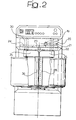
- the machine of figures 1 - 4 comprises a basement 10 and a column 11 from which a head 12 projects in a cantilever fashion, so as to hang over the basement.
- a support 14 carried by a rotatable shaft 15 having an axis 15a.
- the shaft 15 is driven in rotation by a transmission 16 driven by a motor 17.
- the transmission is shown diagrammatically, since it can be made according to various possible equivalent configurations, as easily understood.
- Motor 17 also drives a belt transmission 18 for rotating the shaft 19 supported by the head 12 which drives a vertical shaft 20 through an orthogonal gear 21.
- a gear 22 which drives rotation of a gear 24 mounted on a shaft 30 through an intermediate gear 23.
- shafts 20 and 30, which rotate in the same direction and are supported by the head 12, there are fixed horizontal arms 25 and 35 which on their turn extend into vertical arms 26 and 36.
- Arms 26 and 36 are received within the cylindrical bowl 40 which is removably connected to support plate 14 and has its central axis coincident with axis 15a of shaft 15. The action of the kneading arms 26 and 36 is better explained with reference to the diagrams of figures 3 and 4.
- the axes 20a and 30a of shafts 20 and 30 lie on a chord of the circle representing the cross-section of bowl 40.
- the length of the radial arms 25 and 35 is such that the kneading arms 26 and 36 define respective theoretical cylinders which are substantially tangent to each other at an area T1.
- the position of shafts 20 and 30 is chosen so that the theoretical cylinders defined by arms 26 and 36 are substantially tangent to the wall of the bowl 40, at areas respectively designated by T2 and T3.
- the transmission ratios between motor 17 and shafts 15 and 20 - 30 respectively are chosen so that the tangential speed of arms 26 and 36 is greater than the tangential speed of the side wall of the bowl 40.
- arms 26, 36 preferably have a polygonal section, which has a sharp edge, forming a cutting edge, at the area of the arm facing in the direction of movement and towards the outside of the circular path followed by the arm. In the embodiment shown, this edge is respectively designated by 27 and 37 for the two arms 26, 36.
- Actuation of motor 17 causes rotation both of the bowl 40 and the arms 26, 36. Even a slow rotation of the bowl, such as between 5 and 10 rounds per minute, ensures that the entire mass of dough introduced therein is affected by the action of the kneading arms 26, 36.
- the kneading arms rotate at a greater speed (such as 30 - 50 rounds per minute) and perform a generic kneading action on the mass of dough, imparting a strong cutting action thereon due to that the rotation of the two arms 26, 36 is synchronized so that these arms pass substantially simultaneously at the area where the respective theoretical cylinders are tangent to each other.
- each of the arms 26, 36 tends to move the dough in the direction opposite to that of the other arm, so that at the area T1 a substantially shear-like action is exerted, particularly with the aid of the cutting edges.
- the arms move away from each other due to their rotation causing thereby an "opening" of the mass so that the latter is extensively placed in contact with the air and is thus oxygenated and prevented from heating.
- each arm moves closer to the wall of the bowl with a tangential speed which is greater than the speed of the wall, so that the arm strongly penetrates in the mass held by the wall of the bowl 40, also due to the presence of the front cutting edge formed on the kneading arm.
- arms 26, 36 Since the path of arms 26, 36 is such that these arms come in close proximity to the wall, also a cleaning action on the wall is obtained, so that there are no areas in the bowl left where some material may remain or adhere so as to be not subjected to a mixing and kneading action. For this reason, it is preferable that the length of the arms is such that their free end comes in close proximity to the bottom of the bowl.
- the shape of the cross-section of the kneading arms may be varied, while preferably always providing a cutting edge which favours penetration of the arm into the mass, for performing a cutting action.
- the ratio between the diameter of the path of the kneading arms and the diameter of the bowl is not critical and depends from the distance between the chord on which the axes of rotation of the two kneading tools are located and the centre of the bowl. If this distance is lower than the radius of the theoretical cylinders defined by two arms, as in the illustrated embodiment, it is possible to obtain a satisfactory combination of the cutting action and the mixing action.
- the configuration of the machine and the apparatus for transmitting the movements can be chosen with a great freedom while adopting the essential features which form the subject of the following claims.
- the general configuration of the machine can also be completely different from that described above purely by way of example. It is possible for instance to provide a column 11 of telescopic type, in order to enable the head above the bowl to be raised for withdrawing arms 26, 36 from the bowl and allowing easy removal of the bowl itself in view of emptying the bowl from the material contained therein.
- the machine is provided with a single kneading tool of the above described type, which cooperates with a fixed cooperating member which projects downwardly from the head of the machine, within the rotating bowl.
- This fixed cooperating member may be formed by an arm arranged at a fixed position where the theoretical cylinder of the single kneading tool is tangent to a diametrical plane of the bowl. In this case, the cutting effect is due to the action of a single rotating arm and the cooperating fixed member.
- a further possible variant may consist in providing more than two kneading tools cooperating with each other.
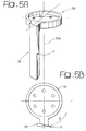
- Figure 5A shows a perspective view of a further embodiment of one of the two kneading tools of the machine of figures 1 - 4.
- the kneading tool shown in figure 5A, as well as in the plan view of figure 5B, designated by reference number 26, preferably has a cross-section in form of a right-angled trapezium (see figure 5B) so as to define a front edge, with reference to the direction of rotation (designated by arrow A in figure 5B) which is a cutting edge S able to cause a stretching action and subsequently a clear cut in the dough each time that it passes across the other kneading tool 36 of the machine (which naturally may have an identical configuration).
- the kneading tool 26 is constituted by a straight arm, parallel to any generatrix of the theoretical cylinder which is defined thereby in the rotation around axis 20a.
- the figures show a solution where the arm formed in the tool 26 extends from an upper disc 50, which is for coupling to the respective driving shaft.
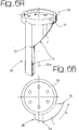
- Figures 6A, 6B show a variant of the kneading tool of figures 5A, 5B in which the arm 26 extends from the coupling disc 50 with a root portion r having a substantially triangular shape, with a width progressively decreasing downwardly from the coupling disc 50.
- the portion r has one edge whose ends are designated in figure 6A by S 1 , S 2 which lies on the surface of the theoretical cylinder defined by arm 26 and is strongly inclined with respect to a generatrix of this theoretical cylinder. Therefore, the edge S of the kneading tool has a greater extension with respect to the solution shown in figures 5A, 5B.
- the object of portion r is first of all that of increasing the cutting action due to the greater length of edge S.
- portion of the cutting edge S corresponding to that between S 1 and S 2 is arranged on the same theoretical cylinder on which the lower portion of edge S of arm 26 is arranged.
- a further advantage of the provision of portion r is that, due to the inclined arrangement of its edge, during the cutting action it pushes the cut dough downwardly avoiding thereby that the dough is twisted around the kneading tool and clines thereon.
- a further advantage of portion r is that of strengthening the arm 26 due to a great increase of its cross-section at the connecting area to disc 50.
- Figures 7A, 7B show a further a variant of the solution of figures 5A, 5B, in which arm 26 is again straight but arranged according to a direction which is slightly inclined with respect to a generatrix of the theoretical cylinder defined by the kneading tool in its rotation.
- angle ⁇ formed between arm 26 of the solution of figure 7A, 7B and any generatrix of the respective theoretical cylinder may be comprised between 0° and 10°.
- the solution shown relates specifically to a case in which angle ⁇ is 4.5°, which value has demonstrated to be particularly advantageous. However, other values may be adopted within the range of values which has been indicated. Angles much greater than 10° are not advisable since arm 26 is straight, whereby its opposite ends rotate on different orbital paths with respect to the axis of rotation of the tool.
- Figures 8A, 8B show a further variant which is a combination of the solution of figures 6A, 6B and 7A, 7B since it has an arm 26 inclined by an angle ⁇ with respect to a generatrix of the respective theoretical cylinder, as in the case of the solution shown in figures 7A, 7B, and is further provided with a root portion r, as in the case of the solution shown in figures 6A, 6B.
- the parts in common to those figures are designated by the same reference numbers.
- the arm 26 has a lower end portion q which has its front face (again with reference to the direction of rotation of the arm) which is parallel to any generatrix of the theoretical cylinder of the tool.
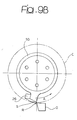
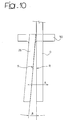
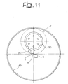
- Figures 9A, 9B, 10 and 11 relate to a further embodiment of invention which has a single kneading tool 26, shaped according to any of the variants provided in the embodiment which has been previously described for both the kneading tools.
- the kneading tool 26 is of the type shown in figures 7A, 7B. However, as indicated, it could have any of the configurations of figures 5, 6 and 8, or even a further alternative configuration.
- the single kneading tool 26 cooperates with a fixed cooperating member O which is supported at a fixed position within the bowl by the head 12 of the machine, which projects above the bowl.
- the fixed cooperating member O is in form of a substantially straight bar directed parallel to any generatrix of the theoretical cylinder C defined by the kneading tool, 26 in its rotation around axis 28.
- the cooperating member O is further arranged substantially tangent to this theoretical cylinder and preferably has a cross-section in form of a trapezium (figure 9B) substantially corresponding to that of kneading arm 26, defining a cutting edge R which cooperates with the cutting edge S of arm 26 each time that the arm passed across the cooperating member O in order to obtain the required cutting effect.
- the cooperating member O could also have a cutting edge R with an extension corresponding to that of the cutting edge S of arm 26 of the solution of figure 6.
- Figure 11 shows a plan view of the machine provided according to this second embodiment, where the cutting edge R of the fixed cooperating member O is arranged at the axis of the bowl. It is also visible that in this solution the theoretical cylinder C of the kneading tool has a diameter which is substantially identical to the inner radius of the bowl.
Landscapes
- Chemical & Material Sciences (AREA)
- Chemical Kinetics & Catalysis (AREA)
- Life Sciences & Earth Sciences (AREA)
- Engineering & Computer Science (AREA)
- Food Science & Technology (AREA)
- Manufacturing And Processing Devices For Dough (AREA)
- Food-Manufacturing Devices (AREA)
- Bakery Products And Manufacturing Methods Therefor (AREA)
- Mixers Of The Rotary Stirring Type (AREA)
- Noodles (AREA)
Priority Applications (2)
| Application Number | Priority Date | Filing Date | Title |
|---|---|---|---|
| EP05007223A EP1550499B1 (de) | 2002-03-05 | 2003-02-21 | Knetmaschine für Teigmittel, insbesondere für Backwaren |
| EP05007224A EP1550500B1 (de) | 2002-03-05 | 2003-02-21 | Knetverfahren und Knetmaschine für Teigmittel, insbesondere für Backwaren |
Applications Claiming Priority (4)
| Application Number | Priority Date | Filing Date | Title |
|---|---|---|---|
| IT2002MI000454A ITMI20020454A1 (it) | 2002-03-05 | 2002-03-05 | Macchina impastatrice per paste alimentari |
| ITMI20020454 | 2002-03-05 | ||
| ITTO20021020 | 2002-11-26 | ||
| IT001020A ITTO20021020A1 (it) | 2002-11-26 | 2002-11-26 | Macchina impastatrice per paste alimentari particolarmente |
Related Child Applications (2)
| Application Number | Title | Priority Date | Filing Date |
|---|---|---|---|
| EP05007224A Division EP1550500B1 (de) | 2002-03-05 | 2003-02-21 | Knetverfahren und Knetmaschine für Teigmittel, insbesondere für Backwaren |
| EP05007223A Division EP1550499B1 (de) | 2002-03-05 | 2003-02-21 | Knetmaschine für Teigmittel, insbesondere für Backwaren |
Publications (2)
| Publication Number | Publication Date |
|---|---|
| EP1342501A2 true EP1342501A2 (de) | 2003-09-10 |
| EP1342501A3 EP1342501A3 (de) | 2003-11-19 |
Family
ID=27758892
Family Applications (3)
| Application Number | Title | Priority Date | Filing Date |
|---|---|---|---|
| EP05007224A Expired - Lifetime EP1550500B1 (de) | 2002-03-05 | 2003-02-21 | Knetverfahren und Knetmaschine für Teigmittel, insbesondere für Backwaren |
| EP03003912A Withdrawn EP1342501A3 (de) | 2002-03-05 | 2003-02-21 | Knetmaschine für Teigmittel, insbesondere für Backwaren |
| EP05007223A Expired - Lifetime EP1550499B1 (de) | 2002-03-05 | 2003-02-21 | Knetmaschine für Teigmittel, insbesondere für Backwaren |
Family Applications Before (1)
| Application Number | Title | Priority Date | Filing Date |
|---|---|---|---|
| EP05007224A Expired - Lifetime EP1550500B1 (de) | 2002-03-05 | 2003-02-21 | Knetverfahren und Knetmaschine für Teigmittel, insbesondere für Backwaren |
Family Applications After (1)
| Application Number | Title | Priority Date | Filing Date |
|---|---|---|---|
| EP05007223A Expired - Lifetime EP1550499B1 (de) | 2002-03-05 | 2003-02-21 | Knetmaschine für Teigmittel, insbesondere für Backwaren |
Country Status (6)
| Country | Link |
|---|---|
| US (1) | US7073934B2 (de) |
| EP (3) | EP1550500B1 (de) |
| JP (1) | JP2004033213A (de) |
| AT (2) | ATE367197T1 (de) |
| DE (2) | DE60315052T2 (de) |
| ES (1) | ES2270397T3 (de) |
Cited By (10)
| Publication number | Priority date | Publication date | Assignee | Title |
|---|---|---|---|---|
| EP1527688A3 (de) * | 2003-11-03 | 2005-11-23 | SANCASSIANO S.p.A. | Horizontale Knetmaschine für essbaren Teig, insbesondere für im Ofen gebackene Produkten |
| US7073934B2 (en) * | 2002-03-05 | 2006-07-11 | Sancassiano | Kneading machine for food doughs, particularly for bakery products |
| EP1707052A3 (de) * | 2005-03-29 | 2007-06-20 | SANCASSIANO S.p.A. | Knetmaschine für Teigmittel |
| EP1969943A1 (de) * | 2007-03-16 | 2008-09-17 | SANCASSIANO S.p.A. | Knetmaschine für Lebensmittel |
| CN101711958A (zh) * | 2008-09-26 | 2010-05-26 | 赫费尔德两合公司 | 搅拌机 |
| CN103202324A (zh) * | 2013-02-05 | 2013-07-17 | 惠阳亚伦塑胶电器实业有限公司 | 一种食品搓揉设备 |
| CN108176301A (zh) * | 2018-03-08 | 2018-06-19 | 陕西杨凌陕特农业发展有限公司 | 一种蜂蜜搅拌装置 |
| CN109012380A (zh) * | 2018-06-30 | 2018-12-18 | 湖州博润实业有限公司 | 一种搅拌效果好的染色布用染料搅拌装置 |
| CN109277022A (zh) * | 2018-12-01 | 2019-01-29 | 江苏振达环保科技有限公司 | 一种污水处理罐用高效搅拌装置 |
| CN112169681A (zh) * | 2020-09-28 | 2021-01-05 | 重庆文理学院 | 一种猕猴桃抗病害用药液肥料混合装置 |
Families Citing this family (9)
| Publication number | Priority date | Publication date | Assignee | Title |
|---|---|---|---|---|
| ITTO20021020A1 (it) * | 2002-11-26 | 2004-05-27 | Sancassiano Spa | Macchina impastatrice per paste alimentari particolarmente |
| US8739696B2 (en) | 2008-10-23 | 2014-06-03 | Insitu Foods, Inc. | Dough preparing machine |
| US9295264B2 (en) * | 2012-01-06 | 2016-03-29 | Anderson Group, Ltd. | Dough preparing machine with dough dividing in bowl |
| CN104161067B (zh) * | 2014-09-10 | 2016-02-03 | 北大荒丰缘集团有限公司 | 带预混箱的和面机机箱 |
| CN109757537A (zh) * | 2017-11-09 | 2019-05-17 | 广东牧人王电器有限公司 | 一种环保静音液压动力揉面机 |
| CN108607434A (zh) * | 2018-05-22 | 2018-10-02 | 马鞍山纽泽科技服务有限公司 | 一种化工原料搅拌装置 |
| CN111167349A (zh) * | 2020-02-28 | 2020-05-19 | 温州阳格凡电子科技有限公司 | 一种化工搅拌机 |
| CN111939795A (zh) * | 2020-08-03 | 2020-11-17 | 马鞍山科邦生态肥有限公司 | 一种具有防堵塞功能的有机生物肥原料混合装置 |
| CN115069125B (zh) * | 2022-08-11 | 2022-10-25 | 汕头市光彩新材料科技有限公司 | 环保型uv油墨防迁移助剂同轴异向自卸式搅拌混合装置 |
Family Cites Families (20)
| Publication number | Priority date | Publication date | Assignee | Title |
|---|---|---|---|---|
| NL26485C (de) * | 1900-01-01 | |||
| US158365A (en) * | 1875-01-05 | Improvement in churns | ||
| US131877A (en) * | 1872-10-01 | Improvement in churns | ||
| US376625A (en) * | 1888-01-17 | Churn | ||
| US244226A (en) * | 1881-07-12 | Churn | ||
| US293A (en) * | 1837-07-22 | Mode of | ||
| US2115742A (en) * | 1936-09-10 | 1938-05-03 | Roger H Newton | Mixing |
| GB659240A (en) * | 1949-06-16 | 1951-10-17 | Andre Constant Simon | Improvements in or relating to apparatus for mixing or working materials, particularly pastes, especially chocolate pastes |
| DE842182C (de) * | 1950-07-11 | 1952-06-23 | Haagen & Rinau Maschinenfabrik | Misch- und Knetmaschine mit drehbar gelagertem Trog und ebenfalls drehbar gelagertem Kneter |
| FR1226289A (fr) * | 1958-06-04 | 1960-07-11 | Bayer Ag | Récipient à agitateur pour la conduite continue de réactions fortement exothermiques dans des milieux visqueux ou même dans des milieux pâteux peu consistants |
| BE790907A (fr) * | 1971-11-04 | 1973-03-01 | Golden Vale Food Products Ltd | Cuve a fromage |
| ES292402Y (es) * | 1986-02-20 | 1987-02-16 | Suay Puig Enrique | Amasadora para la fabricacion de pan con extraccion automatica de la masa |
| IT206942Z2 (it) * | 1986-06-25 | 1987-10-19 | Sancassiano Spa | Macchina impastatrice particolarmente per impasti di prodotti alimentari |
| IT215075Z2 (it) * | 1988-07-05 | 1990-07-30 | Sancassiano Spa | Macchina impastatrice particolarmente per prodotti alimentari |
| JP3112809B2 (ja) * | 1995-05-22 | 2000-11-27 | ハウス食品株式会社 | 混合攪拌装置 |
| US5906432A (en) * | 1997-09-19 | 1999-05-25 | American Ingredients Company | Dough mixer apparatus for laboratory testing of the development of a dough sample |
| US6652137B1 (en) * | 2000-03-16 | 2003-11-25 | Charles Ross & Son Company | Stirrer for a planetary mixer and a planetary mixer incorporating the stirrer |
| ATE367197T1 (de) * | 2002-03-05 | 2007-08-15 | Sancassiano Spa | Knetverfahren und knetmaschine für teigmittel, insbesondere für backwaren |
| ITTO20021020A1 (it) * | 2002-11-26 | 2004-05-27 | Sancassiano Spa | Macchina impastatrice per paste alimentari particolarmente |
| ITTO20030863A1 (it) * | 2003-11-03 | 2005-05-04 | Sancassiano Spa | Macchina impastatrice orizzontale per paste alimentari, particolarmente per prodotti da forno. |
-
2003
- 2003-02-21 AT AT05007224T patent/ATE367197T1/de not_active IP Right Cessation
- 2003-02-21 EP EP05007224A patent/EP1550500B1/de not_active Expired - Lifetime
- 2003-02-21 DE DE60315052T patent/DE60315052T2/de not_active Expired - Lifetime
- 2003-02-21 EP EP03003912A patent/EP1342501A3/de not_active Withdrawn
- 2003-02-21 ES ES05007223T patent/ES2270397T3/es not_active Expired - Lifetime
- 2003-02-21 EP EP05007223A patent/EP1550499B1/de not_active Expired - Lifetime
- 2003-02-21 AT AT05007223T patent/ATE335534T1/de not_active IP Right Cessation
- 2003-02-21 DE DE60307493T patent/DE60307493T2/de not_active Expired - Lifetime
- 2003-03-04 US US10/377,736 patent/US7073934B2/en not_active Expired - Lifetime
- 2003-03-04 JP JP2003057410A patent/JP2004033213A/ja active Pending
Cited By (12)
| Publication number | Priority date | Publication date | Assignee | Title |
|---|---|---|---|---|
| US7073934B2 (en) * | 2002-03-05 | 2006-07-11 | Sancassiano | Kneading machine for food doughs, particularly for bakery products |
| EP1527688A3 (de) * | 2003-11-03 | 2005-11-23 | SANCASSIANO S.p.A. | Horizontale Knetmaschine für essbaren Teig, insbesondere für im Ofen gebackene Produkten |
| EP1707052A3 (de) * | 2005-03-29 | 2007-06-20 | SANCASSIANO S.p.A. | Knetmaschine für Teigmittel |
| EP1969943A1 (de) * | 2007-03-16 | 2008-09-17 | SANCASSIANO S.p.A. | Knetmaschine für Lebensmittel |
| CN101711958A (zh) * | 2008-09-26 | 2010-05-26 | 赫费尔德两合公司 | 搅拌机 |
| CN101711958B (zh) * | 2008-09-26 | 2014-05-07 | 赫费尔德两合公司 | 搅拌机 |
| CN103202324A (zh) * | 2013-02-05 | 2013-07-17 | 惠阳亚伦塑胶电器实业有限公司 | 一种食品搓揉设备 |
| CN103202324B (zh) * | 2013-02-05 | 2015-04-15 | 惠阳亚伦塑胶电器实业有限公司 | 一种食品搓揉设备 |
| CN108176301A (zh) * | 2018-03-08 | 2018-06-19 | 陕西杨凌陕特农业发展有限公司 | 一种蜂蜜搅拌装置 |
| CN109012380A (zh) * | 2018-06-30 | 2018-12-18 | 湖州博润实业有限公司 | 一种搅拌效果好的染色布用染料搅拌装置 |
| CN109277022A (zh) * | 2018-12-01 | 2019-01-29 | 江苏振达环保科技有限公司 | 一种污水处理罐用高效搅拌装置 |
| CN112169681A (zh) * | 2020-09-28 | 2021-01-05 | 重庆文理学院 | 一种猕猴桃抗病害用药液肥料混合装置 |
Also Published As
| Publication number | Publication date |
|---|---|
| EP1550499A3 (de) | 2005-12-14 |
| DE60307493T2 (de) | 2007-09-13 |
| EP1550499A2 (de) | 2005-07-06 |
| EP1550500B1 (de) | 2007-07-18 |
| DE60315052D1 (de) | 2007-08-30 |
| JP2004033213A (ja) | 2004-02-05 |
| ATE367197T1 (de) | 2007-08-15 |
| US20030167931A1 (en) | 2003-09-11 |
| EP1550500A3 (de) | 2005-12-14 |
| EP1550499B1 (de) | 2006-08-09 |
| DE60307493D1 (de) | 2006-09-21 |
| ES2270397T3 (es) | 2007-04-01 |
| EP1342501A3 (de) | 2003-11-19 |
| ATE335534T1 (de) | 2006-09-15 |
| US7073934B2 (en) | 2006-07-11 |
| EP1550500A2 (de) | 2005-07-06 |
| DE60315052T2 (de) | 2008-04-03 |
Similar Documents
| Publication | Publication Date | Title |
|---|---|---|
| EP1550499B1 (de) | Knetmaschine für Teigmittel, insbesondere für Backwaren | |
| US6997597B2 (en) | Kneading machine for food doughs, particularly for bakery products | |
| EP3422917B1 (de) | Schraubenförmiges schlägerelement und schlägersystem | |
| US6955110B1 (en) | Apparatus and method for cutting soft materials, especially meat | |
| WO2002068122A1 (en) | Apparatus for and method of shredding a product | |
| KR101498602B1 (ko) | 누들 절단 장치 및 방법 | |
| US5791779A (en) | Mixing assembly for continuous mixer | |
| GB2186810A (en) | A kneader | |
| EP0354190A1 (de) | Knetmaschine für Nahrungsprodukte, insbesondere Mehlgemische | |
| KR20110016482A (ko) | 재료를 반죽 덩어리로 반죽하기 위한 반죽 장치 및 반죽 공구 | |
| JPH02258309A (ja) | 加硫されてないゴムを再加工する装置 | |
| RU2543458C2 (ru) | Мешалка для электрического кухонного прибора | |
| US20070199423A1 (en) | Apparatus and method for ultrasonic cutting | |
| EP3089591B1 (de) | Rotor für teigknetmaschinen für lebensmittel und teigknetmaschine | |
| EP1707052A2 (de) | Knetmaschine für Teigmittel | |
| EP2377600A2 (de) | Klingenanordnung für einen Lebensmittelverarbeitungsbottich | |
| US4111112A (en) | Fruit sectionizing machine | |
| EP0611264A1 (de) | Schleuderscheibe für Schleuderdüngerstreuer und Düngerstreuer mit dieser Scheibe | |
| KR100435348B1 (ko) | 반죽 상에 주름을 성형하는 방법 및 장치 | |
| JP5954824B2 (ja) | 製麺用切刃ロール | |
| EP0042681A2 (de) | Mischwerkzeug für eine Haushalts-Mischmaschine | |
| JP3059154B1 (ja) | 表皮削り取り装置 | |
| CN108338706A (zh) | 一种食物料理器 | |
| CN222997779U (zh) | 弯刃旋转刀组 | |
| RU2560623C2 (ru) | Устройство для разматывания массы спутанной лапши |
Legal Events
| Date | Code | Title | Description |
|---|---|---|---|
| PUAI | Public reference made under article 153(3) epc to a published international application that has entered the european phase |
Free format text: ORIGINAL CODE: 0009012 |
|
| AK | Designated contracting states |
Kind code of ref document: A2 Designated state(s): AT BE BG CH CY CZ DE DK EE ES FI FR GB GR HU IE IT LI LU MC NL PT SE SI SK TR |
|
| AX | Request for extension of the european patent |
Extension state: AL LT LV MK RO |
|
| PUAL | Search report despatched |
Free format text: ORIGINAL CODE: 0009013 |
|
| AK | Designated contracting states |
Kind code of ref document: A3 Designated state(s): AT BE BG CH CY CZ DE DK EE ES FI FR GB GR HU IE IT LI LU MC NL PT SE SI SK TR |
|
| AX | Request for extension of the european patent |
Extension state: AL LT LV MK RO |
|
| 17P | Request for examination filed |
Effective date: 20040105 |
|
| 17Q | First examination report despatched |
Effective date: 20040303 |
|
| AKX | Designation fees paid |
Designated state(s): AT BE BG CH CY CZ DE DK EE ES FI FR GB GR HU IE IT LI LU MC NL PT SE SI SK TR |
|
| STAA | Information on the status of an ep patent application or granted ep patent |
Free format text: STATUS: THE APPLICATION IS DEEMED TO BE WITHDRAWN |
|
| 18D | Application deemed to be withdrawn |
Effective date: 20050819 |