EP1342875A1 - Charnière avec un élément de rappel pour fermer automatiquement une porte - Google Patents
Charnière avec un élément de rappel pour fermer automatiquement une porte Download PDFInfo
- Publication number
- EP1342875A1 EP1342875A1 EP02251632A EP02251632A EP1342875A1 EP 1342875 A1 EP1342875 A1 EP 1342875A1 EP 02251632 A EP02251632 A EP 02251632A EP 02251632 A EP02251632 A EP 02251632A EP 1342875 A1 EP1342875 A1 EP 1342875A1
- Authority
- EP
- European Patent Office
- Prior art keywords
- rotatable
- cam element
- hinge member
- cam
- hinge
- Prior art date
- Legal status (The legal status is an assumption and is not a legal conclusion. Google has not performed a legal analysis and makes no representation as to the accuracy of the status listed.)
- Withdrawn
Links
Images


Classifications
-
- E—FIXED CONSTRUCTIONS
- E05—LOCKS; KEYS; WINDOW OR DOOR FITTINGS; SAFES
- E05F—DEVICES FOR MOVING WINGS INTO OPEN OR CLOSED POSITION; CHECKS FOR WINGS; WING FITTINGS NOT OTHERWISE PROVIDED FOR, CONCERNED WITH THE FUNCTIONING OF THE WING
- E05F1/00—Closers or openers for wings, not otherwise provided for in this subclass
- E05F1/08—Closers or openers for wings, not otherwise provided for in this subclass spring-actuated, e.g. for horizontally sliding wings
- E05F1/10—Closers or openers for wings, not otherwise provided for in this subclass spring-actuated, e.g. for horizontally sliding wings for swinging wings, e.g. counterbalance
- E05F1/12—Mechanisms in the shape of hinges or pivots, operated by springs
- E05F1/1207—Mechanisms in the shape of hinges or pivots, operated by springs with a coil spring parallel with the pivot axis
- E05F1/1223—Mechanisms in the shape of hinges or pivots, operated by springs with a coil spring parallel with the pivot axis with a compression or traction spring
-
- E—FIXED CONSTRUCTIONS
- E05—LOCKS; KEYS; WINDOW OR DOOR FITTINGS; SAFES
- E05D—HINGES OR SUSPENSION DEVICES FOR DOORS, WINDOWS OR WINGS
- E05D11/00—Additional features or accessories of hinges
- E05D11/08—Friction devices between relatively-movable hinge parts
-
- E—FIXED CONSTRUCTIONS
- E05—LOCKS; KEYS; WINDOW OR DOOR FITTINGS; SAFES
- E05D—HINGES OR SUSPENSION DEVICES FOR DOORS, WINDOWS OR WINGS
- E05D3/00—Hinges with pins
- E05D3/02—Hinges with pins with one pin
- E05D2003/025—Hinges with pins with one pin having three knuckles
- E05D2003/027—Hinges with pins with one pin having three knuckles the end knuckles being mutually connected
-
- E—FIXED CONSTRUCTIONS
- E05—LOCKS; KEYS; WINDOW OR DOOR FITTINGS; SAFES
- E05F—DEVICES FOR MOVING WINGS INTO OPEN OR CLOSED POSITION; CHECKS FOR WINGS; WING FITTINGS NOT OTHERWISE PROVIDED FOR, CONCERNED WITH THE FUNCTIONING OF THE WING
- E05F1/00—Closers or openers for wings, not otherwise provided for in this subclass
- E05F1/02—Closers or openers for wings, not otherwise provided for in this subclass gravity-actuated, e.g. by use of counterweights
- E05F1/04—Closers or openers for wings, not otherwise provided for in this subclass gravity-actuated, e.g. by use of counterweights for wings which lift during movement, operated by their own weight
- E05F1/06—Mechanisms in the shape of hinges or pivots, operated by the weight of the wing
- E05F1/061—Mechanisms in the shape of hinges or pivots, operated by the weight of the wing with cams or helical tracks
- E05F1/063—Mechanisms in the shape of hinges or pivots, operated by the weight of the wing with cams or helical tracks with complementary, substantially identical and slidingly cooperating cam surfaces
-
- E—FIXED CONSTRUCTIONS
- E05—LOCKS; KEYS; WINDOW OR DOOR FITTINGS; SAFES
- E05F—DEVICES FOR MOVING WINGS INTO OPEN OR CLOSED POSITION; CHECKS FOR WINGS; WING FITTINGS NOT OTHERWISE PROVIDED FOR, CONCERNED WITH THE FUNCTIONING OF THE WING
- E05F1/00—Closers or openers for wings, not otherwise provided for in this subclass
- E05F1/08—Closers or openers for wings, not otherwise provided for in this subclass spring-actuated, e.g. for horizontally sliding wings
- E05F1/10—Closers or openers for wings, not otherwise provided for in this subclass spring-actuated, e.g. for horizontally sliding wings for swinging wings, e.g. counterbalance
- E05F1/12—Mechanisms in the shape of hinges or pivots, operated by springs
- E05F1/1292—Mechanisms in the shape of hinges or pivots, operated by springs with a gas spring
-
- E—FIXED CONSTRUCTIONS
- E05—LOCKS; KEYS; WINDOW OR DOOR FITTINGS; SAFES
- E05F—DEVICES FOR MOVING WINGS INTO OPEN OR CLOSED POSITION; CHECKS FOR WINGS; WING FITTINGS NOT OTHERWISE PROVIDED FOR, CONCERNED WITH THE FUNCTIONING OF THE WING
- E05F3/00—Closers or openers with braking devices, e.g. checks; Construction of pneumatic or liquid braking devices
- E05F3/20—Closers or openers with braking devices, e.g. checks; Construction of pneumatic or liquid braking devices in hinges
-
- E—FIXED CONSTRUCTIONS
- E05—LOCKS; KEYS; WINDOW OR DOOR FITTINGS; SAFES
- E05Y—INDEXING SCHEME ASSOCIATED WITH SUBCLASSES E05D AND E05F, RELATING TO CONSTRUCTION ELEMENTS, ELECTRIC CONTROL, POWER SUPPLY, POWER SIGNAL OR TRANSMISSION, USER INTERFACES, MOUNTING OR COUPLING, DETAILS, ACCESSORIES, AUXILIARY OPERATIONS NOT OTHERWISE PROVIDED FOR, APPLICATION THEREOF
- E05Y2201/00—Constructional elements; Accessories therefor
- E05Y2201/60—Suspension or transmission members; Accessories therefor
- E05Y2201/622—Suspension or transmission members elements
- E05Y2201/638—Cams; Ramps
-
- E—FIXED CONSTRUCTIONS
- E05—LOCKS; KEYS; WINDOW OR DOOR FITTINGS; SAFES
- E05Y—INDEXING SCHEME ASSOCIATED WITH SUBCLASSES E05D AND E05F, RELATING TO CONSTRUCTION ELEMENTS, ELECTRIC CONTROL, POWER SUPPLY, POWER SIGNAL OR TRANSMISSION, USER INTERFACES, MOUNTING OR COUPLING, DETAILS, ACCESSORIES, AUXILIARY OPERATIONS NOT OTHERWISE PROVIDED FOR, APPLICATION THEREOF
- E05Y2900/00—Application of doors, windows, wings or fittings thereof
- E05Y2900/10—Application of doors, windows, wings or fittings thereof for buildings or parts thereof
- E05Y2900/13—Type of wing
- E05Y2900/132—Doors
Definitions
- a hinge device of the present invention includes a stationary hinge member, a rotatable hinge member, a cam mechanism, and a biasing member.
- the rotatable hinge member is pivoted to the stationary hinge member so as to rotate about a vertical axis between open and closed positions.
- the cam mechanism includes a rotatable cam element that is coupled to the rotatable hinge member so as to rotate about the vertical axis together with the rotatable hinge member and that is formed with a first cam face, and a slidable cam element that is formed with a second cam face associated with the first cam face and that is movable in an axial direction along the vertical axis.
- the rotatable hinge member 3 is pivoted to the stationary hinge member 4 so as to rotate about a vertical axis between open and closed positions, as best shown in Figures 2 and 3, respectively.
- the cam mechanism includes a rotatable cam element 66 that is coupled to the rotatable hinge member 3 so as to rotate about the vertical axis together with the rotatable hinge member 3 and that is formed with a first cam face 665, and a slidable cam element 77 that is formed with a second cam face 775 associated with the first cam face 665 and that is movable in an axial direction along the vertical axis.
- a rotatable cam element 66 that is coupled to the rotatable hinge member 3 so as to rotate about the vertical axis together with the rotatable hinge member 3 and that is formed with a first cam face 665
- a slidable cam element 77 that is formed with a second cam face 775 associated with the first cam face 665 and that is movable in an axial direction along the vertical axis.
- the biasing member 75 such a compression spring, is connected to the slidable cam element 77 in such a manner so as to accumulate a returning force when the second cam face 775 moves away from the first cam face 665 and so as to urge the second cam face 775 toward the first cam face 665 when the external force ceases to be applied on the rotatable hinge member 3, thereby returning the rotatable hinge member 3 from the open position to the closed position.
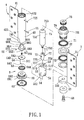
- the stationary hinge member 4 preferably includes a stationary leaf 41 adapted to be mounted on a door frame (not shown) , and a hollow tubular member 42 fixed to the stationary leaf 41 and within which the rotatable cam element 66 and the slidable cam element 77 are received one above the other.
- the rotatable cam element 66 includes a cylindrical portion 661 that extends in the axial direction, and that has a top end defining a top abutment face 668.
- the top abutment face 668 extends in a transverse direction relative to the vertical axis.
- the cylindrical portion 661 is further formed with two opposing V-shaped notches 666 which extend inclinedly and downwardly from the top abutment face 668 and which cooperatively define the first cam face 665.
- the slidable cam element 77 includes a cylindrical portion 771 that extends in the axial direction, and that is disposed above the cylindrical portion 661 of the rotatable cam element 66.
- the cylindrical portion 771 has a bottom abutment face 778 extending in the transverse direction.
- the cylindrical portion 771 of the slidable cam element 77 is formed with two opposing V-shaped notches 777 which extend inclinedly and upwardly from the bottom abutment face 778 and which cooperatively define the second cam face 775.
- top and bottom abutment faces 668,778 of the rotatable and slidable cam elements 66, 77 abut and push against each other by the returning force of the biasing member 75 when the rotatable hinge member 3 rotates from the open position to a stationary position, thereby permitting positioning of the rotatable hinge member 3 stationarily relative to the stationary hinge member 4.
- a guide tube 51 is mounted securely within the tubular member 42 via a fastener pin 55 to define an element-receiving chamber 510, within which the rotatable and slidable cam elements 66, 77 are received.
- the guide tube 51 has a top end 511, and is formed with two opposing guide grooves 53 that extend from the top end 511 and that communicate with the element-receiving chamber 510.
- the cylindrical portion 771 of the slidable cam element 77 has two radially and outwardly extending guide studs 73 that respectively project into the guide grooves 53 so as to ensure sliding movement of the slidable cam element 66 in the axial direction.
- a rotatable connecting member 64 is disposed in the tubular member 42 below the rotatable cam element 66, and includes a cylindrical piece 641 that has top and bottom ends, and a top annular flange 643 projecting radially and outwardly from the top end of the cylindrical piece 64 and abutting against a bottom end of the cylindrical portion 661 of the rotatable cam element 66.
- the cylindrical piece 641 is formed with a non-circular spring-mounting recess 645 that extends inwardly from the top end of the cylindrical piece 641 in the axial direction.
- An urging member 65 such as a biasing spring, is mounted in the spring-mounting recess 645.
- the rotatable cam element 66 further includes a non-circular reduced portion 662 that projects axially from the bottom end of the cylindrical portion 661 and into the spring-mounting recess 645 to engage the same so as to permit co-rotation of the connecting member 64 with the rotatable cam element 66, and to abut against the urging member 65 so as to provide a buffering action for counteracting the returning force of the biasing member 75 when the rotatable hinge member 3 is moved from the open position to the closed position. Under this condition, banging of the door relative to the door frame can be avoided during the door closing operation.
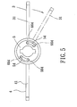
- the guide tube 51 has a bottom end 512, and is further formed with two opposing arcuate restricting slots 54 that extend from the bottom end 512 in the axial direction.
- the rotatable cam element 66 further includes an annular flange 663 that extends radially and outwardly from the bottom end of the cylindrical portion 661 and that is exposed from the bottom end 512 of the guide tube 51, and a pair of opposing restricting studs 664 that project from the annular flange 663 toward the bottom end 512 of the guide tube 51 in such a manner that the restricting studs 664 are offset from the restricting slots 54 when the rotatable hinge member 3 is disposed at the closed position and that the restricting studs 664 are respectively aligned with and are urged by the urging member 65 to extend into the restricting slots 54 when the rotatable hinge member 3 is disposed at either of the open and stationary positions.
- the rotatable hinge member 3 includes a rotatable leaf 31 adapted to be fixed on the door, and vertically spaced apart annular upper and lower couplers 32, 33 that are fixed to the rotatable leaf 31 and that sandwich the tubular member 42 of the stationary hinge member 4 therebetween.
- the lower coupler 33 is formed with a non-circular mounting hole 331.
- the bottom end 642 of the cylindrical piece 641 is formed with an inner threaded hole 644 that is in spatial communication with the non-circular spring-mounting recess 645.
- the bottom end 642 of the cylindrical piece 641 is non-circular in cross section, and extends into and engages the mounting hole 331 of the lower coupler 33 so as to permit co-rotation of the rotatable hinge member 3 and the rotatable cam element 66 via the rotatable connecting member 64.
- a screw bolt 68 is inserted threadedly from an exterior of the lower coupler 33 to engage the inner threaded hole 644 of the cylindrical piece 641 so as to retain the bottom end 642 of the cylindrical piece 641 in the mounting hole 331 of the lower coupler 33.
- the tubular member 42 in this embodiment has top and bottom inner threaded ends 422, 423.
- a pair of upper bearing units 71, 72 sandwich opposite sides of the upper coupler 32.
- a pair of lower bearing units 62, 63 is disposed in the tubular member 42 between the top annular flange 643 of the rotatable connecting member 64 and the lower coupler 33.
- the urging member 65 abuts against the reduced portion 662 of the rotatable cam element 66 and the screw bolt 68 in such a manner that tightening and loosening of the screw bolt 68 relative to the cylindrical piece 641 results in adjustment of the buffering action for counteracting the returning force of the biasing member 75.
- An upper bearing-positioning member 79 in the form of a hollow tube, is mounted threadedly on the top inner threaded end 422 of the tubular member 42, and has a radially and outwardly extending bearing-retention flange 791.
- the upper bearing units 71,72 are sleeved around the upper bearing-positioning member 79 in such a manner that the bearing-retention flange 791 cooperates with the upper coupler 32 to sandwich one of the upper bearing units 71 therebetween, and that the top inner threaded end 422 of the tubular member 42 cooperates with the upper coupler 32 to sandwich the other one of the upper bearing units 72 therebetween.
- the biasing member 75 includes a hydraulic cylinder 751 mounted securely in the tubular member 42 via a fastener pin 755, and extending into the upper bearing-positioning member 79 so as to enhance positioning of the hydraulic cylinder 751 in the tubular member 42.
- the hydraulic cylinder 751 has a piston 752 secured to a top end of the slidable cam element 77 so as to be movable in the axial direction for permitting accumulation of the returning force and restoration of the rotatable hinge member 3 to the closed position from the open position, and an adjustable knob 753 that projects from one end of the hydraulic cylinder 751 which is opposite to the piston 752 and that is movable inward and outward of the hydraulic cylinder 751 for adjusting an inner pressure inside the hydraulic cylinder 751.
Landscapes
- Hinges (AREA)
- Closing And Opening Devices For Wings, And Checks For Wings (AREA)
Priority Applications (3)
| Application Number | Priority Date | Filing Date | Title |
|---|---|---|---|
| EP02251632A EP1342875A1 (fr) | 2002-03-07 | 2002-03-07 | Charnière avec un élément de rappel pour fermer automatiquement une porte |
| JP2002076146A JP2003278431A (ja) | 2002-03-07 | 2002-03-19 | 自動閉扉蝶番 |
| US10/104,231 US6658694B2 (en) | 2002-03-07 | 2002-03-22 | Hinge device with a returning member for automatically closing an open door |
Applications Claiming Priority (3)
| Application Number | Priority Date | Filing Date | Title |
|---|---|---|---|
| EP02251632A EP1342875A1 (fr) | 2002-03-07 | 2002-03-07 | Charnière avec un élément de rappel pour fermer automatiquement une porte |
| JP2002076146A JP2003278431A (ja) | 2002-03-07 | 2002-03-19 | 自動閉扉蝶番 |
| US10/104,231 US6658694B2 (en) | 2002-03-07 | 2002-03-22 | Hinge device with a returning member for automatically closing an open door |
Publications (1)
| Publication Number | Publication Date |
|---|---|
| EP1342875A1 true EP1342875A1 (fr) | 2003-09-10 |
Family
ID=29721009
Family Applications (1)
| Application Number | Title | Priority Date | Filing Date |
|---|---|---|---|
| EP02251632A Withdrawn EP1342875A1 (fr) | 2002-03-07 | 2002-03-07 | Charnière avec un élément de rappel pour fermer automatiquement une porte |
Country Status (3)
| Country | Link |
|---|---|
| US (1) | US6658694B2 (fr) |
| EP (1) | EP1342875A1 (fr) |
| JP (1) | JP2003278431A (fr) |
Cited By (3)
| Publication number | Priority date | Publication date | Assignee | Title |
|---|---|---|---|---|
| WO2011012118A1 (fr) * | 2009-07-30 | 2011-02-03 | Zimmer Guenther | Charnière dotée d'un dispositif amortisseur hydraulique |
| US20130081228A1 (en) * | 2011-09-30 | 2013-04-04 | Itt Manufacturing Enterprises, Inc. | Rotary hinge with adjustable damping assembly |
| CN110307248A (zh) * | 2019-08-02 | 2019-10-08 | 东莞市宏联电子有限公司 | 铰链装置及无人机遥控器 |
Families Citing this family (35)
| Publication number | Priority date | Publication date | Assignee | Title |
|---|---|---|---|---|
| US7243394B2 (en) * | 2005-02-22 | 2007-07-17 | Ching Chih Kao | Door closing hinge device |
| AT502487B1 (de) * | 2005-10-06 | 2007-04-15 | Blum Gmbh Julius | Dämpferanordnung |
| KR100761904B1 (ko) * | 2006-08-08 | 2007-09-28 | 주식회사 아이원이노텍 | 건자재용 도어의 자동복귀 힌지장치 |
| US7779508B2 (en) * | 2006-10-02 | 2010-08-24 | Hardesty Bryan A | Refrigerator door closer and method |
| US20080136297A1 (en) * | 2006-10-05 | 2008-06-12 | Shan-Ping Huang | Hinge with buffer function |
| JP4934534B2 (ja) * | 2007-07-26 | 2012-05-16 | 三洋電機株式会社 | 貯蔵庫 |
| DE102007036747A1 (de) * | 2007-08-03 | 2009-02-05 | Dorma Gmbh + Co. Kg | Automatisierung von Möbeln, Haushaltsgeräten und dergleichen |
| KR101530737B1 (ko) * | 2007-11-27 | 2015-06-22 | 가부시키 가이샤 사와 | 자동도어 폐쇄 힌지 및 양쪽개방 도어 구조 |
| JP4651684B2 (ja) * | 2008-02-05 | 2011-03-16 | 株式会社サワ | 両開用自動閉扉蝶番及び両開扉構造 |
| US8182055B2 (en) * | 2008-04-22 | 2012-05-22 | Samsung Electronics Co., Ltd. | Damping unit and refrigerator having the same |
| IT1395306B1 (it) * | 2009-08-06 | 2012-09-05 | Gosio Dianora | Una cerniera per celle frigorifere, cancelli pedonali o similari |
| US8307503B1 (en) * | 2009-10-02 | 2012-11-13 | George Burger | Slow closing hinge apparatus |
| US20110302743A1 (en) * | 2009-11-25 | 2011-12-15 | Hyeon-Jung Kim | Hinge apparatus for a door |
| WO2012137042A1 (fr) * | 2011-04-05 | 2012-10-11 | In & Tec S.R.L. | Dispositif de charnière pour portes, volets ou analogues |
| DE102011007400A1 (de) * | 2011-04-14 | 2012-10-18 | Suspa Gmbh | Schließ-Scharnier |
| WO2012150481A1 (fr) * | 2011-05-04 | 2012-11-08 | Ol.Mi S.R.L. | Charnière |
| ITVR20130127A1 (it) * | 2013-05-27 | 2014-11-28 | Ind Casearia Silvio Belladell I S R L | Sistema a cerniere |
| ITVI20130245A1 (it) * | 2013-10-04 | 2015-04-05 | In & Tec Srl | Dispositivo a cerniera per porte, ante o similari |
| US20150345203A1 (en) * | 2014-05-28 | 2015-12-03 | Nuova Star S.P.A. | Hinge for doors of electrical household appliances |
| DE102014215902A1 (de) * | 2014-08-11 | 2016-02-11 | Suspa Gmbh | Dämpfungs-Scharnier zum Dämpfen einer Scharnier-Drehbewegung um eine Scharnier-Drehachse |
| KR101552218B1 (ko) * | 2015-06-02 | 2015-09-11 | 부성정밀(주) | 열림각도 조절이 가능한 도어용 경첩 |
| US9617772B1 (en) * | 2016-05-10 | 2017-04-11 | Waterson Corp | Hinge assemblage |
| KR101745641B1 (ko) * | 2016-05-12 | 2017-06-09 | 퍼스트클로저 주식회사 | 클로저의 토션장치 |
| US20190145141A1 (en) * | 2016-05-12 | 2019-05-16 | Firstcloser. Co. Ltd. | Closer apparatus |
| US11794650B2 (en) * | 2016-06-10 | 2023-10-24 | SMR Patents S.à.r.l. | Folding joint for rear view display device |
| JP6765716B2 (ja) * | 2016-12-21 | 2020-10-07 | 不二ラテックス株式会社 | ヒンジアセンブリ |
| US10837213B2 (en) * | 2016-12-27 | 2020-11-17 | Locinox | Hydraulically damped actuator |
| EP3342965A1 (fr) * | 2016-12-27 | 2018-07-04 | Locinox | Charnière à fermeture automatique avec amortissement hydraulique |
| KR101960032B1 (ko) * | 2017-01-03 | 2019-03-20 | 김용삼 | 도어 경첩용 가스댐퍼식 힌지장치 |
| US10633905B2 (en) | 2017-02-20 | 2020-04-28 | Huaigang Feng | Combined door hinge with variable hydraulic damping and stopper device performance |
| WO2019210364A1 (fr) * | 2018-05-03 | 2019-11-07 | Farrugia Nikolaus | Ensemble charnière amorti |
| DE102018003920A1 (de) * | 2018-05-16 | 2019-11-21 | Günther Zimmer | Scharnier mit mehrstufiger Öffnung |
| BR112021001330A2 (pt) * | 2018-07-23 | 2022-02-08 | Shandong Meiye Automation Tech Co Ltd | Estrutura de folhas de dobradiça |
| US12281509B2 (en) | 2018-10-31 | 2025-04-22 | JKO Improvements LLC | Automatic emergency door closure |
| AU2018282249B1 (en) * | 2018-12-17 | 2019-12-05 | Waterson Chen | Hinge |
Citations (5)
| Publication number | Priority date | Publication date | Assignee | Title |
|---|---|---|---|---|
| US4215449A (en) * | 1978-09-15 | 1980-08-05 | Standard Keil Hardware Manufacturing Co. | Self-closing hinge |
| US5398378A (en) * | 1993-07-02 | 1995-03-21 | Lin; Chi-Chung | Hinge having an automatic recovery mechanism |
| EP0765063A2 (fr) * | 1995-09-19 | 1997-03-26 | Samsung Electronics Co., Ltd. | Mécanisme de charnière pour un appareil électronique pliable |
| US5682644A (en) * | 1996-02-06 | 1997-11-04 | Component Hardware Group, Inc. | Hinge assembly |
| US6070298A (en) * | 1996-10-28 | 2000-06-06 | Ratoh Electrical Machinery Co., Ltd. | Composite torque hinges |
Family Cites Families (11)
| Publication number | Priority date | Publication date | Assignee | Title |
|---|---|---|---|---|
| US3074101A (en) * | 1958-11-22 | 1963-01-22 | Hideyoshi Hiroaki | Door check |
| US4068344A (en) * | 1976-10-21 | 1978-01-17 | Chiyo Okabe | Door hinge mechanism |
| US4030161A (en) * | 1976-10-29 | 1977-06-21 | Buildex Incorporated | Self-closing spring hinges |
| JPS5724839Y2 (fr) * | 1977-03-19 | 1982-05-29 | ||
| US4692963A (en) * | 1985-01-07 | 1987-09-15 | Barroero Louis F | Self-closing hinge and isolation door installation |
| US4756051A (en) * | 1987-01-23 | 1988-07-12 | Shy Haw Yaw | Door-closer hinge with rotary-movement shock absorber |
| US5138743A (en) * | 1991-06-21 | 1992-08-18 | White Consolidated Industries, Inc. | Refrigerator door closing device |
| US5152029A (en) * | 1991-08-12 | 1992-10-06 | King Chain Precision Industry Co., Ltd. | Hydraulic hinge |
| US5572768A (en) * | 1994-04-13 | 1996-11-12 | Enidine Incorporated | Door closer |
| US5855040A (en) * | 1997-03-31 | 1999-01-05 | Dawnwell Int'l Co., Ltd. | Hinge structure of rotary door |
| JP3961675B2 (ja) * | 1998-05-29 | 2007-08-22 | 美和ロック株式会社 | 自動閉鎖蝶番 |
-
2002
- 2002-03-07 EP EP02251632A patent/EP1342875A1/fr not_active Withdrawn
- 2002-03-19 JP JP2002076146A patent/JP2003278431A/ja active Pending
- 2002-03-22 US US10/104,231 patent/US6658694B2/en not_active Expired - Fee Related
Patent Citations (5)
| Publication number | Priority date | Publication date | Assignee | Title |
|---|---|---|---|---|
| US4215449A (en) * | 1978-09-15 | 1980-08-05 | Standard Keil Hardware Manufacturing Co. | Self-closing hinge |
| US5398378A (en) * | 1993-07-02 | 1995-03-21 | Lin; Chi-Chung | Hinge having an automatic recovery mechanism |
| EP0765063A2 (fr) * | 1995-09-19 | 1997-03-26 | Samsung Electronics Co., Ltd. | Mécanisme de charnière pour un appareil électronique pliable |
| US5682644A (en) * | 1996-02-06 | 1997-11-04 | Component Hardware Group, Inc. | Hinge assembly |
| US6070298A (en) * | 1996-10-28 | 2000-06-06 | Ratoh Electrical Machinery Co., Ltd. | Composite torque hinges |
Cited By (5)
| Publication number | Priority date | Publication date | Assignee | Title |
|---|---|---|---|---|
| WO2011012118A1 (fr) * | 2009-07-30 | 2011-02-03 | Zimmer Guenther | Charnière dotée d'un dispositif amortisseur hydraulique |
| US20130081228A1 (en) * | 2011-09-30 | 2013-04-04 | Itt Manufacturing Enterprises, Inc. | Rotary hinge with adjustable damping assembly |
| US8745820B2 (en) * | 2011-09-30 | 2014-06-10 | Itt Manufacturing Enterprises Llc | Rotary hinge with adjustable damping assembly |
| CN110307248A (zh) * | 2019-08-02 | 2019-10-08 | 东莞市宏联电子有限公司 | 铰链装置及无人机遥控器 |
| CN110307248B (zh) * | 2019-08-02 | 2024-04-30 | 东莞市宏联电子有限公司 | 铰链装置及无人机遥控器 |
Also Published As
| Publication number | Publication date |
|---|---|
| US6658694B2 (en) | 2003-12-09 |
| JP2003278431A (ja) | 2003-10-02 |
| US20030177605A1 (en) | 2003-09-25 |
Similar Documents
| Publication | Publication Date | Title |
|---|---|---|
| EP1342875A1 (fr) | Charnière avec un élément de rappel pour fermer automatiquement une porte | |
| US20110094056A1 (en) | Damping device for furniture doors | |
| US5724683A (en) | Hinge mechanism for supporting the seat or the seat lid of a toilet bowl | |
| US7841048B2 (en) | Sliding assembly having a body for transversal sliding door | |
| US7025343B2 (en) | Adjusting method and adjusting mechanism for remedying the coil pitch tolerance and fatigue deformation of adjustable helical spring | |
| KR101758840B1 (ko) | 도어 클로저 | |
| EP3321457A1 (fr) | Charnière de meuble | |
| KR102179930B1 (ko) | 도어 힌지장치 | |
| EP3662125A1 (fr) | Charnière dotée de dispositif d'ouverture pour meubles | |
| US5477589A (en) | Piston-type door closer with adjustable closing speeds | |
| EP3469171A1 (fr) | Système de verrouillage rotatif | |
| KR102075501B1 (ko) | 유압 댐핑 기능을 가지는 도어 힌지장치 | |
| US10407958B1 (en) | Hinge device with a stop function | |
| US7444713B2 (en) | Closer arm assembly for an automatic door closer | |
| EP3927923B1 (fr) | Ensemble charnière | |
| KR101873772B1 (ko) | 도어 개폐용 경첩 | |
| US4709445A (en) | Method and apparatus for closing a door | |
| KR101874254B1 (ko) | 도어 개폐용 경첩 | |
| US20020062533A1 (en) | Structure of a hinge | |
| JP5588652B2 (ja) | 引き戸クローザ | |
| US20200370352A1 (en) | Improvements in damped hinge assemblies | |
| EP2761118B1 (fr) | Dispositif de sécurité pour empêcher la fermeture brutale d'un élément mobile | |
| TWI757047B (zh) | 液壓緩衝裝置 | |
| WO2000061903A1 (fr) | Dispositif vertical de fermeture de porte | |
| US20150176319A1 (en) | Cam-type oil-free automatic door closer |
Legal Events
| Date | Code | Title | Description |
|---|---|---|---|
| PUAI | Public reference made under article 153(3) epc to a published international application that has entered the european phase |
Free format text: ORIGINAL CODE: 0009012 |
|
| AK | Designated contracting states |
Kind code of ref document: A1 Designated state(s): AT BE CH CY DE DK ES FI FR GB GR IE IT LI LU MC NL PT SE TR |
|
| AX | Request for extension of the european patent |
Extension state: AL LT LV MK RO SI |
|
| 17P | Request for examination filed |
Effective date: 20040210 |
|
| AKX | Designation fees paid |
Designated state(s): AT BE CH CY DE DK ES FI FR GB GR IE IT LI LU MC NL PT SE TR |
|
| 17Q | First examination report despatched |
Effective date: 20050405 |
|
| STAA | Information on the status of an ep patent application or granted ep patent |
Free format text: STATUS: THE APPLICATION IS DEEMED TO BE WITHDRAWN |
|
| 18D | Application deemed to be withdrawn |
Effective date: 20050817 |