EP1345093A2 - Dispositif de fixage - Google Patents
Dispositif de fixage Download PDFInfo
- Publication number
- EP1345093A2 EP1345093A2 EP03004945A EP03004945A EP1345093A2 EP 1345093 A2 EP1345093 A2 EP 1345093A2 EP 03004945 A EP03004945 A EP 03004945A EP 03004945 A EP03004945 A EP 03004945A EP 1345093 A2 EP1345093 A2 EP 1345093A2
- Authority
- EP
- European Patent Office
- Prior art keywords
- roller
- peeling member
- fuser roller
- pressure roller
- peeling
- Prior art date
- Legal status (The legal status is an assumption and is not a legal conclusion. Google has not performed a legal analysis and makes no representation as to the accuracy of the status listed.)
- Withdrawn
Links
- 229920005989 resin Polymers 0.000 claims description 18
- 239000011347 resin Substances 0.000 claims description 18
- 239000000758 substrate Substances 0.000 claims description 15
- 125000001153 fluoro group Chemical group F* 0.000 claims description 12
- 238000012546 transfer Methods 0.000 description 32
- 230000007547 defect Effects 0.000 description 11
- 238000000034 method Methods 0.000 description 8
- 238000007639 printing Methods 0.000 description 7
- 229920002379 silicone rubber Polymers 0.000 description 7
- 239000004945 silicone rubber Substances 0.000 description 7
- 229910052751 metal Inorganic materials 0.000 description 6
- 239000002184 metal Substances 0.000 description 6
- 229920001577 copolymer Polymers 0.000 description 5
- 239000011248 coating agent Substances 0.000 description 3
- 238000000576 coating method Methods 0.000 description 3
- 238000011156 evaluation Methods 0.000 description 3
- 229920001343 polytetrafluoroethylene Polymers 0.000 description 3
- 239000004810 polytetrafluoroethylene Substances 0.000 description 3
- 229940058401 polytetrafluoroethylene Drugs 0.000 description 3
- BFKJFAAPBSQJPD-UHFFFAOYSA-N tetrafluoroethene Chemical group FC(F)=C(F)F BFKJFAAPBSQJPD-UHFFFAOYSA-N 0.000 description 3
- 229920001780 ECTFE Polymers 0.000 description 2
- XEEYBQQBJWHFJM-UHFFFAOYSA-N Iron Chemical compound [Fe] XEEYBQQBJWHFJM-UHFFFAOYSA-N 0.000 description 2
- PXHVJJICTQNCMI-UHFFFAOYSA-N Nickel Chemical compound [Ni] PXHVJJICTQNCMI-UHFFFAOYSA-N 0.000 description 2
- 239000002033 PVDF binder Substances 0.000 description 2
- -1 Polytetra Fluoroethylene Polymers 0.000 description 2
- 239000003086 colorant Substances 0.000 description 2
- 238000011161 development Methods 0.000 description 2
- 238000005516 engineering process Methods 0.000 description 2
- 229920001973 fluoroelastomer Polymers 0.000 description 2
- 238000010438 heat treatment Methods 0.000 description 2
- 238000009434 installation Methods 0.000 description 2
- 229920002493 poly(chlorotrifluoroethylene) Polymers 0.000 description 2
- 239000005023 polychlorotrifluoroethylene (PCTFE) polymer Substances 0.000 description 2
- 229920002620 polyvinyl fluoride Polymers 0.000 description 2
- 229920002981 polyvinylidene fluoride Polymers 0.000 description 2
- 239000007787 solid Substances 0.000 description 2
- 238000012360 testing method Methods 0.000 description 2
- PEVRKKOYEFPFMN-UHFFFAOYSA-N 1,1,2,3,3,3-hexafluoroprop-1-ene;1,1,2,2-tetrafluoroethene Chemical group FC(F)=C(F)F.FC(F)=C(F)C(F)(F)F PEVRKKOYEFPFMN-UHFFFAOYSA-N 0.000 description 1
- CHJAYYWUZLWNSQ-UHFFFAOYSA-N 1-chloro-1,2,2-trifluoroethene;ethene Chemical group C=C.FC(F)=C(F)Cl CHJAYYWUZLWNSQ-UHFFFAOYSA-N 0.000 description 1
- 229920001774 Perfluoroether Polymers 0.000 description 1
- 239000004642 Polyimide Substances 0.000 description 1
- 229910052782 aluminium Inorganic materials 0.000 description 1
- XAGFODPZIPBFFR-UHFFFAOYSA-N aluminium Chemical compound [Al] XAGFODPZIPBFFR-UHFFFAOYSA-N 0.000 description 1
- 230000015572 biosynthetic process Effects 0.000 description 1
- 229920006026 co-polymeric resin Polymers 0.000 description 1
- 230000006835 compression Effects 0.000 description 1
- 238000007906 compression Methods 0.000 description 1
- 238000010586 diagram Methods 0.000 description 1
- 238000006073 displacement reaction Methods 0.000 description 1
- 238000005530 etching Methods 0.000 description 1
- 238000002474 experimental method Methods 0.000 description 1
- 238000012840 feeding operation Methods 0.000 description 1
- NBVXSUQYWXRMNV-UHFFFAOYSA-N fluoromethane Chemical compound FC NBVXSUQYWXRMNV-UHFFFAOYSA-N 0.000 description 1
- 229910052736 halogen Inorganic materials 0.000 description 1
- 150000002367 halogens Chemical class 0.000 description 1
- 229910052742 iron Inorganic materials 0.000 description 1
- 239000000463 material Substances 0.000 description 1
- 229910052759 nickel Inorganic materials 0.000 description 1
- 229920003055 poly(ester-imide) Polymers 0.000 description 1
- 229920001721 polyimide Polymers 0.000 description 1
- 229910001220 stainless steel Inorganic materials 0.000 description 1
- 239000010935 stainless steel Substances 0.000 description 1
- 229920001169 thermoplastic Polymers 0.000 description 1
- 229920002725 thermoplastic elastomer Polymers 0.000 description 1
- 239000004416 thermosoftening plastic Substances 0.000 description 1
- 238000004804 winding Methods 0.000 description 1
Images




Classifications
-
- G—PHYSICS
- G03—PHOTOGRAPHY; CINEMATOGRAPHY; ANALOGOUS TECHNIQUES USING WAVES OTHER THAN OPTICAL WAVES; ELECTROGRAPHY; HOLOGRAPHY
- G03G—ELECTROGRAPHY; ELECTROPHOTOGRAPHY; MAGNETOGRAPHY
- G03G15/00—Apparatus for electrographic processes using a charge pattern
- G03G15/20—Apparatus for electrographic processes using a charge pattern for fixing, e.g. by using heat
- G03G15/2003—Apparatus for electrographic processes using a charge pattern for fixing, e.g. by using heat using heat
- G03G15/2014—Apparatus for electrographic processes using a charge pattern for fixing, e.g. by using heat using heat using contact heat
- G03G15/2017—Structural details of the fixing unit in general, e.g. cooling means, heat shielding means
- G03G15/2028—Structural details of the fixing unit in general, e.g. cooling means, heat shielding means with means for handling the copy material in the fixing nip, e.g. introduction guides, stripping means
Definitions
- the fuser roller and the pressure roller are aligned in substantially the horizontal direction and a method of feeding a recording medium out of the fixing nip upwardly is employed, the recording medium easily winds around the fuser roller so that the recording medium always comes in contact with the peeling member, that is, the frequency in use of the peeling member is high.
- the setting of the contact angle of the peeling member relative to the recording medium is important. If the contact angle of the peeling member relative to the recording medium is not good, the peeling performance of recording media should be poor and linear defects may be created on image.
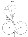
- the fixing device of the present invention is characterized in that the alignment angle ⁇ of the peeling member for the fuser roller is set in a range -5° ⁇ ⁇ ⁇ 25° relative to the tangent line of the outlet of the fixing nip portion.
- FIG. 1 is an illustration of the entire structure of an image forming apparatus, showing an embodiment of a fixing device according to the present invention.
- the rotary developing device 6 comprises a yellow developing unit 6Y, a magenta developing unit 6M, a cyan developing unit 6C, and a black developing unit 6B which are attached to a support frame 8.
- the support frame 8 is driven to rotate by a driving motor (not shown).
- the rotary developing device 6 is rotated and moved such that one of these developing units 6Y, 6C, 6M, 6K is selectively disposed to face the image carrier 3 for every rotation of the image carrier 3.
- Each of the developing units 6Y, 6C, 6M, 6K has a toner storage portion for storing toner of the corresponding color.
- the yellow developing unit 6Y is moved so that its developing roller 6a is brought in contact with a portion of the image carrier 3 where the electrostatic latent image has been formed, thereby forming an yellow toner image on the image carrier 3.
- the toner image thus formed on the image carrier 3 is transferred to the intermediate transfer belt 11 by the primary transfer roller 12.
- the secondary transfer roller 14 is spaced apart from the intermediate transfer belt 11.
- the fixing device 19 comprises a heating fixing member 21 composed of a fuser roller having a heat source and a pressure member 22 composed of a pressure roller to be pressed against the fuser roller.
- the fuser roller 21 and the pressure roller 22 are arranged such that the angle formed between a line connecting the axis of the fuser roller 21 and the axis of the pressure roller 22 and a horizontal line becomes ⁇ .
- the angle ⁇ is defined as 0° ⁇ ⁇ ⁇ 30°.
- the pressure roller 22 comprises a cylindrical body 22b made of a metal, a rotary shaft 22d fixed to the cylindrical body 22b, the bearings 25 supporting the rotary shaft 22d, an elastic layer 22c provided on the outer periphery of the cylindrical body 22b, and an outer layer (not shown) made of fluoro rubber, fluoro resin coating on the surface of the elastic layer 22c, similarly to the fuser roller 21.
- the thickness of the elastic layer 21c of the fuser roller 21 is extremely smaller than the thickness of the elastic layer 22c of the pressure roller 22, thereby forming a fixing nip portion N where the pressure roller 22 is concaved.
- the peeling member 32 for the pressure roller 22 has a similar configuration as the peeling member for the fuser roller 21. As shown in Fig. 2 and Fig. 3, the end of a peeling portion 32a is positioned on the further downstream side in the recording medium feeding direction relative to the end of the peeling portion 31a. The ends of guide portions 32e are in contact with the outer peripheries of the bearings 25 of the pressure roller 22 at points P, whereby the gap between the end of the peeling portion 32a and the surface of the pressure roller 22 is always held constant.
- the peeling members 31, 32 are arranged on the downstream side in the recording medium feeding direction relative to the nip portion N to extend in the axial direction of the fuser roller 21 and the pressure roller 22.
- the end portion of the peeling member 31 for the fuser roller 21 is arranged to be inclined toward the outlet of the nip portion N such that the end of the peeling portion 31a is in non-contact with and in proximity to the fuser roller 21.
- the end of the peeling member 32 for the pressure roller 22 is positioned on the further downstream side in the recording medium feeding direction relative to the end of the peeling member 31.
- the peeling member 31 for the fuser roller 21 is biased toward the housing 24 by the springs 33, whereby the ends of the guide portions 31e are in contact with the fuser roller 21.
- the gap between the end of the peeling portion 31a and the surface of the fuser roller 21 is positioned to be always held constant.
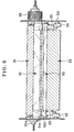
- the peeling member 32 for the pressure roller 22 has a similar configuration as the peeling member for the fuser roller 21. As shown in Fig. 2 and Fig. 3, the end of the peeling portion 32a is positioned on the further downstream side in the recording medium feeding direction relative to the end of the peeling portion 31a. The ends of the guide portions 32e are in contact with the outer peripheries of the bearings 25 of the pressure roller 22 at the points P, whereby the gap between the end of the peeling portion 32a and the surface of the pressure roller 22 is positioned to be always held constant. Therefore, as shown in Fig. 6, the length of the pressure roller 22 in the axial direction is shorter than that of the fuser roller 21. The bearings 25 are arranged in spaces formed because of difference in length so that the pressure roller 22 is supported by the bearings 25 at both sides of the pressure roller 22.
- the fuser roller 21 and the pressure roller 22 are aligned in substantially the horizontal direction and a method of feeding a recording medium out of the fixing nip N upwardly is employed, the recording medium easily winds around the fuser roller 21 so that the recording medium always comes in contact with the peeling member 31, that is, the frequency in use of the peeling member is high.
- the setting of the alignment angle of the peeling member relative to the recording medium is important. If the alignment angle of the peeling member 31 relative to the recording medium is not good, the peeling performance of recording media should be poor and linear defects may be created on image.
- thermoplastic fluoro resins such as tetrafluoroethylene/perfluoroalkyl vinyl ether copolymer (PFA), tetrafluoroethylene resin (PTFE), tetrafluoroethylene hexafluoropropylene copolymer (FEP), ehtylene tetrafluoroethylene copolymer (ETFE), ethylene chlorotrifluoroethylene copolymer (ECTFE), Polychlorotrifluoroethylene (PCTFE), polyvinyl fluoride (PVF), tetrafluoroethylene hexafluoropropylene perfluoroalkoxy vinyl ether copolymer (EPE), and polyvinylidene fluoride resin (PVDF), thermoplastic elastomers, other fluoro copolymer resins, and fluorocarbon such as (CF)N and (C2F)F.
- PVF tetrafluoroethylene/perfluoroalkyl vinyl ether copo
- the gap between the end of the peeling member 31 and the fuser roller 21 must be held always constant over the entire length in the axial direction of the fuser roller 21.
- the fuser roller 21 and the pressure roller 22 are normally biased against each other by force F of the springs 27 (Fig. 2) at the both ends in the axial direction of the rollers so that the middle portion of the pressure roller 22 bulges because the elastic layer of the pressure roller 22 is thick.
- the surface of the fuser roller 21 is deflected into an arc shape in the axial direction. Therefore, there is a problem that it is very difficult to control the gap between the peeling member 31 and the surface of the fuser roller 21.
- the fuser roller 21 and the pressure roller 22 are generally arranged one above the other to be aligned in the vertical direction, a force acts on the recording medium, going out of the nip portion, in a direction moving apart from the fuser roller because of gravitation so that the prospect of peeling the recording medium by the peeling member is low.
- the fuser roller 21 and the pressure roller 22 are aligned in substantially the horizontal direction as shown in Fig. 1, the recording medium easily winds around the fuser roller 21 so that the recording medium going out of the nip portion N always comes in contact with the peeling member, that is, the frequency in use of the peeling member is extremely high as compared to the conventional one. Accordingly, the control of the aforementioned gap is a matter of further importance.
- Fig. 12 is a sectional view showing one embodiment of the present invention.
- the fuser roller 21 is biased against the pressure roller 22 by force F of the springs 27 (Fig. 2) at the both ends in the axial direction thereof, the longitudinal section through the axis of the metal cylindrical body 21b is formed in a hourglass-like shape and the surface of the elastic layer 22c is formed in an arc shape.
- the fuser roller 21 is frequently formed in an inversed crown shape (having side portions of which diameter is larger than that of the middle portion thereof) for preventing the creation of creases. This also increases the tendency of arc shape.
- the end portion 31f of the peeling member 31 is formed in an arc shape in order to make the gap G between the end portion 31f of the peeling member 31 and the elastic layer 22c constant.
- the gap G is measured by a micro gauge or a laser displacement gauge.
- Fig. 13 is a sectional view of another embodiment of the present invention.
- the end portion 31f of the peeling member 31 is formed such that gap G2 between the end of the peeling member 31 and the surface of the fuser roller 21 at the both side portions thereof is greater than the gap G1 between the end of the peeling member 31 and the surface the fuser roller 21 at the middle portion thereof.
- the middle portion of the peeling member 31 (the portion first comes in contact with the recording medium) is proximal to the fuser roller 21.
- the control of the gap is facilitated so that the peeling member 31 can be easily manufactured without losing substantial peeling performance. Since the portion in proximity to the fuser roller 21 is reduced, the damage of the peeling member 31 and the fuser roller 21 due to object matters or paper jam is reduced, thereby improving the durability and the reliability of the peeling member 31 and the fuser roller 21.
- the present invention has been described with reference to the embodiments disclosed herein, the present invention is not limited thereto and various changes may be made therein.
- the present invention may be adopted to conventionally known techniques and these techniques may be combined.
- the peeling member 31 for the fuser roller 21 has bee explained in the aforementioned embodiments, the present invention may be adopted to the peeling member 32 for the pressure roller 22.
Landscapes
- Physics & Mathematics (AREA)
- General Physics & Mathematics (AREA)
- Fixing For Electrophotography (AREA)
Applications Claiming Priority (10)
| Application Number | Priority Date | Filing Date | Title |
|---|---|---|---|
| JP2002065099A JP2003263062A (ja) | 2002-03-11 | 2002-03-11 | 定着装置 |
| JP2002065100A JP2003263063A (ja) | 2002-03-11 | 2002-03-11 | 画像形成装置 |
| JP2002065099 | 2002-03-11 | ||
| JP2002065101A JP3972184B2 (ja) | 2002-03-11 | 2002-03-11 | 定着装置 |
| JP2002065100 | 2002-03-11 | ||
| JP2002065101 | 2002-03-11 | ||
| JP2002071722A JP2003270996A (ja) | 2002-03-15 | 2002-03-15 | 定着装置 |
| JP2002071723A JP2003270997A (ja) | 2002-03-15 | 2002-03-15 | 定着装置 |
| JP2002071723 | 2002-03-15 | ||
| JP2002071722 | 2002-03-15 |
Publications (1)
| Publication Number | Publication Date |
|---|---|
| EP1345093A2 true EP1345093A2 (fr) | 2003-09-17 |
Family
ID=27767939
Family Applications (1)
| Application Number | Title | Priority Date | Filing Date |
|---|---|---|---|
| EP03004945A Withdrawn EP1345093A2 (fr) | 2002-03-11 | 2003-03-10 | Dispositif de fixage |
Country Status (3)
| Country | Link |
|---|---|
| US (1) | US6839537B2 (fr) |
| EP (1) | EP1345093A2 (fr) |
| CN (2) | CN2629070Y (fr) |
Cited By (1)
| Publication number | Priority date | Publication date | Assignee | Title |
|---|---|---|---|---|
| EP1965270A1 (fr) * | 2007-03-02 | 2008-09-03 | Samsung Electronics Co., Ltd. | Guidage d'évacuation et dispositif de formation d'images comportant celui-ci |
Families Citing this family (14)
| Publication number | Priority date | Publication date | Assignee | Title |
|---|---|---|---|---|
| JP2004191923A (ja) * | 2002-10-18 | 2004-07-08 | Seiko Epson Corp | トナー、定着装置および画像形成装置 |
| JP2004191921A (ja) * | 2002-10-18 | 2004-07-08 | Seiko Epson Corp | トナー、定着装置および画像形成装置 |
| JP2004191922A (ja) * | 2002-10-18 | 2004-07-08 | Seiko Epson Corp | トナー、定着装置および画像形成装置 |
| JP4120357B2 (ja) * | 2002-11-05 | 2008-07-16 | セイコーエプソン株式会社 | トナーの製造方法、トナー、定着装置および画像形成装置 |
| JP2005091545A (ja) * | 2003-09-16 | 2005-04-07 | Brother Ind Ltd | 定着装置および画像形成装置 |
| US7415233B2 (en) | 2003-11-27 | 2008-08-19 | Ntn Corporation | Plate-shaped peeling member and method and apparatus of manufacturing same |
| JP4264410B2 (ja) * | 2004-11-30 | 2009-05-20 | 株式会社リコー | 定着装置および画像形成装置 |
| JP2008065264A (ja) * | 2006-09-11 | 2008-03-21 | Ricoh Co Ltd | 定着装置及び画像形成装置 |
| JP4770958B2 (ja) * | 2009-03-26 | 2011-09-14 | 富士ゼロックス株式会社 | 定着装置及びこれを備えた画像形成装置 |
| JP4988876B2 (ja) * | 2010-01-26 | 2012-08-01 | 株式会社沖データ | 定着装置及び画像形成装置 |
| JP2011164324A (ja) * | 2010-02-09 | 2011-08-25 | Canon Inc | ディスプレイの製造方法 |
| US20110221841A1 (en) * | 2010-03-09 | 2011-09-15 | Xerox Corporation | Stripping blade for stripping media from a drum in an inkjet printer |
| US8313190B2 (en) * | 2010-03-11 | 2012-11-20 | Xerox Corporation | System and method for stripping media from an offset imaging member in an inkjet printer |
| JP2012193015A (ja) * | 2011-03-16 | 2012-10-11 | Ricoh Co Ltd | シート分離装置、定着装置、および画像形成装置 |
Family Cites Families (4)
| Publication number | Priority date | Publication date | Assignee | Title |
|---|---|---|---|---|
| US4156524A (en) * | 1977-06-23 | 1979-05-29 | Xerox Corporation | Roll fuser stripping mechanism |
| JP3622526B2 (ja) | 1997-10-16 | 2005-02-23 | 富士ゼロックス株式会社 | 画像記録装置 |
| JP2001242738A (ja) * | 2000-02-29 | 2001-09-07 | Sharp Corp | 定着装置 |
| JP2003076182A (ja) * | 2001-06-22 | 2003-03-14 | Ricoh Co Ltd | 定着装置および画像形成装置 |
-
2003
- 2003-03-10 US US10/384,061 patent/US6839537B2/en not_active Expired - Fee Related
- 2003-03-10 EP EP03004945A patent/EP1345093A2/fr not_active Withdrawn
- 2003-03-11 CN CNU032404379U patent/CN2629070Y/zh not_active Expired - Lifetime
- 2003-03-11 CN CNB031195733A patent/CN1248066C/zh not_active Expired - Fee Related
Cited By (1)
| Publication number | Priority date | Publication date | Assignee | Title |
|---|---|---|---|---|
| EP1965270A1 (fr) * | 2007-03-02 | 2008-09-03 | Samsung Electronics Co., Ltd. | Guidage d'évacuation et dispositif de formation d'images comportant celui-ci |
Also Published As
| Publication number | Publication date |
|---|---|
| US20030210933A1 (en) | 2003-11-13 |
| CN2629070Y (zh) | 2004-07-28 |
| US6839537B2 (en) | 2005-01-04 |
| CN1248066C (zh) | 2006-03-29 |
| CN1444112A (zh) | 2003-09-24 |
Similar Documents
| Publication | Publication Date | Title |
|---|---|---|
| US6636709B2 (en) | Fixing device having temperature detecting member and image forming apparatus using said fixing device | |
| US7764915B2 (en) | Elastic roll and fixing device | |
| JP4917963B2 (ja) | 定着装置およびそれを備えた電子写真装置 | |
| US7463857B2 (en) | Fixing device with peeling member for an image forming apparatus | |
| US9164435B2 (en) | Fixing device and image forming apparatus | |
| US6839537B2 (en) | Fixing device | |
| US8346149B2 (en) | Fixing device and image forming apparatus incorporating same | |
| US8457540B2 (en) | Fixing device and image forming apparatus incorporating same | |
| US8346147B2 (en) | Fixing unit and image forming apparatus | |
| EP2199868A2 (fr) | Dispositif d'alimentation à courroie et appareil de formation d'images fourni avec celui-ci | |
| US5160130A (en) | Thin-tip stripper finger for use with a fuser roll in an electrophotographic apparatus | |
| JP2005156679A (ja) | 画像形成装置 | |
| JP2014174383A (ja) | 定着装置及び画像形成装置 | |
| JP5635278B2 (ja) | 定着装置及び画像形成装置 | |
| JP6888285B2 (ja) | 転写装置及び画像形成装置 | |
| US20070065189A1 (en) | Fixing device and image forming apparatus | |
| JP2012062194A (ja) | 画像形成装置 | |
| JP5028838B2 (ja) | 画像定着装置および画像形成装置 | |
| JP3985141B2 (ja) | 定着装置 | |
| JP2003270997A (ja) | 定着装置 | |
| JP3940654B2 (ja) | 定着装置と画像形成装置 | |
| JP4532990B2 (ja) | 電子写真装置 | |
| JP7512615B2 (ja) | 定着装置及び画像形成装置 | |
| JP2003316197A (ja) | 定着装置及び画像形成装置 | |
| JP2005266716A (ja) | 定着装置および画像形成装置 |
Legal Events
| Date | Code | Title | Description |
|---|---|---|---|
| PUAI | Public reference made under article 153(3) epc to a published international application that has entered the european phase |
Free format text: ORIGINAL CODE: 0009012 |
|
| AK | Designated contracting states |
Kind code of ref document: A2 Designated state(s): AT BE BG CH CY CZ DE DK EE ES FI FR GB GR HU IE IT LI LU MC NL PT SE SI SK TR |
|
| AX | Request for extension of the european patent |
Extension state: AL LT LV MK RO |
|
| STAA | Information on the status of an ep patent application or granted ep patent |
Free format text: STATUS: THE APPLICATION HAS BEEN WITHDRAWN |
|
| 18W | Application withdrawn |
Effective date: 20101007 |