EP1347449A1 - Procede de fabrication d'un disque optique constitue par un seul disque, element comportant quatre couches adhesives et enroulement de cet element mis en application dans le procede - Google Patents
Procede de fabrication d'un disque optique constitue par un seul disque, element comportant quatre couches adhesives et enroulement de cet element mis en application dans le procede Download PDFInfo
- Publication number
- EP1347449A1 EP1347449A1 EP01995013A EP01995013A EP1347449A1 EP 1347449 A1 EP1347449 A1 EP 1347449A1 EP 01995013 A EP01995013 A EP 01995013A EP 01995013 A EP01995013 A EP 01995013A EP 1347449 A1 EP1347449 A1 EP 1347449A1
- Authority
- EP
- European Patent Office
- Prior art keywords
- layered
- release paper
- disc
- adhesive
- protective sheet
- Prior art date
- Legal status (The legal status is an assumption and is not a legal conclusion. Google has not performed a legal analysis and makes no representation as to the accuracy of the status listed.)
- Withdrawn
Links
Images



Classifications
-
- B—PERFORMING OPERATIONS; TRANSPORTING
- B32—LAYERED PRODUCTS
- B32B—LAYERED PRODUCTS, i.e. PRODUCTS BUILT-UP OF STRATA OF FLAT OR NON-FLAT, e.g. CELLULAR OR HONEYCOMB, FORM
- B32B7/00—Layered products characterised by the relation between layers; Layered products characterised by the relative orientation of features between layers, or by the relative values of a measurable parameter between layers, i.e. products comprising layers having different physical, chemical or physicochemical properties; Layered products characterised by the interconnection of layers
- B32B7/04—Interconnection of layers
- B32B7/06—Interconnection of layers permitting easy separation
-
- G—PHYSICS
- G11—INFORMATION STORAGE
- G11B—INFORMATION STORAGE BASED ON RELATIVE MOVEMENT BETWEEN RECORD CARRIER AND TRANSDUCER
- G11B7/00—Recording or reproducing by optical means, e.g. recording using a thermal beam of optical radiation by modifying optical properties or the physical structure, reproducing using an optical beam at lower power by sensing optical properties; Record carriers therefor
- G11B7/24—Record carriers characterised by shape, structure or physical properties, or by the selection of the material
- G11B7/24018—Laminated discs
- G11B7/24024—Adhesion or bonding, e.g. specific adhesive layers
-
- G—PHYSICS
- G11—INFORMATION STORAGE
- G11B—INFORMATION STORAGE BASED ON RELATIVE MOVEMENT BETWEEN RECORD CARRIER AND TRANSDUCER
- G11B7/00—Recording or reproducing by optical means, e.g. recording using a thermal beam of optical radiation by modifying optical properties or the physical structure, reproducing using an optical beam at lower power by sensing optical properties; Record carriers therefor
- G11B7/24—Record carriers characterised by shape, structure or physical properties, or by the selection of the material
- G11B7/241—Record carriers characterised by shape, structure or physical properties, or by the selection of the material characterised by the selection of the material
- G11B7/252—Record carriers characterised by shape, structure or physical properties, or by the selection of the material characterised by the selection of the material of layers other than recording layers
- G11B7/254—Record carriers characterised by shape, structure or physical properties, or by the selection of the material characterised by the selection of the material of layers other than recording layers of protective topcoat layers
- G11B7/2542—Record carriers characterised by shape, structure or physical properties, or by the selection of the material characterised by the selection of the material of layers other than recording layers of protective topcoat layers consisting essentially of organic resins
-
- G—PHYSICS
- G11—INFORMATION STORAGE
- G11B—INFORMATION STORAGE BASED ON RELATIVE MOVEMENT BETWEEN RECORD CARRIER AND TRANSDUCER
- G11B7/00—Recording or reproducing by optical means, e.g. recording using a thermal beam of optical radiation by modifying optical properties or the physical structure, reproducing using an optical beam at lower power by sensing optical properties; Record carriers therefor
- G11B7/24—Record carriers characterised by shape, structure or physical properties, or by the selection of the material
- G11B7/26—Apparatus or processes specially adapted for the manufacture of record carriers
-
- G—PHYSICS
- G11—INFORMATION STORAGE
- G11B—INFORMATION STORAGE BASED ON RELATIVE MOVEMENT BETWEEN RECORD CARRIER AND TRANSDUCER
- G11B7/00—Recording or reproducing by optical means, e.g. recording using a thermal beam of optical radiation by modifying optical properties or the physical structure, reproducing using an optical beam at lower power by sensing optical properties; Record carriers therefor
- G11B7/24—Record carriers characterised by shape, structure or physical properties, or by the selection of the material
- G11B7/241—Record carriers characterised by shape, structure or physical properties, or by the selection of the material characterised by the selection of the material
- G11B7/252—Record carriers characterised by shape, structure or physical properties, or by the selection of the material characterised by the selection of the material of layers other than recording layers
-
- G—PHYSICS
- G11—INFORMATION STORAGE
- G11B—INFORMATION STORAGE BASED ON RELATIVE MOVEMENT BETWEEN RECORD CARRIER AND TRANSDUCER
- G11B7/00—Recording or reproducing by optical means, e.g. recording using a thermal beam of optical radiation by modifying optical properties or the physical structure, reproducing using an optical beam at lower power by sensing optical properties; Record carriers therefor
- G11B7/24—Record carriers characterised by shape, structure or physical properties, or by the selection of the material
- G11B7/241—Record carriers characterised by shape, structure or physical properties, or by the selection of the material characterised by the selection of the material
- G11B7/252—Record carriers characterised by shape, structure or physical properties, or by the selection of the material characterised by the selection of the material of layers other than recording layers
- G11B7/256—Record carriers characterised by shape, structure or physical properties, or by the selection of the material characterised by the selection of the material of layers other than recording layers of layers improving adhesion between layers
Definitions
- This invention relates to a method for manufacturing an optical disc, and more particularly, to an optical disc such as a digital video recorder (hereinafter referred to DVR) which is adapted so that a pit surface of the single layered disc is protected by a protective sheet.
- DVR digital video recorder
- Computers, among others, personal computers and the like have recently been remarkably popularized and accordingly storage mediums for use therein, especially the capacity of the optical disc has been highly densified more and more, thereby requiring many types thereof.
- the optical disc there are, for example, a digital video disc-random access memory, and a digital video disc-random memory (hereinafter referred to as DVD-RAM, DVD-RW and the like, all of them are manufactured by laminating two discs.
- DVD-RAM digital video disc-random access memory
- DVD-RW digital video disc-random memory
- This type of DVR has memory capacity approximately five times as much as the conventional DVD, for example, 22.5 gigabytes.
- the optical disc in the form of DVR has been so dimensioned that its thickness is 1.2 mm, external diameter is 120 mm, and the internal diameter of its center hole is 15mm.
- Its sectional configuration is such that information applied pit is formed one side of a single layered disc, and that the pit is protected and covered by resin material.
- the protective layer is of 0.1 mm and is adapted to read out an information applied to the pit by means of a blue laser of a wave length, for example of 405 nanometer.
- this method when used does not necessarily develop the ultraviolet light curable resin the single layered disc as a whole evenly.
- this type of DVR requires extremely uniform protective layer if the aforementioned blue laser is used since the distance to the recording layer is specified as 0.1 mm.
- an adhesive may be outwardly scattered at any rate by centrifugal force to circumferentially stain while get scattered and lost to lower an effective usage rate.
- means or the like for irradiating the ultraviolet light is required so that a large scaled device or means for forming the protective layer, thereby increasing a cost.
- the present invention is provided to solve the aforementioned problem.
- a further object of the invention is to provide a four layered adhesive sheet member for use as well as a rolled member.
- a first aspect of the invention resides in a method for manufacturing optical disc to allow a protective sheet with an adhesive layer to abut against a single layered adhesive sheet member and then a protective sheet being bonded to the single layered disc.
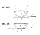
- a second aspect of the invention resides in the method for manufacturing optical disc wherein there is composed of an elongated release paper, a protective sheet temporarily attached to the elongated release paper, an adhesive layer on the protective sheet, a release paper tacked to the adhesive layer, wherein the release paper is allowed to expose the adhesive layer, a three layered adhesive sheet from which the release sheet is released is adapted to abut against the surface of the single layered disc to transport and bond the surface of the single layered disc, and wherein the elongated release paper is released from the protective sheet bonded to the single layered disc to thereby expose the protective sheet on the single layered disc.
- a third aspect of the invention resides in the method for manufacturing optical disc wherein the adhesive layer is exposed by releasing the release paper from the four layered adhesive sheet is composed of an elongated release paper, a protective sheet temporarily attached to the elongated release paper, an adhesive layer on the protective sheet, a release paper temporarily adhesive to the adhesive layer, wherein the release paper is released from the four layered adhesive sheet to abut against the surface of the single layered disc to transport and bond the surface of the single layered disc through the adhesive layer, and wherein the elongated release paper is released from the protective sheet bonded to the single layered disc to thereby expose the protective sheet on the single layered disc and thereafter, the single layered disc is pressured by an atmosphere of an air pressure to eliminate air bubble.
- a fourth aspect of the invention resides in the method for manufacturing optical disc wherein the adhesive sheet member is so pressed against the single layered disc as to enlarge the area of contact thereof from the center below to outside when the three layered adhesive sheet member abuts against the surface of the single layered disc.
- a fifth aspect of the invention resides in the method for manufacturing optical disc wherein the adhesive sheet member is pressed against the single layered disc by a roller when the three layered adhesive sheet member abuts against the surface of the single layered disc.
- a sixth aspect of the invention resides in the method for manufacturing optical disc wherein the protective sheet is formed of polycarbonate resin.
- a seventh aspect of the invention resides in the method for manufacturing optical disc wherein a release paper is polyethylene terephthalate resin as processed by silicone.
- a eighth aspect of the invention resides in the method for manufacturing optical disc wherein an elongated release paper is polyethylene terephthalate resin as processed by silicone.
- a ninth aspect of the invention resides in the method for manufacturing optical disc wherein pneumatic pressure is more than 10kg/cm 3 .
- a tenth aspect of the invention resides in the four layered adhesive sheet which is employed when the optical disc is manufactured wherein said four layered adhesive sheet member comprises an elongated release paper, a protective sheet adapted to longitudinally, temporarily adhere to the elongated release paper at regular intervals, an adhesive layer formed on the protective sheet, and a release paper adapted to temporarily adhere to the adhesive layer and wherein an opening bored through the four layered adhesive sheet.
- the eleventh feature of the invention resides in four layered adhesive sheet member wherein the protective sheet is formed of polycarbonate resin whereas the adhesive layer of the protective sheet is formed of acrylic adhesive.
- the twelfth feature of the invention resides in the roll member formed by winding the four layered adhesive sheet member used for manufacturing the optical disc into a cylinder in a mandrel form which is employed when the optical disc is manufactured wherein said four layered adhesive sheet member comprises an elongated release paper, a protective sheet adapted to longitudinally, temporarily adhere to the elongated release paper at regular intervals, an adhesive layer formed on the protective sheet, and a release paper adapted to temporarily adhere to the an adhesive layer, and wherein an opening bored through the four layered adhesive sheet.
- the thirteenth feature of the invention resides in the rolled member wherein the four layered adhesive sheet member is wound around a mandrel cylinder with a center hole through non-adhesive attached sheet.
- the invention may be practiced in combination with more than two defined arrangements selected from the aforementioned aspects 1-13.
- uniform protective layer may be formed.
- the thickness of the protective layer as the single layered optical may readily changed by only change the thickness of protective sheet 1B out of the adhesive sheets, the protective layer may be formed evenly on the surface of the single layered with neither any air bubbles nor crease. Because of use of the four layered adhesive sheet, more effective optical disc may be possibly obtained.
- this invention does not necessitate step of developing the adhesive and of irradiating the ultraviolet beam thereby curtailing numbers of manufacturing steps or processes.
- Fig.1 shows a representation of the four adhesive layered sheet member.
- FIG. 1(A) is a side view thereof
- FIG.1 (B) is a plan view thereof.
- the four adhesive sheet member, the single layered disc, and the optical disc those of which as a matter of convenience and for facilitating the understanding are shown in a manner of exaggeration of their thickness (for this reason, it is not necessarily accurate with respect to relation between length and breadth of magnification).
- a four layered adhesive sheet member 1 used herein is a multilayered adhesive sheet member which is composed of an elongated release paper 1A, a specifically speaking, the four layered adhesive sheet member 1 comprises the elongated release paper 1A, the protective sheet 1B [the elongated release paper 1A is temporarily adheres to the protective sheet 1B by an adhesive layer, (for example, acrylic pressure sensitive adhesive layer) not shown, in thickness on the order of 2 ⁇ 3 ⁇ m], an adhesive layer 1C, and a release paper 1D allowed to temporarily adhere to the adhesive layer, the elongated release paper 1A being integrally formed with the protective sheet 1B, the adhesive layer 1C, the release paper 1D superposed thereon and bonded thereto at a distance.
- an adhesive layer for example, acrylic pressure sensitive adhesive layer
- Those of the protective sheet 1B, the adhesive layer 1C, and the release paper 1D are in a form of a long playing record sheet and many of them temporarily bonded longitudinally at a certain distance to the surface of the elongated release paper 1A is made of an elongated synthetic resin tape and served as a base of the four layered adhesive sheet member 1, which is so called "carrier".
- the elongated release paper 1A includes the protective sheet 1B temporarily attached.
- the protective sheet 1B as will be later described, is so arranged to transfer from the elongated release paper 1A and then adhere to the single layered disc 2 to protect a bit surface thereof.
- the elongated release paper 1A and the protective sheet 1b may be both temporarily attached by acrylic adhesive layer.
- the adhesive layer 1C is provided with the surface to interpose between the single layered disc 2 and the protective sheet 1B to bond both of them.
- the release paper 1D is temporarily attached to the adhesive layer 1C to cover the surface therewith thus preventing the adhesive layer from staining the latter.
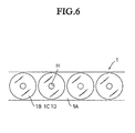
- the four layered adhesive sheet member 1 is formed in its center with ahole H bored through the elongated release paper 1A, the protective sheet 1B, the adhesive layer 1C, and the release paper 1D simultaneously to correspond to the hole in the single layered disc 2.
- the hole H is used when the four layered adhesive sheet member 1 is positioned with respect to a holding table.
- the four layered adhesive sheet member 1 may employ, for example, a thin paper material such as polyethylene or the like and be, for example, up to 50 ⁇ m.
- a thin paper material such as polycarbonate resin which is excellent in hardness and strength to sufficiently protect a pit surface of the single layered disc is employed in thickness, for example, 70 ⁇ m.
- the adhesive layers 1C such as, for example, mainly, pressure sensitive adhesives, for example, rubber adhesive, acrylic adhesive, silicone adhesive, vinyl adhesive and the like are employed, each of them is of thickness, for example, 30 ⁇ m.
- PET(polyethylene terephthalate) and the like is employed as the release paper 1D and is dimensioned as thickness of 50 ⁇ m.
- a layer of thickness of each of the elongated release paper 1A, the protective sheet 1B, the adhesive layer 1C, especially, these two protective sheet 1B and the adhesive sheet 1C may determine or select optimum thickness according to types of the optical discs as designed.
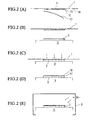
- FIG.2(A) ⁇ Figs.2(E) shows successively the steps for manufacturing the optical disc according to the invention.
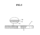
- the single layered disc 2 is positioned within a pressure container 5 while placing on the holding table 3 and being subjected to the air pressure.
- the air pressure serves to exhaust the air contained in the adhesive layer.
- the applied pressure in this instance, preferably, more than 10 kg/cm 2 [980665(Pa)]may be employed in view of efficiency of exhaust of the air bubbles(see Fig.5).
- the protective layer formed on the surface (one side) is extremely uniformalized since the protective layer is in a condition in which the protective sheet 1B is held applied to the surface of the single layered disc 2 by the adhesive so that uniformity may be guaranteed so long as the protective sheet 1B to be used is uniform.
- Fig.6 a plan view of the four layered adhesive sheet member used in the method for manufacturing the optical disc.
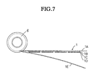
- Fig. 7 is a side view showing the four layered adhesive sheet which is fed out from the mandrel cylinder.
- Fig. 8 is a perspective view showing the rolled member around which the four layered adhesive sheet member is wound.
- the four layered adhesive sheet member 1 comprises the elongated release paper 1A, the protective sheet 1B, the adhesive layer 1C formed on the protective sheet, and the release paper 1D temporarily attached to the adhesive layer.
- the rolled member X is so fabricated as to wind the release paper around collared mandrel cylinder 61 by non-adhesive attached paper 1E in thickness on the order of 60 ⁇ m, for example, (normally so called "interleaving paper") so as prevent inadvertently peeled release paper from sticking to the back side of the elongated release paper 1A.
- the elongated four layered adhesive sheet member 1 is fabricated to form the rolled member X to feed out the member in a smooth manner.
- a support shaft as a part of the optical disc manufacturing apparatus is inserted into a mandrel hole 61 of the collared mandrel cylinder 6 to rotatably support the rolled member X assuming a posture of standing by ready to feed out.
- this step if applied, high quality of the optical disc D may be manufactured.
- This invention relates to a method for manufacturing an optical disc composed of a single layered disc.
- optical disc Digital Video Recorder
- This invention may be applicable to any memory disc without departing from its principal and adaptable to any field so long as the same effect may be expected.
Landscapes
- Engineering & Computer Science (AREA)
- Manufacturing & Machinery (AREA)
- Optical Record Carriers And Manufacture Thereof (AREA)
- Manufacturing Optical Record Carriers (AREA)
- Laminated Bodies (AREA)
Applications Claiming Priority (5)
| Application Number | Priority Date | Filing Date | Title |
|---|---|---|---|
| JP2000402268 | 2000-12-28 | ||
| JP2000402268 | 2000-12-28 | ||
| JP2001182565A JP3564664B2 (ja) | 2000-12-28 | 2001-06-15 | ディスク単板からなる光ディスクの製造方法、それに使用される4層接着シート体、及びその巻回体 |
| JP2001182565 | 2001-06-15 | ||
| PCT/JP2001/011451 WO2002054399A1 (fr) | 2000-12-28 | 2001-12-26 | Procede de fabrication d'un disque optique constitue par un seul disque, element comportant quatre couches adhesives et enroulement de cet element mis en application dans le procede |
Publications (2)
| Publication Number | Publication Date |
|---|---|
| EP1347449A1 true EP1347449A1 (fr) | 2003-09-24 |
| EP1347449A4 EP1347449A4 (fr) | 2005-08-10 |
Family
ID=26607159
Family Applications (1)
| Application Number | Title | Priority Date | Filing Date |
|---|---|---|---|
| EP01995013A Withdrawn EP1347449A4 (fr) | 2000-12-28 | 2001-12-26 | Procede de fabrication d'un disque optique constitue par un seul disque, element comportant quatre couches adhesives et enroulement de cet element mis en application dans le procede |
Country Status (5)
| Country | Link |
|---|---|
| EP (1) | EP1347449A4 (fr) |
| JP (1) | JP3564664B2 (fr) |
| CN (1) | CN1220983C (fr) |
| TW (1) | TW550547B (fr) |
| WO (1) | WO2002054399A1 (fr) |
Cited By (2)
| Publication number | Priority date | Publication date | Assignee | Title |
|---|---|---|---|---|
| EP1384575A1 (fr) * | 2002-07-24 | 2004-01-28 | LINTEC Corporation | Feuille stratifiée et Procedés de Production de celles-ci |
| EP1513145A2 (fr) * | 2002-04-08 | 2005-03-09 | Fuji Photo Film Co., Ltd. | Support d'enregistrement optique d'informations et son procédé de fabrication |
Families Citing this family (4)
| Publication number | Priority date | Publication date | Assignee | Title |
|---|---|---|---|---|
| TWI242206B (en) | 2001-06-22 | 2005-10-21 | Fuji Photo Film Co Ltd | Optical information recording medium |
| TW200300932A (en) | 2001-11-30 | 2003-06-16 | Fuji Photo Film Co Ltd | Information recording medium |
| DE60326895D1 (de) * | 2002-01-23 | 2009-05-07 | Fujifilm Corp | Optisches Informationsaufzeichnungsmedium |
| JP5028859B2 (ja) * | 2006-05-12 | 2012-09-19 | ティアック株式会社 | 印刷装置 |
Family Cites Families (4)
| Publication number | Priority date | Publication date | Assignee | Title |
|---|---|---|---|---|
| EP0384041B1 (fr) * | 1989-02-24 | 1994-06-29 | Agfa-Gevaert N.V. | Procédé pour la production d'un matériau d'enregistrement thermosensible |
| JP3583269B2 (ja) * | 1996-11-14 | 2004-11-04 | パイオニア株式会社 | 貼り合わせ型光ディスクの製造方法 |
| JP3014979B2 (ja) * | 1997-01-21 | 2000-02-28 | 日東電工株式会社 | 光ディスク製造方法およびそれに用いる装置 |
| JP2000067468A (ja) * | 1998-08-25 | 2000-03-03 | Teijin Ltd | 光ディスクおよびその製造方法 |
-
2001
- 2001-06-15 JP JP2001182565A patent/JP3564664B2/ja not_active Expired - Fee Related
- 2001-12-25 TW TW090132135A patent/TW550547B/zh active
- 2001-12-26 EP EP01995013A patent/EP1347449A4/fr not_active Withdrawn
- 2001-12-26 CN CN01806919.3A patent/CN1220983C/zh not_active Expired - Fee Related
- 2001-12-26 WO PCT/JP2001/011451 patent/WO2002054399A1/fr not_active Ceased
Cited By (2)
| Publication number | Priority date | Publication date | Assignee | Title |
|---|---|---|---|---|
| EP1513145A2 (fr) * | 2002-04-08 | 2005-03-09 | Fuji Photo Film Co., Ltd. | Support d'enregistrement optique d'informations et son procédé de fabrication |
| EP1384575A1 (fr) * | 2002-07-24 | 2004-01-28 | LINTEC Corporation | Feuille stratifiée et Procedés de Production de celles-ci |
Also Published As
| Publication number | Publication date |
|---|---|
| TW550547B (en) | 2003-09-01 |
| WO2002054399A1 (fr) | 2002-07-11 |
| EP1347449A4 (fr) | 2005-08-10 |
| CN1220983C (zh) | 2005-09-28 |
| CN1419694A (zh) | 2003-05-21 |
| JP3564664B2 (ja) | 2004-09-15 |
| JP2002260302A (ja) | 2002-09-13 |
Similar Documents
| Publication | Publication Date | Title |
|---|---|---|
| US7537816B2 (en) | Laminate sheet | |
| JP3837320B2 (ja) | 光ディスクの貼合装置 | |
| EP1854855B1 (fr) | Feuille multicouche, enroulement de feuille multicouche, et procédé de fabrication idoine | |
| EP0855703B1 (fr) | Methode de laminage de substrats de disques | |
| CN100389021C (zh) | 叠层片及其制造方法 | |
| US20030116266A1 (en) | Method for manufacturing optical disk formed of single disk, and four-layer adhered sheet body and wound body of the sheet body used for the method | |
| JP4087169B2 (ja) | 積層シートおよびその製造方法 | |
| JP3971391B2 (ja) | 光ディスク製造用のアライメント装置 | |
| JP4540299B2 (ja) | 積層シートの巻取体およびその製造方法 | |
| JP3564664B2 (ja) | ディスク単板からなる光ディスクの製造方法、それに使用される4層接着シート体、及びその巻回体 | |
| JP4574221B2 (ja) | ラベル用紙 | |
| US20060180271A1 (en) | Optical recording medium and manufacturing method thereof | |
| JP4432300B2 (ja) | 光学記録媒体の製造方法 | |
| JP2003132593A (ja) | 光ディスクの製造方法 | |
| JP3924253B2 (ja) | 光ディスクの製造方法 | |
| JP3924240B2 (ja) | 光ディスクの製造装置 | |
| JP4698687B2 (ja) | 積層シートおよびその製造方法 | |
| JP2008150613A (ja) | 積層シートおよびその製造方法 | |
| JP2003051139A (ja) | 光透過層形成用シート部材および光学記録媒体の製造方法 | |
| JP2006318610A (ja) | 貼合装置及び貼合方法 | |
| JP2005216425A (ja) | 光ディスクの製造方法 | |
| JP2005222660A (ja) | 光ディスク用基板の製造方法、及び光ディスク | |
| JPH04366478A (ja) | 光ディスク保護用部材およびその用途 | |
| JP2003272258A (ja) | 転写方法及び装置 | |
| JP2004134011A (ja) | 光ディスクの製造方法及び製造装置 |
Legal Events
| Date | Code | Title | Description |
|---|---|---|---|
| PUAI | Public reference made under article 153(3) epc to a published international application that has entered the european phase |
Free format text: ORIGINAL CODE: 0009012 |
|
| 17P | Request for examination filed |
Effective date: 20020827 |
|
| AK | Designated contracting states |
Kind code of ref document: A1 Designated state(s): AT BE CH CY DE DK ES FI FR GB GR IE IT LI LU MC NL PT SE TR |
|
| AX | Request for extension of the european patent |
Extension state: AL LT LV MK RO SI |
|
| RBV | Designated contracting states (corrected) |
Designated state(s): DE FR GB IT NL |
|
| A4 | Supplementary search report drawn up and despatched |
Effective date: 20050623 |
|
| RAP1 | Party data changed (applicant data changed or rights of an application transferred) |
Owner name: KITANO CO., LTD. |
|
| 17Q | First examination report despatched |
Effective date: 20051116 |
|
| STAA | Information on the status of an ep patent application or granted ep patent |
Free format text: STATUS: THE APPLICATION IS DEEMED TO BE WITHDRAWN |
|
| 18D | Application deemed to be withdrawn |
Effective date: 20070228 |