EP1347647B1 - Bordeigenes anzeigesystem - Google Patents
Bordeigenes anzeigesystem Download PDFInfo
- Publication number
- EP1347647B1 EP1347647B1 EP00985947A EP00985947A EP1347647B1 EP 1347647 B1 EP1347647 B1 EP 1347647B1 EP 00985947 A EP00985947 A EP 00985947A EP 00985947 A EP00985947 A EP 00985947A EP 1347647 B1 EP1347647 B1 EP 1347647B1
- Authority
- EP
- European Patent Office
- Prior art keywords
- image information
- information output
- car
- output means
- display
- Prior art date
- Legal status (The legal status is an assumption and is not a legal conclusion. Google has not performed a legal analysis and makes no representation as to the accuracy of the status listed.)
- Expired - Lifetime
Links
Images






Classifications
-
- H—ELECTRICITY
- H04—ELECTRIC COMMUNICATION TECHNIQUE
- H04N—PICTORIAL COMMUNICATION, e.g. TELEVISION
- H04N7/00—Television systems
- H04N7/18—Closed-circuit television [CCTV] systems, i.e. systems in which the video signal is not broadcast
-
- B—PERFORMING OPERATIONS; TRANSPORTING
- B61—RAILWAYS
- B61D—BODY DETAILS OR KINDS OF RAILWAY VEHICLES
- B61D49/00—Other details
-
- B—PERFORMING OPERATIONS; TRANSPORTING
- B61—RAILWAYS
- B61L—GUIDING RAILWAY TRAFFIC; ENSURING THE SAFETY OF RAILWAY TRAFFIC
- B61L15/00—Indicators provided on the vehicle or train for signalling purposes
- B61L15/0018—Communication with or on the vehicle or train
- B61L15/0036—Conductor-based, e.g. using CAN-Bus, train-line or optical fibres
-
- B—PERFORMING OPERATIONS; TRANSPORTING
- B61—RAILWAYS
- B61L—GUIDING RAILWAY TRAFFIC; ENSURING THE SAFETY OF RAILWAY TRAFFIC
- B61L15/00—Indicators provided on the vehicle or train for signalling purposes
- B61L15/0072—On-board train data handling
-
- B—PERFORMING OPERATIONS; TRANSPORTING
- B61—RAILWAYS
- B61L—GUIDING RAILWAY TRAFFIC; ENSURING THE SAFETY OF RAILWAY TRAFFIC
- B61L15/00—Indicators provided on the vehicle or train for signalling purposes
- B61L15/009—On-board display devices
Definitions
- the present invention relates to a display system that is carried on a railroad train to provide passengers in the passenger cars with various information through images.
- Fig. 11 shows a conventional display system mounted on a railroad train.
- the reference characters 1 and 2 respectively denote first and second lead cars disposed at both ends of the train and 3 denotes intermediate cars coupled between the lead cars 1 and 2.
- the lead cars 1 and 2 are equipped with a driver's cab and train driving means, though not shown in the figure.
- An image signal outputted from the image information output means 4a is distributed to the individual cars 1 to 3 through the image information transmission path 6a.
- the branch means 7a extracts the image signal from the image information transmission path 6a and gives it as input to the image display means 8 to cause it to display the image.
- the conventional display system carried on the train is constructed as shown above.
- it has the problem that the image signal cannot be distributed to the individual cars when the image information output means carried on the first lead car breaks down.
- the image information output means breaks down by an accident such as derailment, fire, etc., it cannot provide passengers with evacuation information through image on the display means.
- the train in which the image information output means is absent i.e. the train containing the second lead car, cannot distribute image information.
- the present invention has been made to solve the problems shown above, and an object of the invention is to obtain a display system carried on a railroad train which is less likely to get into conditions in which it cannot distribute image information to the cars. Another object is to obtain a display system carried on a train which, even when one train of connected cars is separated into two trains, can distribute image information in both trains of cars.
- the present invention can provide a display system to be carried on a railroad train includes: first image information output means provided in a given car in a train of a plurality of connected cars, for outputting first image information; second image information output means provided in a given car of said train, for outputting second image information; and display means provided in a given car of said train, for switchably displaying said first image information transmitted from said first image information output means and said second image information transmitted from said second image information output means, so that said display means can display image even when one of the first and second image information output means has broken down.
- said first image information output means and said second image information output means are provided in different cars of said train, which reduces the possibility that both the first and second image information output means break down at nearly the same time.
- said first image information output means and said second image information output means output image information for evacuating passengers, so that the safety of passengers can be ensured.
- At least one of said first image information output means and said second image information output means is a hard disk or an optical disk which are susceptible to faults due to vibrations, in which case it is very effective to reduce the possibility that both the first and second image information output means break down at nearly the same time.
- said display means in the display system carried on a railroad train, includes first display means provided in a given car, for switchably displaying said first image information and said second image information, and second display means provided in a car different from said car, for switchably displaying said first image information and said second image information, so that the train of cars can be separated into two trains in such a way that each train includes at least one display means so that both trains can distribute image information.
- said first and second image information output means are provided in cars equipped with driving means and disposed at both ends of said train, so that the train of cars can be separated into two trains in such a way that both trains include image information output means.
- the display system carried on a railroad train includes: first termination means provided in the car in which said second image information output means is provided; second termination means provided in the car in which said first image information output means is provided; a first image information transmission path having its one end connected to said first image information output means and its other end connected to said first termination means; a second image information transmission path having its one end connected to said second image information output means and its other end connected to said second termination means; first branch means for extracting from said first image information transmission path said first image information outputted from said first image information output means and outputting said first image information to said display means; and second branch means for extracting from said second image information transmission path said second image information outputted from said second image information output means and outputting said second image information to said display means, which structure lessens the restriction of the management of the cars.
- the display system carried on a railroad train includes: first termination means provided in the car in which said second image information output means is provided; an image information transmission path having its one end connected to said first image information output means and its other end connected to said first termination means; second termination means provided in a car coupled between the car in which said first image information output means is provided and the car in which said second image information output means is provided; and switching means provided in said car in which said second termination means is provided, for switchably connecting said image information transmission path to said first termination means and to said second termination means, whereby the image information transmission path can be terminated even when the train of cars has been separated into two trains, making it possible to distribute images of good quality.
- the display system carried on a railroad train includes: means for detecting that a car coupled to said car in which said second termination means is provided has been separated therefrom; and control means for controlling the switching by said switching means in accordance with a result of the detection, whereby the terminating resistors can be switched automatically when the cars are separated.
- the display system carried on a railroad train includes image information detecting means for detecting a halt of transmission of said first image information, wherein when said image information detecting means detects a halt of transmission of said first image information, said display means switches its display from said first image information to said second image information, and thus the images displayed by the display means can be switched automatically.
- the display system carried on a railroad train includes: fault detecting means for detecting a fault of said first image information output means; and control means for, when said fault detecting means detects a fault of said first image information output means, controlling said display means to switch the display of said display means from said first image information to said second image information, and thus the image displayed on the display means can be switched automatically.
- a display system to be carried on a railroad train has two sets of image information output means and each display means receives image information from both of the image information output means.
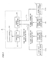
- Fig. 1 is a schematic structural diagram that illustrates a display system carried on a train according to a first preferred embodiment.
- 4a denotes a first image information output means mounted in the lead car 1 to output a first image signal
- 4b denotes a second image information output means also mounted in the lead car 1 to output a second image signal.
- the first image information output means 4a modulates the first image signal and outputs it onto a first channel
- the second image information output means 4b modulates the second image signal and outputs it onto a second channel different from the first channel.
- the reference character 9 denotes synthesizing means for mixing the first channel and the second channel and provides output onto the image information transmission path 6a.
- the first image signal outputted from the first image information output means 4a and the second image signal outputted from the second image information output means 4b are propagated on the image information transmission path 6a and distributed to the individual carts 1 to 3.
- the branch means 7a extracts the first and second image signals from the image information transmission path 6a and provides them as input to the image display means 8.
- the image display means 8 demodulates at least one of the incoming first and second signals and displays the image.
- the display system of the first preferred embodiment has a plurality of image information output means and each display means receives image information from the plurality of image information output means, so that even if any of the image information output means breaks down, another image information output means can distribute image information; therefore the distribution of image information to the display means is not likely to be disabled.
- a coaxial cable can be used as the image information transmission path 6a.
- the image information contained in the first image signal and the image information contained in the second image signal may be the same or different.
- the image display means 8 may demodulate and display one of the first and second image signals or may demodulate and display both signals.
- the two sets of image information output means are mounted in the same car.
- the two image information output means are therefore placed in similar environments (vibrations etc.), they may break down at nearly the same time.
- the display system carried on the train has two sets of image information output means separately disposed in different cars.
- Fig. 2 is a schematic structural diagram that illustrates a train-borne display system of the second preferred embodiment.
- the parts same as or corresponding to those of the conventional system and the system of Fig. 1 are shown at the same reference characters and not described again here.
- the second image information output means 4b shown in Fig. 1 is mounted in the second lead car 2.
- 6b denotes an image information transmission path which has its one end connected to the second image information output means 4b, passes through the intermediate cars 3, and is connected at its other end to the synthesizing means 9.
- the first image signal outputted from the first image information output means 4a is inputted to the synthesizing means 9.
- the second image signal outputted from the second image information output means 4b is inputted to the synthesizing means 9 through the image information transmission path 6b.
- the synthesizing means 9 outputs the incoming first and second image signals onto the first image information transmission path 6a.
- the branch means 7a extracts the first and second image signals from the image information transmission path 6a and inputs them to the image display means 8.
- the image display means 8 demodulates at least one of the incoming first and second image signals and displays the image.
- a plurality of image information output means are separately disposed on different cars, which reduces the possibility that all image information output means will break down at the same time, thus reducing the possibility that the distribution of image information to the display means will be disabled.
- the first and second image information output means may be constructed to be operated by the crew, or to automatically detect an accident such as derailment or fire, so as to output image information for urging the passengers to evacuate.
- the second preferred embodiment is very effective in ensuring the safety of passengers since the two sets of image information output means are not likely to break down at the same time.
- each train includes at least one image information output means so that image information can be distributed in both trains.
- the first lead car and the second lead car are different in the structure of the display system carried on the train. Accordingly the first lead car and the second lead car must be distinguished and differently handled, which restricts the management of the cars. According to a third preferred embodiment, the first lead car and the second lead car are constructed identically in the structure of the display system carried on the train.
- Fig. 3 is a schematic structural diagram that illustrates a display system carried on a train according to the third preferred embodiment.
- the second image information output means 4b shown in Fig. 1 is mounted in the second lead car 2 and both the first and second lead cars are equipped with respective termination means.
- 5b denotes a second termination means provided in the first lead car 1
- 6b denotes an image information transmission path that has its one end connected to the second image information output means 4b, passes through the intermediate cars 3, and has its other end connected to the second termination means 5b
- 7b denotes branch means provided in the first lead car 1, the intermediate cars 3, and the second lead car 2 to branch the image information transmission path 6b
- 9 denotes synthesizing means connected to the image information transmission paths 6a and 6b branched by the branch means 7a and 7b, and for providing the first and second image signals on the transmission paths 6a and 6b as output to the image display means 8.
- the first image signal outputted from the first image information output means 4a is carried on the first image information transmission path 6a and distributed to the cars 1 to 3.
- the first branch means 7a extracts the first image signal from the image information transmission path 6a and outputs it to the synthesizing means 9.
- the second image signal outputted from the second image information output means 4b is carried on the second image information transmission path 6b and distributed to the cars 1 to 3.
- the second branch means 7b extracts the second image signal from the image information transmission path 6b and outputs it to the synthesizing means 9.
- the synthesizing means 9 outputs to the image display means 8 the first and second image signals coming from the first and second branch means 7a and 7b.
- the image display means 8 demodulates at least one of the input first and second image signals and displays the image.
- the first lead car and the second lead car are the same in the structure of the display system carried on the train, which lightens the restriction on the management of the cars.
- the first lead car is equipped with the image information output means, while the second lead car is equipped with the termination means; thus the first and second lead cars are constructed in different ways and must be distinguished in organizing trains.
- the train-borne display system shown in Fig. 3 has an image information output means, a first image information transmission path for transmitting the output from that image information output means, a second image information transmission path connected to another image information output means provided in another car, and a termination resistor for terminating the second image information transmission path; thus the first lead car and the second lead car have the same structure and the trains can be organized without the need to distinguish the first lead car and the second lead car.
- the first to third preferred embodiments have described display systems carried on the train in which each display means receives image signals from a plurality of image information output means.
- a fourth preferred embodiment shows an example of a channel switching method in the image display means shown in the first to third preferred embodiments.
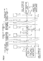
- Fig. 4 is an explanation diagram that illustrates a channel switching method of the fourth preferred embodiment.
- the parts same as or corresponding to those shown in Figs. 1 to 3 are indicated by the same reference characters and not described again here.
- Fig. 4(a) is a schematic diagram illustrating the structure of the first and second image information output means 4a and 4b shown in Figs. 1 to 3 .
- 41 denotes image information recording means in which image information is previously recorded
- 42 denotes image information reading means for reading the image information from the image information recording means 41 and outputting the image information as an image signal
- 43 denotes modulating means for modulating the image signal outputted from the image information reading means 42 and outputting the image signal onto the first or second channel.
- Fig. 4(b) is a schematic diagram illustrating the structure of the image display means 8 shown in Figs. 1 to 3 .
- 81 denotes demodulating means for demodulating a given channel of the input signal
- 82 denotes image information detecting means for detecting whether the demodulated signal contains image information
- 83 denotes channel switch means for switching the channel to be demodulated by the demodulating means 81 when the image information detecting means 82 has detected absence of image information
- 84 denotes a display screen for displaying the image contained in the demodulated signal.
- the first and second image signals outputted from the first and second image information output means 4a and 4b shown in Figs. 1 to 3 are respectively carried on the first and second channels and provided to the image display means 8 shown in Fig. 4(b) .
- the demodulating means 81 demodulates the first channel, for example, and the image contained in the first image signal is displayed on the display screen 84.
- the image information detecting means of Fig. 4(b) detects the absence of image information in the output signal from the demodulating means 81 and the channel switch means 83 receives the detected result and switches the target to be demodulated by the demodulating means 81 from the first channel to the second channel.
- the image information output means 4a and 4b have the image information recording means 41 and the image information reading means 42 in this example, they may contain radio wave receiving means (not shown) that receives an image signal sent through radio wave and outputs the image signal to the modulating means 43, or may contain transmitted signal receiving means (not shown) that receives an image signal sent through a transmission line provided in parallel with the railroad track of the train and outputs the image signal to the modulating means 43.
- Separately disposing the image information output means 4a and 4b in different cars is especially effective when the image information recording means 41 is one that is constructed to be mechanically driven for the reading of the recorded information, e.g. a hard disk head or an optical disk pick-up, since such image information recording means 41 are more likely to break down due to vibrations.
- the image information recording means 41 is one that is constructed to be mechanically driven for the reading of the recorded information, e.g. a hard disk head or an optical disk pick-up, since such image information recording means 41 are more likely to break down due to vibrations.
- the image display means detects the absence of image information in the first channel and switches the display channel from the first channel to the second channel.
- fault detecting means is provided to detect fault of the image information output means and the channel displayed by the image display means is switched in accordance with the detected result.
- Fig. 5 is a schematic structural diagram that illustrates a channel switching method of the fifth preferred embodiment.
- 10a denotes first fault detecting means for detecting fault of the image information output means 4a
- 10b denotes second fault detecting means for detecting fault of the image information output means 4b, where the first fault detecting means is provided in the same car as the first image information output means 4a and the second fault detecting means is provided in the same car as the second image output means.
- the results detected by the first and second fault detecting means are transmitted to the channel switch means 85 in the image display means 8 through the transmission paths 11a and 11b.
- the channel switch means 85 receives the detected results and switches the channel to be demodulated by the demodulating means 81.
- the demodulating means 81 demodulates, for example, the first channel, and displays the image contained in the first image signal on the display screen 84.
- the first fault detecting means 10a detects the fault of the first image information output means 4a and informs the channel switch means 85 of the detected result.
- the channel switch means 85 switches the target demodulated by the demodulating means 81 from the first channel to the second channel.
- a plurality of image information output means are separately disposed in different cars. Then, as already described, when one train of connected cars is separated into two trains, the cars are separated in such a way that each train contains at least one image information output means so that the image information can be distributed in both trains of cars.
- a sixth preferred embodiment shows an example of the train separating method.
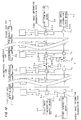
- Fig. 6 is a schematic structural diagram that illustrates a display system carried on a train according to the sixth preferred embodiment.
- the parts same as or corresponding to those shown in Fig. 3 are indicated by the same reference characters and not described again here.
- 3a and 3b denote adjacent intermediate cars; 12a and 12b denote switch means; and 13a and 13b denote termination means.
- the switch means 12a and the termination means 13a are mounted in the intermediate car 3a and the switch means 12b and the termination means 13b are mounted in the intermediate car 3b.
- the switch means 12a separates the first image information transmission path 6a into a transmission path 61 a connected to the first image information output means 4a and a transmission path 62a connected to the termination means 5a and switchably connects the transmission path 61a to the transmission path 62a and to the termination means 13a.
- the switch means 12b separates the second image information transmission path 6b into a transmission path 62b connected to the second image information output means 4b and a transmission path 61b connected to the termination means 5b and switchably connects the transmission path 61b to the transmission path 62b and to the termination means 13b.
- the switch means 12a is connecting the transmission path 61a and the transmission path 62a and the switch means 12b is connecting the transmission path 61b and the transmission path 62b, so that the display system on the train of Fig. 6 operates like that shown in Fig. 3 .
- Fig. 7 illustrates the train of Fig. 6 that has been separated into two trains.
- the parts same as or corresponding to those shown in Fig. 6 are indicated by the same reference characters and not described here again.
- the cars 3a and 3b are separated, with the switch means 12a connecting the transmission path 61a and the termination means 13a and the switch means 12b connecting the transmission path 62b and the termination means 13b.
- the first image signal outputted from the first image information output means 4a is propagated on the transmission path 61a and distributed to the cars from the first lead car 1 to the intermediate car 3a.
- the branch means 7a provided on the transmission path 61a extracts the first image signal from the transmission path 61a and outputs the first image signal to the image display means 8 through the synthesizing means 9.
- the second image signal outputted from the second image information output means 4b is propagated on the transmission path 62b and distributed to the cars from the second lead car 2 to the intermediate car 3b.
- the branch means 7b provided on the transmission path 62b extracts the second image signal from the transmission path 62b and outputs the second image signal to the image display means 8 through the synthesizing means 9.
- the separation of one train into two can be similarly achieved by the method shown in Fig. 8 in the train-borne display system shown in Fig. 2 .
- Fig. 8 the parts same as or corresponding to those shown in Figs. 2 and 7 are indicated by the same reference characters and not described again here.
- the transmission path 61 a is connected to the termination means 13a and the transmission path 62a and the transmission path 62b are connected through the switches 15a and 15b.
- termination means is provided in a given car and switch means is provided in that given car to switchably connect the image information transmission path connected to the image information output means to that termination means and to termination means provided in another car, so that the image information transmission path can be terminated even when the train is separated into two trains, making it possible to distribute image of good quality to each car.
- the termination means and the switch means can be provided in all cars of the train.
- separation detecting means is provided to detect the separation of cars and this detecting means controls the switch means shown in the sixth preferred embodiment.
- Fig. 9 is a schematic structural diagram that illustrates a display system carried on a train according to a seventh preferred embodiment.
- the parts same as or corresponding to those shown in Figs. 6 and 7 are indicated by the same reference characters and not described here again.
- 14a and 14b denote separation detecting means for detecting the separation of cars.
- the separation detecting means 14a and 14b send respective identification signals to each other so that they can recognize that the intermediate car 3a and the intermediate car 3b are coupled together.
- Fig. 10 shows the train of Fig. 9 which has been separated apart.
- the separation detecting means 14a detects the absence of signal reception from the separation detecting means 14b and detects that the intermediate car 3a and the intermediate car 3b have been separated apart. Then it controls the switch means 12a to connect the transmission path 61a to the termination means 13a.
- the separation detecting means 14b detects the absence of signal reception from the separation detecting means 14a and controls the switch means 12b to connect the transmission path 62b to the termination means 13b.
- the separation detecting means for detecting the separation of cars controls the switching to the termination means described in the sixth preferred embodiment.
- the same separation detecting means can be provided in the train-borne display system shown in Fig. 8 .
Landscapes
- Engineering & Computer Science (AREA)
- Mechanical Engineering (AREA)
- Multimedia (AREA)
- Signal Processing (AREA)
- Transportation (AREA)
- Train Traffic Observation, Control, And Security (AREA)
- Details Of Television Systems (AREA)
- Electric Propulsion And Braking For Vehicles (AREA)
Claims (10)
- In einem Eisenbahnzug zu tragendes Anzeigesystem, gekennzeichnet durch:Ausgabemittel (4a) für erste Bildinformationen, die in einem gegebenen Waggon (1) in einem Zug aus mehreren verbundenen Waggons vorgesehen sind, um erste Bildinformationen auszugeben;Ausgabemittel (4b) für zweite Bildinformationen, die in einem gegebenen Waggon (1, 2) des Zugs vorgesehen sind, um zweite Bildinformationen auszugeben; undAnzeigemittel (8), die in einem gegebenen Waggon (1, 2, 3) des Zugs vorgesehen sind, zum umschaltbaren Anzeigen der von den Ausgabemitteln (4a) für erste Bildinformationen übertragenen ersten Bildinformationen und der von den Ausgabemitteln (4b) für zweite Bildinformationen übertragenen zweiten Bildinformationen.
- In einem Eisenbahnzug getragenes Anzeigesystem nach Anspruch 1, bei dem die Ausgabemittel (4a) für erste Bildinformationen und die Ausgabemittel (4b) für zweite Bildinformationen in verschiedenen Waggons des Zugs vorgesehen sind.
- In einem Eisenbahnzug getragenes Anzeigesystem nach Anspruch 2, bei dem die Ausgabemittel (4a) für erste Bildinformationen und die Ausgabemittel (4b) für zweite Bildinformationen Bildinformationen zum Evakuieren von Passagieren ausgeben.
- In einem Eisenbahnzug getragenes Anzeigesystem nach Anspruch 2, bei dem die Anzeigemittel (8) erste Anzeigemittel, die in einem gegebenen Waggon vorgesehen sind, zum umschaltbaren Anzeigen der ersten Bildinformationen und der zweiten Bildinformationen, und zweite Anzeigemittel, die in einem von diesem Waggon verschiedenen Waggon vorgesehen sind, zum umschaltbaren Anzeigen der ersten Bildinformationen und der zweiten Bildinformationen aufweisen.
- In einem Eisenbahnzug getragenes Anzeigesystem nach Anspruch 2, bei dem die Ausgabemittel (4a, 4b) für erste und zweite Bildinformationen in Waggons vorgesehen sind, die mit Antriebsmitteln ausgerüstet sind und sich an beiden Enden des Zuges befinden.
- In einem Eisenbahnzug getragenes Anzeigesystem nach Anspruch 2, welches aufweist:erste Abschlussmittel (5a), die in dem Waggon vorgesehen sind, in welchem die Ausgabemittel (4b) für zweite Bildinformationen vorgesehen sind;zweite Abschlussmittel (5b), die in dem Waggon vorgesehen sind, in welchem die Ausgabemittel (4a) für erste Bildinformationen vorgesehen sind;einen Übertragungspfad (6a) für erste Bildinformationen, dessen eines Ende mit den Ausgabemitteln (4a) für erste Bildinformationen verbunden ist und dessen anderes Ende mit den ersten Abschlussmitteln (5a) verbunden ist;einen Übertragungspfad (6b) für zweite Bildinformationen, dessen eines Ende mit den Ausgabemitteln (4b) für zweite Bildinformationen verbunden ist und dessen anderes Ende mit den zweiten Abschlussmitteln (5b) verbunden ist;erste Verzweigungsmittel (7a) zum Herausziehen der von den Ausgabemitteln (4a) für erste Bildinformationen ausgegebenen ersten Bildinformationen aus dem Übertragungspfad (6a) für erste Bildinformationen, und zum Ausgeben der ersten Bildinformationen zu den Anzeigemitteln (8); undzweite Verzweigungsmittel (7b) zum Herausziehen der von den Ausgabemitteln (4b) für zweite Bildinformationen ausgegebenen zweiten Bildinformationen aus dem Übertragungspfad (6b) für zweite Bildinformationen, und zum Ausgeben der zweiten Bildinformationen zu den Anzeigemitteln (8).
- In einem Eisenbahnzug getragenes Anzeigesystem nach Anspruch 2, welches aufweist:erste Abschlussmittel (5a), die in dem Waggon (2) vorgesehen sind, in welchem die Ausgabemittel (4b) für zweite Bildinformationen vorgesehen sind;einen Übertragungspfad (6a) für Bildinformationen, dessen eines Ende mit den Ausgabemitteln (4a) für erste Bildinformationen verbunden ist und dessen anderes Ende mit den ersten Abschlussmitteln (5a) verbunden ist;zweite Abschlussmittel (13a), die in einem Waggon (3a) vorgesehen sind, der zwischen den Waggon (1), in welchem die Ausgabemittel (4a) für erste Bildinformationen vorgesehen sind, und den Waggon, in welchem die Ausgabemittel (4b) für zweite Bildinformationen vorgesehen sind, gekoppelt ist; undUmschaltmittel (12a), die in dem Waggon, in welchem die zweiten Abschlussmittel (13a) vorgesehen sind, vorgesehen sind, zum umschaltbaren Verbinden des Übertragungspfads (6a) für Bildinformationen mit den ersten Abschlussmitteln (5a) und mit den zweiten Abschlussmitteln (5b).
- In einem Eisenbahnzug getragenes Anzeigesystem nach Anspruch 7, welches aufweist:Mittel (14a, 14b) zum Erfassen, dass ein Waggon, der mit dem Waggon, in welchem die zweiten Abschlussmittel (13a) vorgesehen sind, gekoppelt ist, hiervon getrennt wurde; undSteuermittel zum Steuern des Umschaltens durch die Umschaltmittel (12a) gemäß einem Ergebnis der Erfassung.
- In einem Eisenbahnzug getragenes Anzeigesystem nach Anspruch 1, das Bildinformations-Erfassungsmittel (82) zum Erfassen eines Anhaltens der Übertragung der ersten Bildinformationen aufweist, wobei, wenn die Bildinformations-Erfassungsmittel (82) ein Anhalten der Übertragung der ersten Bildinformationen erfassen, die Anzeigemittel (8) ihre Anzeige von den ersten Bildinformationen zu den zweiten Bildinformationen umschalten.
- In einem Eisenbahnzug getragenes Anzeigesystem nach Anspruch 1, welches aufweist:Fehlererfassungsmittel (10a) zum Erfassen eines Fehlers der Ausgabemittel (4a) für erste Bildinformationen; undSteuermittel (81, 85) zum, wenn die Fehlererfassungsmittel einen Fehler der Ausgabemittel (4a) für erste Bildinformationen erfassen, Steuern der Anzeigemittel (8) zum Umschalten der Anzeige der Anzeigemittel (8) von den ersten Bildinformationen zu den zweiten Bildinformationen.
Applications Claiming Priority (1)
| Application Number | Priority Date | Filing Date | Title |
|---|---|---|---|
| PCT/JP2000/009318 WO2002056593A1 (fr) | 2000-12-27 | 2000-12-27 | Systeme d'affichage embarque |
Publications (3)
| Publication Number | Publication Date |
|---|---|
| EP1347647A1 EP1347647A1 (de) | 2003-09-24 |
| EP1347647A4 EP1347647A4 (de) | 2004-04-28 |
| EP1347647B1 true EP1347647B1 (de) | 2009-06-03 |
Family
ID=11736847
Family Applications (1)
| Application Number | Title | Priority Date | Filing Date |
|---|---|---|---|
| EP00985947A Expired - Lifetime EP1347647B1 (de) | 2000-12-27 | 2000-12-27 | Bordeigenes anzeigesystem |
Country Status (5)
| Country | Link |
|---|---|
| US (1) | US6970168B2 (de) |
| EP (1) | EP1347647B1 (de) |
| JP (1) | JP3717890B2 (de) |
| DE (1) | DE60042344D1 (de) |
| WO (1) | WO2002056593A1 (de) |
Families Citing this family (15)
| Publication number | Priority date | Publication date | Assignee | Title |
|---|---|---|---|---|
| US7126580B2 (en) * | 2002-06-13 | 2006-10-24 | Panasonic Automotive Systems Company Of America | Interface for a multifunctional system |
| US20030231208A1 (en) * | 2002-06-13 | 2003-12-18 | Kris Hanon | Multimode interface |
| JP2006197164A (ja) * | 2005-01-13 | 2006-07-27 | Matsushita Electric Ind Co Ltd | データ伝送システム |
| KR100887473B1 (ko) * | 2005-07-12 | 2009-03-10 | 미쓰비시덴키 가부시키가이샤 | 열차 탑재 영상 정보 전달 제어 표시 시스템 |
| US7614767B2 (en) * | 2006-06-09 | 2009-11-10 | Abl Ip Holding Llc | Networked architectural lighting with customizable color accents |
| US8508673B2 (en) * | 2006-08-08 | 2013-08-13 | Panasonic Avionics Corporation | User interface device and method for presenting viewing content |
| JP4591465B2 (ja) * | 2007-03-27 | 2010-12-01 | 株式会社日立製作所 | 列車内通信システム |
| JP4504437B2 (ja) * | 2008-04-07 | 2010-07-14 | 株式会社東芝 | 鉄道車両用放送サービス提供システム |
| CN101262397B (zh) * | 2008-04-21 | 2011-01-19 | 神州亿品科技有限公司 | 旅客列车播音车厢的信息系统和非播音车厢的信息系统 |
| EP2500235B1 (de) * | 2009-11-12 | 2017-09-20 | Mitsubishi Electric Corporation | Informationsanzeigesystem für ein bildschirmbild und informationsanzeigeverfahren für ein bildschirmbild |
| EP2614003B1 (de) | 2010-09-10 | 2016-04-20 | Panasonic Avionics Corporation | Sitz mit ein integriertes benutzerschnittstellensystem und verfahren |
| EP2641808A4 (de) * | 2010-11-16 | 2017-10-11 | Mitsubishi Electric Corporation | Verteilungs-/anzeigesystem für videoinformationen und verteilung/anzeigeverfahren für videoinformationen |
| WO2012157070A1 (ja) | 2011-05-16 | 2012-11-22 | 三菱電機株式会社 | 車両内情報提供システム及び車両内情報提供方法 |
| FR3004574B1 (fr) * | 2013-04-16 | 2016-09-02 | Prodose | Dispositif de surveillance des voies ferrees et procede de travail |
| DE102013207947A1 (de) * | 2013-04-30 | 2014-11-13 | Siemens Aktiengesellschaft | Anordnung eines Fahrgastinformationssystems in einem Schienenfahrzeug |
Family Cites Families (13)
| Publication number | Priority date | Publication date | Assignee | Title |
|---|---|---|---|---|
| JP2569025B2 (ja) | 1986-11-15 | 1997-01-08 | 峰崎 林二郎 | 交通機関における情報表示システム |
| US5053964A (en) * | 1989-07-17 | 1991-10-01 | Utdc, Inc. | On-board integrated vehicle control and communication system |
| US5142277A (en) * | 1990-02-01 | 1992-08-25 | Gulton Industries, Inc. | Multiple device control system |
| WO1992019070A1 (en) | 1991-04-19 | 1992-10-29 | Graham Peters | A switching apparatus for video signals |
| JPH0564077A (ja) * | 1991-08-30 | 1993-03-12 | Sony Corp | スイツチヤー |
| DE4211377A1 (de) | 1992-04-04 | 1993-10-07 | Bosch Gmbh Robert | Verfahren und Vorrichtung zum hochfrequenzmäßigen Verbinden von aktiven Teilabschnitten eines Hochfrequenzübertragungssystems |
| JPH06350535A (ja) | 1993-06-08 | 1994-12-22 | Kokusai Electric Co Ltd | 連結車両間光空間伝送方式 |
| JP2855085B2 (ja) | 1995-03-02 | 1999-02-10 | 八木アンテナ株式会社 | 車両搭載用電子装置 |
| JP2971795B2 (ja) * | 1995-11-27 | 1999-11-08 | 八木アンテナ株式会社 | 空間伝送装置 |
| US6700602B1 (en) * | 1997-05-07 | 2004-03-02 | Scott Blair | Subway TV media system |
| JPH1120697A (ja) * | 1997-07-08 | 1999-01-26 | Yahata Denki Sangyo Kk | 鉄道等車両用放送方法とその装置 |
| US6449768B1 (en) * | 1999-04-28 | 2002-09-10 | Adc Telecommunications, Inc. | Split linked A/B switch apparatus |
| US6591314B1 (en) * | 1999-08-30 | 2003-07-08 | Gateway, Inc. | Video input selection for information handling system |
-
2000
- 2000-12-27 WO PCT/JP2000/009318 patent/WO2002056593A1/ja not_active Ceased
- 2000-12-27 JP JP2002557124A patent/JP3717890B2/ja not_active Expired - Fee Related
- 2000-12-27 EP EP00985947A patent/EP1347647B1/de not_active Expired - Lifetime
- 2000-12-27 DE DE60042344T patent/DE60042344D1/de not_active Expired - Lifetime
- 2000-12-27 US US10/220,054 patent/US6970168B2/en not_active Expired - Lifetime
Also Published As
| Publication number | Publication date |
|---|---|
| EP1347647A1 (de) | 2003-09-24 |
| US6970168B2 (en) | 2005-11-29 |
| WO2002056593A1 (fr) | 2002-07-18 |
| HK1058875A1 (en) | 2004-06-04 |
| EP1347647A4 (de) | 2004-04-28 |
| JPWO2002056593A1 (ja) | 2004-05-20 |
| DE60042344D1 (de) | 2009-07-16 |
| US20030023979A1 (en) | 2003-01-30 |
| JP3717890B2 (ja) | 2005-11-16 |
Similar Documents
| Publication | Publication Date | Title |
|---|---|---|
| US6970168B2 (en) | On-board display system | |
| EP2407369B1 (de) | Zuginformationsanzeigesystem und zuginformationsanzeigevorrichtung | |
| JP4591465B2 (ja) | 列車内通信システム | |
| JP4102548B2 (ja) | 列車搭載映像情報配信表示システム | |
| JP4259223B2 (ja) | 映像情報配信表示システム | |
| HK1058875B (en) | On-board display system | |
| WO2006082626A1 (ja) | 映像情報配信表示システム | |
| JP3050865B1 (ja) | 駅通過制御装置 | |
| GB2268024A (en) | Rail platform observation system. | |
| JP3301523B2 (ja) | 車上装置 | |
| JP3713526B2 (ja) | 運転台モニタバックアップシステム | |
| EP1759954A1 (de) | Verfahren und System zum Überwachen eines Fahrzeugs für den öffentlichen Personenverkehrs | |
| JP3244417B2 (ja) | 文字放送情報表示システム | |
| JPH0769215A (ja) | 対列車情報伝送装置 | |
| JPH0543544B2 (de) | ||
| JP2971795B2 (ja) | 空間伝送装置 | |
| KR20050006607A (ko) | 역사 및 객실 모니터 감시 시스템 및 방법 | |
| JP3369428B2 (ja) | 地上−車上間情報伝送装置 | |
| JP2001341643A (ja) | ディジタルatcシステム、及びディジタルatcシステムにおける列車への情報伝送方法 | |
| JPH0578463B2 (de) | ||
| JPH11331816A (ja) | 移動体光空間伝送システム | |
| JPH11331814A (ja) | 移動体信号伝送方式 | |
| JPH0445677A (ja) | 車載型案内表示付音声・映像受信装置 | |
| HK1100198B (en) | Video information distribution display system | |
| JPH01274601A (ja) | 画像表示方式 |
Legal Events
| Date | Code | Title | Description |
|---|---|---|---|
| PUAI | Public reference made under article 153(3) epc to a published international application that has entered the european phase |
Free format text: ORIGINAL CODE: 0009012 |
|
| 17P | Request for examination filed |
Effective date: 20020822 |
|
| AK | Designated contracting states |
Kind code of ref document: A1 Designated state(s): AT BE CH CY DE DK ES FI FR GB GR IE IT LI LU MC NL PT SE TR |
|
| AX | Request for extension of the european patent |
Extension state: AL LT LV MK RO SI |
|
| A4 | Supplementary search report drawn up and despatched |
Effective date: 20040311 |
|
| RBV | Designated contracting states (corrected) |
Designated state(s): AT BE CH DE FR GB LI |
|
| REG | Reference to a national code |
Ref country code: HK Ref legal event code: DE Ref document number: 1058875 Country of ref document: HK |
|
| RAP1 | Party data changed (applicant data changed or rights of an application transferred) |
Owner name: MITSUBISHI DENKI KABUSHIKI KAISHA |
|
| 17Q | First examination report despatched |
Effective date: 20060814 |
|
| GRAP | Despatch of communication of intention to grant a patent |
Free format text: ORIGINAL CODE: EPIDOSNIGR1 |
|
| GRAS | Grant fee paid |
Free format text: ORIGINAL CODE: EPIDOSNIGR3 |
|
| RBV | Designated contracting states (corrected) |
Designated state(s): DE FR GB |
|
| RIN1 | Information on inventor provided before grant (corrected) |
Inventor name: OHASHI, TOMONORI,MITSUBISHI DENKI K. K. Inventor name: EMOTO, NORISHIGE,MITSUBISHI DENKI K. K. Inventor name: YOSHIMOTO, KYOUSUKE,MITSUBISHI DENKI K. K. Inventor name: MURAKAMI, TAKANORI,MITSUBISHI DENKI K. K. Inventor name: SIGEEDA, TETSUYA,MITSUBISHI DENKI K. K. Inventor name: MASUBUCHI, YOICHI,MITSUBISHI DENKI K. K. Inventor name: MARUYAMA, KIYOYASU,MITSUBISHI DENKI K. K. |
|
| GRAA | (expected) grant |
Free format text: ORIGINAL CODE: 0009210 |
|
| R17P | Request for examination filed (corrected) |
Effective date: 20020822 |
|
| AK | Designated contracting states |
Kind code of ref document: B1 Designated state(s): DE FR GB |
|
| REG | Reference to a national code |
Ref country code: GB Ref legal event code: FG4D |
|
| REF | Corresponds to: |
Ref document number: 60042344 Country of ref document: DE Date of ref document: 20090716 Kind code of ref document: P |
|
| PLBE | No opposition filed within time limit |
Free format text: ORIGINAL CODE: 0009261 |
|
| STAA | Information on the status of an ep patent application or granted ep patent |
Free format text: STATUS: NO OPPOSITION FILED WITHIN TIME LIMIT |
|
| 26N | No opposition filed |
Effective date: 20100304 |
|
| REG | Reference to a national code |
Ref country code: HK Ref legal event code: GR Ref document number: 1058875 Country of ref document: HK |
|
| REG | Reference to a national code |
Ref country code: GB Ref legal event code: 746 Effective date: 20120430 |
|
| REG | Reference to a national code |
Ref country code: DE Ref legal event code: R084 Ref document number: 60042344 Country of ref document: DE Effective date: 20120425 |
|
| REG | Reference to a national code |
Ref country code: FR Ref legal event code: PLFP Year of fee payment: 16 |
|
| REG | Reference to a national code |
Ref country code: FR Ref legal event code: PLFP Year of fee payment: 17 |
|
| REG | Reference to a national code |
Ref country code: FR Ref legal event code: PLFP Year of fee payment: 18 |
|
| PGFP | Annual fee paid to national office [announced via postgrant information from national office to epo] |
Ref country code: FR Payment date: 20171113 Year of fee payment: 18 |
|
| PGFP | Annual fee paid to national office [announced via postgrant information from national office to epo] |
Ref country code: GB Payment date: 20171227 Year of fee payment: 18 |
|
| PGFP | Annual fee paid to national office [announced via postgrant information from national office to epo] |
Ref country code: DE Payment date: 20171220 Year of fee payment: 18 |
|
| REG | Reference to a national code |
Ref country code: DE Ref legal event code: R119 Ref document number: 60042344 Country of ref document: DE |
|
| GBPC | Gb: european patent ceased through non-payment of renewal fee |
Effective date: 20181227 |
|
| PG25 | Lapsed in a contracting state [announced via postgrant information from national office to epo] |
Ref country code: DE Free format text: LAPSE BECAUSE OF NON-PAYMENT OF DUE FEES Effective date: 20190702 Ref country code: FR Free format text: LAPSE BECAUSE OF NON-PAYMENT OF DUE FEES Effective date: 20181231 |
|
| PG25 | Lapsed in a contracting state [announced via postgrant information from national office to epo] |
Ref country code: GB Free format text: LAPSE BECAUSE OF NON-PAYMENT OF DUE FEES Effective date: 20181227 |